EP2915938A2 - Anordnung einer elektronischen Baueinheit an ein Rahmenprofil - Google Patents
Anordnung einer elektronischen Baueinheit an ein Rahmenprofil Download PDFInfo
- Publication number
- EP2915938A2 EP2915938A2 EP15152065.7A EP15152065A EP2915938A2 EP 2915938 A2 EP2915938 A2 EP 2915938A2 EP 15152065 A EP15152065 A EP 15152065A EP 2915938 A2 EP2915938 A2 EP 2915938A2
- Authority
- EP
- European Patent Office
- Prior art keywords
- arrangement
- columns
- electronic assembly
- rebate
- assembly according
- Prior art date
- Legal status (The legal status is an assumption and is not a legal conclusion. Google has not performed a legal analysis and makes no representation as to the accuracy of the status listed.)
- Granted
Links
Images

Classifications
-
- E—FIXED CONSTRUCTIONS
- E05—LOCKS; KEYS; WINDOW OR DOOR FITTINGS; SAFES
- E05C—BOLTS OR FASTENING DEVICES FOR WINGS, SPECIALLY FOR DOORS OR WINDOWS
- E05C9/00—Arrangements of simultaneously actuated bolts or other securing devices at well-separated positions on the same wing
- E05C9/18—Details of fastening means or of fixed retaining means for the ends of bars
-
- E—FIXED CONSTRUCTIONS
- E05—LOCKS; KEYS; WINDOW OR DOOR FITTINGS; SAFES
- E05B—LOCKS; ACCESSORIES THEREFOR; HANDCUFFS
- E05B9/00—Lock casings or latch-mechanism casings ; Fastening locks or fasteners or parts thereof to the wing
- E05B9/08—Fastening locks or fasteners or parts thereof, e.g. the casings of latch-bolt locks or cylinder locks to the wing
-
- E—FIXED CONSTRUCTIONS
- E05—LOCKS; KEYS; WINDOW OR DOOR FITTINGS; SAFES
- E05B—LOCKS; ACCESSORIES THEREFOR; HANDCUFFS
- E05B17/00—Accessories in connection with locks
- E05B17/0054—Fraction or shear lines; Slip-clutches, resilient parts or the like for preventing damage when forced or slammed
- E05B17/0062—Fraction or shear lines; Slip-clutches, resilient parts or the like for preventing damage when forced or slammed with destructive disengagement
-
- E—FIXED CONSTRUCTIONS
- E05—LOCKS; KEYS; WINDOW OR DOOR FITTINGS; SAFES
- E05B—LOCKS; ACCESSORIES THEREFOR; HANDCUFFS
- E05B47/00—Operating or controlling locks or other fastening devices by electric or magnetic means
- E05B2047/0048—Circuits, feeding, monitoring
- E05B2047/0067—Monitoring
- E05B2047/0068—Door closed
-
- E—FIXED CONSTRUCTIONS
- E05—LOCKS; KEYS; WINDOW OR DOOR FITTINGS; SAFES
- E05B—LOCKS; ACCESSORIES THEREFOR; HANDCUFFS
- E05B63/00—Locks or fastenings with special structural characteristics
- E05B63/0056—Locks with adjustable or exchangeable lock parts
-
- G—PHYSICS
- G08—SIGNALLING
- G08B—SIGNALLING SYSTEMS, e.g. PERSONAL CALLING SYSTEMS; ORDER TELEGRAPHS; ALARM SYSTEMS
- G08B13/00—Burglar, theft or intruder alarms
- G08B13/02—Mechanical actuation
- G08B13/08—Mechanical actuation by opening, e.g. of door, of window, of drawer, of shutter, of curtain, of blind
Definitions
- the invention relates to an arrangement of an electronic assembly on a frame profile of a window, a door or the like, consisting of a housing receiving the electronic components with a substantially flat, a rebate surface of the frame profile facing bottom surface and located on a longitudinal axis to the rebate receiving recesses in the bottom surface for coupling pin at least one molding for adapting the bottom surface of the rebate surface of the frame profile.
- the DE 203 19 387 U1 discloses a striking plate assembly with a U-shaped strike plate and arranged in the cavity of the U-profile profile adaptation, which encompasses or fills in the longitudinal direction of the diegelfalz Structure extending ridges and grooves.
- the profile adjustment consists inter alia of at least one rectangular profile bar, which is bolted via aligned holes with the strike plate on the rebate surface of the frame profile.
- raised notches are provided on the sides of the profile bar. Since the individual parts are connected to each other only during assembly to the rebate surface of the frame profile, the assembly, especially when retrofitting a built-in window, very difficult and a prefixing of the entire striking plate assembly is not possible.
- the profile adjustment and the profile bar from at least approximately square solid material without contour tapers are provided in less load-bearing areas.
- the profile bar of at least approximately square solid material also extends over the entire strike plate length. Both leads to excessive material costs and complicates the case of electronic modules partially required cable laying in this area.
- the object is to provide a simple, universal mounting option for an electronic unit on different frame profiles.
- the molded part is formed from columns extending as an extension of the coupling pin in the direction of the rebate surface and having a connecting slender web.
- the molded part has high strength only in the areas in which high forces must be dissipated and again when the molded part supports the electronic structural unit on an uneven folded surface of the frame profile, with shoulders, grooves and / or webs. It is very simple and material reduced constructed.
- the molded part can be universally used in all known frame profiles for support on the folding surface due to the slim shape.
- the molded part can also be inserted into narrow grooves on the rebate surface, and sufficient space is still available in this area for the cable laying which is sometimes required for electronic components, without having to make any changes to the molded part.
- the columns are preferably rectangular or polygonal in cross-section, but they can also be round or be oval. It is also possible to arrange a plurality of molded parts of the same type on the bottom surface of the housing.
- the molded part is particularly easy to assemble when the columns have a greater width than the coupling pin transversely to the folding surface.
- the resulting heels between coupling pin and column serve as a stop of the molding when pressing the coupling pin in the receiving recesses of the bottom surface of the housing.
- the paragraphs support the molding against a lateral "tilting away”.
- a further material reduction can be effected in that the molded part extends only over a partial region of the bottom surface in the longitudinal direction to the seaming surface.
- the molding is significantly shortened. Since the molding for an electronic assembly does not have to have the strength of the molding of a strike plate, a support over a partial area is quite sufficient. If the electronic assembly is additionally bolted to the frame profile, it is recommended that a pillar be located close to the screw hole.
- the support is particularly stable when a screw hole in the housing is arranged perpendicular to the longitudinal axis of the molded part to the rebate surface.
- the longitudinal surfaces of the molding extending side surfaces of the columns are designed to be resilient.
- This can be z. B. by the use of a harder plastic take place in the core of the column and a softer, resilient plastic in the area of the side surfaces.
- the molded part not only serves for support on the rebate surface, but can also be adapted to very narrow grooves and can thus be used even with an existing groove on the rebate surface for prefixing of the electronic assembly on the rebate surface.
- This feature makes the molding much more universal. Since the columns have only relatively small outer surfaces, a prefixing by hand is possible. This is particularly important when mounting on an already mounted window, in order to be able to first test the function of the electronic assembly without first having to screw it to the frame profile. Dimensional differences and tolerances of the grooves are compensated and a release against the holding force is possible.
- the prefixing is particularly simple and safe possible if the columns of the molding vertically away from the bottom surface, have a slot in the longitudinal direction of the folding surface.
- the molded part can thereby be pressed even easier in an existing groove on the rebate surface in order to achieve a secure prefixing of the electronic assembly.
- even larger dimensional differences and tolerances of the grooves can be compensated.
- the height of the molding can be easily changed according to an advantageous development of the invention, when the columns of the molded part project beyond the web in the direction of the folding surface and the protruding beyond the web parts predetermined breaking points in the transverse direction to the rebate surface.
- the predetermined breaking points allow easy shortening of the reinforced side edges.
- the adjustment can be done easily by a side cutter, for example.
- the predetermined breaking point also ensures a straight footprint after the adjustment.
- a further embodiment of the invention provides that the web between the columns is preformed arcuate or wavy so far that it is at least flush in one or more sub-areas with at least one side surface of the columns.
- the design causes not only the columns pre-fix the electronic assembly in the groove, but also the web rests in a partial area with a side wall of the groove and also exerts a holding force. This increases the holding forces in the groove of the rebate surface of the frame profile.
- the molding can be particularly easily inserted into a groove of the rebate surface of the frame profile when the side surfaces of the columns are tapered.
- the molding can be particularly easy to set in the opening of the groove and press with increasing force in the groove.
- a particularly good connection between the electronic assembly and the frame profile is given when the coupling pins of the molding for the receiving recesses of the bottom surface have resilient, the bottom surface engaging behind locking lugs.
- the coupling pins of the molded part are thereby not only non-positively but also positively connected to the bottom surface of the housing of the electronic assembly and thus connect the molding securely with the bottom surface of the housing.
- FIG. 1 shows an electronic module 2 on an exemplary frame profile 1.
- the electronic components 20 having electronic assembly 2 is arranged with its housing 3 on the rebate surface 4 of the frame profile 1.
- the folding surface 4 has usual webs and a groove 18.
- the very different embodiments of the folding surface 4 of the most varied profile manufacturers, with heels, webs and grooves in a variety of variants make it particularly difficult to develop suitable moldings.
- FIG. 2 shows the electronic assembly 2 from FIG. 1
- each longitudinal axis 6, 22 each have two receiving recesses 7 and a screw hole 15.
- the molding 9 extends only over a portion of the bottom surface 5 and only on one side of the Screw hole 15 on the longitudinal axis 6.
- a column 11 of the molding 9 is disposed close to the screw hole 15 of the same longitudinal axis 6.
- Another molding 9 could be used on the parallel longitudinal axis 22 in the receiving recesses 7, if necessary.
- FIG. 3 the electronic assembly 2 in combination with a corresponding, via a drive rod 17 controlled contactor 16 can be seen.
- the electronic assembly 2 has an enclosing housing 3 and a molded part 9 arranged on the bottom surface 5 of the housing 3.
- the electronic assembly 2 is made with the molding 9 on a FIG. 1 known frame profile 1 is arranged, wherein the controlled via a drive rod 17 contactor 16 is arranged on an opposite frame profile, not shown.
- the contactor 16 is designed eccentrically for accurate adaptation to the electronic assembly 2. In order to facilitate an adjustment of the contactor 16 during assembly, this is provided on the underside with a magnet and a contour of a pin head 23 having recess to the contactor 16 can be pre-fixed on the coupled with the drive rod 17 pin head 23 detachably. When the mounting adjustments are completed, the contactor 16 may be permanently connected to the stylus head 23, for example by an adhesive.
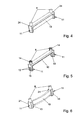
- FIG. 4 shows a variant of the molding 9 according to the invention with two coupling pins 8 and as an extension the coupling pin 8 in the direction of the folding surface 4 extend columns 11 and the columns 11 connecting slender web 10.
- the columns 11 have a greater width in the transverse direction than the coupling pin 8. This creates a paragraph 24 as a stop and support surface.
- the web 10 is designed very slim and connects to further stabilize the columns eleventh
- FIG. 5 shows a further variant of the molding 9 according to the invention with predetermined breaking points 12 and locking lugs 14th
- the pillars 11 extend beyond the web 10 and the parts of the pillars 11 protruding beyond the web 10 have predetermined breaking points 12 in the transverse direction to the seaming surface 4.
- the predetermined breaking points 12 are designed as one-sided notches.
- both columns 11 are traversed in the longitudinal direction of a slot 19.
- the longitudinal surfaces of the molding extending side surfaces 13, 21 of the columns 11 are designed resiliently. The degree of elasticity depends heavily on the material. Very good results were achieved with plastic materials. Also most conveniently made of a plastic is the coupling pin 8 with the receiving recesses 7 of the bottom surface 5 resilient, the bottom surface 5 engaging behind locking lugs 14th
- FIG. 6 shows a further variant of the molding 9 according to the invention with an arcuate web 10.
- the stable columns 11 are connected by the web 10.
- the web 10 is curved so far that it is at least flush in a partial area with a side surface 13 of the columns 11 to produce an additional holding force in the groove 18 in the assembled state.
Landscapes
- Engineering & Computer Science (AREA)
- Mechanical Engineering (AREA)
- Casings For Electric Apparatus (AREA)
- Packaging Frangible Articles (AREA)
Abstract
Description
- Die Erfindung betrifft eine Anordnung einer elektronischen Baueinheit an einem Rahmenprofil eines Fensters, einer Tür oder dergleichen, bestehend aus einem die elektronischen Bauteile aufnehmendes Gehäuse mit einer weitgehend ebenen, einer Falzfläche des Rahmenprofils zugewandten Bodenfläche und mit auf einer Längsachse zur Falzfläche befindlichen Aufnahmeausnehmungen in der Bodenfläche für Kupplungszapfen zumindest eines Formteils zur Anpassung der Bodenfläche an die Falzfläche des Rahmenprofils.
- Derartige Anordnungen sind vor allem für den Schutz von Öffnungen in Immobilien erforderlich. Sie dienen z.B. in Verbindung mit einem Gegenstück zur Detektion der Stellung eines Flügelrahmens. Da es allerding eine große Vielfalt bei der Ausgestaltung von Rahmenprofilen und damit auch der dazugehörigen Falzflächen gibt, ist eine Anpassung der elektronischen Baueinheit zur Befestigung an das jeweilige Rahmenprofil erforderlich.
- Eine elektronische Baueinheit an einem Rahmenprofil eines Fensters oder einer Tür ist aus dem Winkhaus-Produktkatalog -activPilot Control- (Seiten 11, 26 und 30) aus 12/2011 bekannt. Dort werden Formteile für die Anpassung der Bodenfläche des Gehäuses an die Falzfläche des Rahmenprofils verwendet. Für die unterschiedlichen Rahmenprofile werden verschiedene Formteile eingesetzt, die alle einheitliche Kupplungszapfen für die Aufnahmeausnehmungen in der Bodenfläche aufweisen und die Bodenfläche des Gehäuses weitgehend abdecken. Die weitere Kontur der verschiedenen Formteile ist den unterschiedlichen Rahmenprofilen angepasst. Mit zunehmender Vielfalt bei den Rahmenprofilen führt dies zu einer sehr großen Anzahl von unterschiedlichen Formteilen, die alle separat gelagert und verwaltet werden müssen. Die großflächige Kontur erschwert die bei elektronischen Baueinheiten teilweise erforderliche Kabelverlegung in diesem Bereich.
- Aus der
EP 1 801 328 A2 ist eine Anordnung einer elektronischen Baueinheit an einem Rahmenprofil eines Fensters oder dergleichen ersichtlich, bei der Formteile zur Profilanpassung verwendet werden. Es handelt sich hierbei um ein speziell an das Rahmenprofil angepasstes Formteil, welches sich zwischen der Bodenfläche des Gehäuses und der Falzfläche des Rahmenprofils befindet. Dies führt zu einer sehr großen Anzahl von unterschiedlichen Formteilen bei der Verwendung der elektronischen Baueinheit bei unterschiedlichen Rahmenprofilen. - Die
DE 203 19 387 U1 offenbart eine Schließblechanordnung mit einem U-förmigen Schließblech und mit einer in der Höhlung des U-Profils angeordneten Profilanpassung, die in Längsrichtung der Flügelfalzfläche erstreckende Stege und Nuten umgreift oder ausfüllt. Die Profilanpassung besteht unter anderem aus zumindest einem rechteckigen Profilstab, der über fluchtende Bohrungen mit dem Schließblech an der Falzfläche des Rahmenprofils verschraubt wird. Um eine Klemmung der Schließblechanordnung zu bewirken, sind erhabene Kerben an den Seiten des Profilstabes vorgesehen. Da die einzelnen Teile erst bei der Montage an der Falzfläche des Rahmenprofils miteinander verbunden werden, ist die Montage, insbesondere bei der Nachrüstung eines eingebauten Fensters, sehr schwierig und eine Vorfixierung der gesamten Schließblechanordnung ist nicht möglich. Um die für ein Schließblech erforderliche Festigkeit aufzuweisen, sind die Profilanpassung und der Profilstab aus zumindest annähernd quadratischem Vollmaterial ohne Konturverjüngungen in weniger tragenden Bereichen vorgesehen. Der Profilstab aus zumindest annähernd quadratischem Vollmaterial erstreckt sich zudem über die gesamte Schließblechlänge. Beides führt zu einem überhöhten Materialaufwand und erschwert die bei elektronischen Baueinheiten teilweise erforderliche Kabelverlegung in diesem Bereich. - Die Aufgabe besteht darin, eine einfache, universelle Befestigungsmöglichkeit für eine elektronische Baueinheit an unterschiedlichen Rahmenprofilen zu schaffen.
- Diese Aufgabe wird erfindungsgemäß mit den Merkmalen des Anspruchs 1 gelöst, wobei das Formteil aus Säulen gebildet wird, die sich als Verlängerung der Kupplungszapfen in Richtung zur Falzfläche erstrecken und einen verbindenden schlankeren Steg aufweisen.
Dadurch weist das Formteil nur in den Bereichen eine hohe Festigkeit auf, in denen hohe Kräfte ein- und wieder abgeleitet werden müssen, wenn das Formteil die elektronische Baueinheit auf einer unebenen Falzfläche des Rahmenprofils, mit Absätzen, Nuten und/oder Stegen, abstützt. Es ist besonders einfach und materialreduziert aufgebaut. Hinzu kommt, dass das Formteil durch die schlanke Form universell bei allen bekannten Rahmenprofilen zur Abstützung auf der Falzfläche eingesetzt werden kann. Das Formteil kann obendrein auch in schmale Nuten auf der Falzfläche eingesetzt werden und für die bei elektronischen Baueinheiten teilweise erforderliche Kabelverlegung ist in diesem Bereich noch ausreichend Platz vorhanden, ohne an dem Formteil Veränderungen vornehmen zu müssen. Die Säulen werden im Querschnitt bevorzugt rechteckig oder vieleckig ausgeführt, sie können aber auch z.B. rund oder oval sein. Es können auch mehrere Formteile der gleichen Art an der Bodenfläche des Gehäuses angeordnet werden. - Das Formteil lässt sich besonders einfach montieren, wenn die Säulen quer zur Falzfläche eine größere Breite aufweisen als die Kupplungszapfen. Die dadurch entstehenden Absätze zwischen Kupplungszapfen und Säule dienen als Anschlag des Formteils beim Eindrücken der Kupplungszapfen in die Aufnahmeausnehmungen der Bodenfläche des Gehäuses. Außerdem stützen die Absätze das Formteil gegen ein seitliches "Wegkippen" ab.
- Eine weitere Materialreduzierung lässt sich dadurch bewirken, dass sich das Formteil nur über einen Teilbereich der Bodenfläche in Längsrichtung zu der Falzfläche erstreckt. Dadurch wird das Formteil wesentlich verkürzt. Da das Formteil für eine elektronische Baueinheit nicht die Festigkeit des Formteils von einem Schließblech aufweisen muss, ist eine Abstützung über einen Teilbereich völlig ausreichend. Falls die elektronische Baueinheit zusätzlich im Rahmenprofil verschraubt wir, ist es empfehlenswert, dass eine Säule nahe an dem Schraubloch angeordnet ist.
- Nach einem weiteren Merkmal der Erfindung ist die Abstützung besonders stabil, wenn ein Schraubloch im Gehäuse senkrecht auf der Längsachse des Formteils zur Falzfläche angeordnet ist. Dadurch wird ein seitliches "Wegkippen" des Formteils mit der elektronischen Baueinheit durch die Vermeidung von Drehmomenten unterbunden. Das Anschrauben kann besonders einfach und sicher erfolgen.
- Ein weiterer Vorteil wird durch die Erfindung erzielt, wenn die sich längs des Formteils erstreckenden Seitenflächen der Säulen federelastisch ausgeführt sind. Dies kann z. B. durch die Verwendung von einem härteren Kunststoff im Kern der Säule und einem weicheren, federelastischen Kunststoff im Bereich der Seitenflächen erfolgen. Dadurch dient das Formteil nicht nur zur Abstützung auf der Falzfläche, sondern kann sich auch sehr schmalen Nuten anpassen und ist dadurch auch bei einer vorhandenen Nut auf der Falzfläche zur Vorfixierung der elektronischen Baueinheit auf der Falzfläche einsetzbar. Dieses Merkmal macht das Formteil wesentlich universeller. Da die Säulen nur relativ kleine Außenflächen aufweisen, ist ein Vorfixieren von Hand möglich. Dies ist insbesondere bei der Montage an einem bereits montierten Fenster besonders wichtig, um die Funktion der elektronischen Baueinheit zunächst einmal testen zu können, ohne diese zuvor an dem Rahmenprofil verschrauben zu müssen. Maßunterschiede und Toleranzen der Nuten werden ausgeglichen und ein Lösen gegen die Haltekraft ist möglich.
- Die Vorfixierung ist besonders einfach und sicher möglich, wenn die Säulen des Formteils senkrecht von der Bodenfläche weg, in Längsrichtung zu der Falzfläche einen Schlitz aufweisen. Das Formteil kann dadurch noch leichter in eine vorhandene Nut auf der Falzfläche eingedrückt werden, um eine sichere Vorfixierung der elektronischen Baueinheit zu erzielen. Je elastischer das verwendete Material der Säulen ausgeführt ist, umso einfacher kann das Formteil eingedrückt werden. Außerdem können noch größere Maßunterschiede und Toleranzen der Nuten ausgeglichen werden.
- Die Höhe des Formteils lässt sich gemäß einer vorteilhaften Weiterentwicklung der Erfindung einfach verändern, wenn die Säulen des Formteils über den Steg hinaus in Richtung der Falzfläche ragen und die über den Steg hinausragenden Teile Sollbruchstellen in Querrichtung zu der Falzfläche aufweisen. Die Sollbruchstellen lassen ein einfaches Kürzen der verstärkten Seitenränder zu. Damit ist das Formteil noch universeller einsetzbar, da es auch für unterschiedlich hohe Absätze, Nuten oder Stege der Falzfläche des Rahmenprofils einsetzbar ist. Die Anpassung kann z.B. durch einen Seitenschneider problemlos erfolgen. Die Sollbruchstelle sorgt auch für eine gerade Aufstandsfläche nach der Anpassung.
- Eine weitere erfindungsgemäße Ausgestaltung sieht vor, dass der Steg zwischen den Säulen soweit bogen- oder wellenförmig vorgeformt ist, dass er in einem oder mehreren Teilbereichen mit wenigstens einer Seitenfläche der Säulen zumindest bündig ist. Die Ausgestaltung bewirkt, dass nicht nur die Säulen die elektronische Baueinheit in der Nut vorfixieren, sondern auch der Steg in einem Teilbereich mit einer Seitenwandung der Nut anliegt und ebenfalls eine Haltekraft ausübt. Dies erhöht die Haltekräfte in der Nut der Falzfläche des Rahmenprofils.
- Gemäß einer weiteren erfindungsgemäßen Weiterentwicklung lässt sich das Formteil besonders einfach in eine Nut der Falzfläche des Rahmenprofils einsetzen, wenn die Seitenflächen der Säulen konisch verlaufen. Das Formteil lässt sich dadurch besonders einfach in die Öffnung der Nut ansetzen und mit ansteigendem Kraftaufwand in die Nut eindrücken.
- Eine besonders gute Verbindung zwischen der elektronischen Baueinheit und dem Rahmenprofil ist gegeben, wenn die Kupplungszapfen des Formteils für die Aufnahmeausnehmungen der Bodenfläche federelastische, die Bodenfläche hintergreifende Rastnasen aufweisen. Die Kupplungszapfen des Formteils sind dadurch nicht nur kraft- sondern auch formschlüssig mit der Bodenfläche des Gehäuses der elektronischen Baueinheit verbunden und verbinden somit das Formteil sicher mit der Bodenfläche des Gehäuses.
- Die Erfindung lässt zahlreiche Ausführungsformen zu. Zur weiteren Verdeutlichung ihres Grundprinzips sind mehrere davon in den Zeichnungen dargestellt und werden nachfolgend beschrieben. Diese zeigen perspektivisch in
- Fig.1
- eine elektronische Baueinheit an einem Rahmenprofil,
- Fig.2
- eine elektronische Baueinheit mit einem an der Bodenfläche angeordneten Formteil
- Fig.3
- eine elektronische Baueinheit mit einem korrespondierenden treibstangengesteuerten Kontaktgeber
- Fig.4
- eine Variante des erfindungsgemäßen Formteils
- Fig.5
- eine Variante des erfindungsgemäßen Formteils mit Sollbruchstellen und Rasthaken
- Fig.6
- eine Variante des erfindungsgemäßen Formteils mit bogenförmigem Steg
-
Figur 1 zeigt eine elektronische Baueinheit 2 an einem nur beispielhaften Rahmenprofil 1. Die elektronischen Bauteile 20 aufweisende elektronische Baueinheit 2 ist mit ihrem Gehäuse 3 an der Falzfläche 4 des Rahmenprofils 1 angeordnet. Es ist gut ersichtlich, dass die Falzfläche 4 übliche Stege und eine Nut 18 aufweist. Die sehr unterschiedlichen Ausführungsformen der Falzfläche 4 unterschiedlichster Profilhersteller, mit Absätzen, Stegen und Nuten in einer Vielzahl von Varianten machen es besonders schwierig, geeignete Formteile zu entwickeln. -
Figur 2 zeigt die elektronische Baueinheit 2 ausFigur 1 mit einem Formteil 9 an der Bodenfläche 5 des Gehäuses 3. In der Bodenfläche befinden sich auf jeder Längsachse 6, 22 jeweils zwei Aufnahmeausnehmungen 7 und ein Schraubloch 15. Das Formteil 9 erstreckt sich nur über einen Teilbereich der Bodenfläche 5 und nur auf einer Seite des Schraubloches 15 auf der Längsachse 6. Eine Säule 11 des Formteils 9 ist nahe an dem Schraubloch 15 derselben Längsachse 6 angeordnet. Ein weiteres Formteil 9 könnte bei Bedarf auf der parallelen Längsachse 22 in die Aufnahmeausnehmungen 7 eingesetzt werden. - In
Figur 3 ist die elektronische Baueinheit 2 in Kombination mit einem korrespondierenden, über eine Treibstange 17 gesteuerten Kontaktgeber 16 ersichtlich. Die elektronische Baueinheit 2 weist ein umschließendes Gehäuse 3 und ein an der Bodenfläche 5 des Gehäuses 3 angeordnetes Formteil 9 auf. Die elektronische Baueinheit 2 wird mit dem Formteil 9 auf einem ausFigur 1 bekannten Rahmenprofil 1 angeordnet, wobei der über eine Treibstange 17 gesteuerte Kontaktgeber 16 auf einem gegenüberliegenden, nicht dargestellten Rahmenprofil angeordnet ist. Der Kontaktgeber 16 ist für eine genaue Anpassung an die elektronische Baueinheit 2 exzentrisch ausgeführt. Um eine Einstellung des Kontaktgebers 16 bei der Montage zu erleichtern, ist dieser an der Unterseite mit einem Magnet und einer die Kontur eines Stiftkopfes 23 aufweisende Ausnehmung versehen, um den Kontaktgeber 16 auf dem mit der Treibstange 17 gekoppelten Stiftkopf 23 lösbar vorfixieren zu können. Wenn die Montageeinstellungen abgeschlossen sind, kann der Kontaktgeber 16 dauerhaft, z.B. durch ein Klebemittel, mit dem Stiftkopf 23 verbunden werden. -
Figur 4 zeigt eine Variante des erfindungsgemäßen Formteils 9 mit zwei Kupplungszapfen 8 und sich als Verlängerung der Kupplungszapfen 8 in Richtung zur Falzfläche 4 erstrecken Säulen 11 und einen die Säulen 11 verbindenden schlankeren Steg 10. Die Säulen 11 weisen in Querrichtung eine größere Breite auf als die Kupplungszapfen 8. Dadurch entsteht ein Absatz 24 als Anschlag- und Auflagefläche. Der Steg 10 ist sehr schlank ausgeführt und verbindet zur weiteren Stabilisierung die Säulen 11. -
Figur 5 zeigt eine weitere Variante des erfindungsgemäßen Formteils 9 mit Sollbruchstellen 12 und Rastnasen 14.
Die Säulen 11 erstrecken sind über den Steg 10 hinaus und die über den Steg 10 hinausragenden Teile der Säulen 11 weisen Sollbruchstellen 12 in Querrichtung zu der Falzfläche 4 auf. Die Sollbruchstellen 12 sind als einseitige Einkerbungen ausgeführt. Außerdem sind beiden Säulen 11 in Längsrichtung von einen Schlitz 19 durchzogen. Dadurch sind die sich längs des Formteils erstreckenden Seitenflächen 13, 21 der Säulen 11 federelastisch ausgeführt. Der Grad der federelastischen Wirkung hängt stark vom Material ab. Sehr gute Ergebnisse wurden mit Kunststoffmaterialien erzielt. Ebenfalls am günstigsten aus einem Kunststoff hergestellt ist der Kupplungszapfen 8 mit für die Aufnahmeausnehmungen 7 der Bodenfläche 5 federelastischen, die Bodenfläche 5 hintergreifenden Rastnasen 14. - Die
Figur 6 zeigt eine weitere Variante des erfindungsgemäßen Formteils 9 mit einem bogenförmigen Steg 10. Die stabilen Säulen 11 sind durch den Steg 10 verbunden. Der Steg 10 ist so weit bogenförmig geformt, dass er in einem Teilbereich mit einer Seitenfläche 13 der Säulen 11 zumindest bündig ist, um im montierten Zustand eine zusätzliche Haltekraft in der Nut 18 zu erzeugen.
Claims (10)
- Anordnung einer elektronischen Baueinheit (2) an einem Rahmenprofil (1) eines Fensters, einer Tür oder dergleichen, bestehend aus einem die elektronischen Bauteile (20) aufnehmenden Gehäuse (3) mit einer weitgehend ebenen, einer Falzfläche (4) des Rahmenprofils (1) zugewandten Bodenfläche (5) und mit auf einer Längsachse (6) zur Falzfläche (4) befindlichen Aufnahmeausnehmungen (7) in der Bodenfläche (5) für Kupplungszapfen (8) zumindest eines Formteils (9) zur Anpassung der Bodenfläche (5) an die Falzfläche (4) des Rahmenprofils (1), dadurch gekennzeichnet, dass das Formteil (9) aus Säulen (11) gebildet wird, die sich als Verlängerung der Kupplungszapfen (8) in Richtung zur Falzfläche (4) erstrecken und einen verbindenden schlankeren Steg (10) aufweisen.
- Anordnung einer elektronischen Baueinheit nach Anspruch 1, dadurch gekennzeichnet, dass die Säulen (11) quer zur Falzfläche (4) eine größere Breite aufweisen als die Kupplungszapfen (8).
- Anordnung einer elektronischen Baueinheit nach einem der vorherigen Ansprüche, dadurch gekennzeichnet, dass sich das Formteil (9) nur über einen Teilbereich der Bodenfläche (5) in Längsrichtung zu der Falzfläche (4) erstreckt.
- Anordnung einer elektronischen Baueinheit nach einem der vorherigen Ansprüche, dadurch gekennzeichnet, dass ein Schraubloch (15) im Gehäuse senkrecht auf der Längsachse (6) des Formteils (9) zur Falzfläche (4) angeordnet ist.
- Anordnung einer elektronischen Baueinheit nach einem der vorherigen Ansprüche, dadurch gekennzeichnet, dass die sich längs des Formteils erstreckenden Seitenflächen (13) der Säulen (11) federelastisch ausgeführt sind.
- Anordnung einer elektronischen Baueinheit nach Anspruch 5, dadurch gekennzeichnet, dass die Säulen (11) des Formteils (9) senkrecht von der Bodenfläche (5) weg, in Längsrichtung zu der Falzfläche (4) einen Schlitz (19) aufweisen.
- Anordnung einer elektronischen Baueinheit nach einem der vorherigen Ansprüche, dadurch gekennzeichnet, dass die Säulen (11) des Formteils (9)über den Steg (10) hinaus in Richtung der Falzfläche (4) ragen und die über den Steg (10) hinausragenden Teile Sollbruchstellen (12) in Querrichtung zu der Falzfläche (4) aufweisen.
- Anordnung einer elektronischen Baueinheit nach einem der vorherigen Ansprüche, dadurch gekennzeichnet, dass der Steg (10) zwischen den Säulen (11) soweit bogen- oder wellenförmig vorgeformt ist, dass er in einem oder mehreren Teilbereichen mit wenigstens einer Seitenfläche (13, 21) der Säulen (11) zumindest bündig ist.
- Anordnung einer elektronischen Baueinheit nach einem der vorherigen Ansprüche, dadurch gekennzeichnet, dass die Außenflächen (13, 21) der Säulen (11) konisch verlaufen.
- Anordnung einer elektronischen Baueinheit nach einem der vorherigen Ansprüche, dadurch gekennzeichnet, dass die Kupplungszapfen (8) des Formteils (9) für die Aufnahmeausnehmungen (7) der Bodenfläche (5) federelastische, die Bodenfläche (5) hintergreifende Rastnasen (14) aufweisen.
Applications Claiming Priority (1)
| Application Number | Priority Date | Filing Date | Title |
|---|---|---|---|
| DE102014203820.0A DE102014203820A1 (de) | 2014-03-03 | 2014-03-03 | Anordnung einer elektronischen Baueinheit an ein Rahmenprofil |
Publications (3)
| Publication Number | Publication Date |
|---|---|
| EP2915938A2 true EP2915938A2 (de) | 2015-09-09 |
| EP2915938A3 EP2915938A3 (de) | 2015-09-16 |
| EP2915938B1 EP2915938B1 (de) | 2017-03-15 |
Family
ID=52423588
Family Applications (1)
| Application Number | Title | Priority Date | Filing Date |
|---|---|---|---|
| EP15152065.7A Active EP2915938B1 (de) | 2014-03-03 | 2015-01-22 | Elektronische Baueinheit zur Anordnung an einem Rahmenprofil |
Country Status (2)
| Country | Link |
|---|---|
| EP (1) | EP2915938B1 (de) |
| DE (1) | DE102014203820A1 (de) |
Families Citing this family (3)
| Publication number | Priority date | Publication date | Assignee | Title |
|---|---|---|---|---|
| DE102017130812A1 (de) * | 2017-12-20 | 2019-06-27 | Veka Ag | Schaltkontakteinheit zur Montage an einem Falz zwischen einem Blendrahmen und einem Fenster- oder Türflügel |
| DE102018204100A1 (de) * | 2018-03-16 | 2019-09-19 | Roto Frank Ag | Beschlaganordnung für einen Flügelrahmen eines Fensters, entsprechendes Fenster, Verfahren zum Betreiben einer Beschlaganordnung, Verfahren zum Montieren einer Beschlaganordnung sowie Sensoreinrichtung |
| DE202021100807U1 (de) * | 2021-02-18 | 2021-04-08 | Thomas Buchhalter | Fensteralarmsystem |
Citations (2)
| Publication number | Priority date | Publication date | Assignee | Title |
|---|---|---|---|---|
| DE20319387U1 (de) | 2003-12-12 | 2004-02-26 | Siegenia-Aubi Kg | Schließblechanordnung |
| EP1801328A2 (de) | 2005-12-13 | 2007-06-27 | Aug. Winkhaus GmbH & Co. KG | Überwachbare Verriegelungsanordnung für ein Fenster, eine Türe oder dergleichen und Verfahren zum Betrieb einer solchen Verriegelungsanordnung |
Family Cites Families (2)
| Publication number | Priority date | Publication date | Assignee | Title |
|---|---|---|---|---|
| DE9100436U1 (de) * | 1991-01-15 | 1991-04-04 | Roto Frank AG, 7022 Leinfelden-Echterdingen | Befestigung eines Getriebes an einem Flügel eines Fensters, einer Tür o.dgl. |
| DE10155478A1 (de) * | 2001-11-12 | 2003-05-22 | Unilux Ag | Fenster- oder Türrahmen und damit verwendbare Komponenten |
-
2014
- 2014-03-03 DE DE102014203820.0A patent/DE102014203820A1/de not_active Withdrawn
-
2015
- 2015-01-22 EP EP15152065.7A patent/EP2915938B1/de active Active
Patent Citations (2)
| Publication number | Priority date | Publication date | Assignee | Title |
|---|---|---|---|---|
| DE20319387U1 (de) | 2003-12-12 | 2004-02-26 | Siegenia-Aubi Kg | Schließblechanordnung |
| EP1801328A2 (de) | 2005-12-13 | 2007-06-27 | Aug. Winkhaus GmbH & Co. KG | Überwachbare Verriegelungsanordnung für ein Fenster, eine Türe oder dergleichen und Verfahren zum Betrieb einer solchen Verriegelungsanordnung |
Also Published As
| Publication number | Publication date |
|---|---|
| EP2915938B1 (de) | 2017-03-15 |
| EP2915938A3 (de) | 2015-09-16 |
| DE102014203820A1 (de) | 2015-09-03 |
Similar Documents
| Publication | Publication Date | Title |
|---|---|---|
| EP2750550B1 (de) | Schublade | |
| DE102009043993B4 (de) | Hilfsvorrichtung zur Befestigung eines Distanzelementes an einem Bodenbrett | |
| EP2730195B1 (de) | Vorrichtung zur Verbindung der Front eines bewegbaren Möbelteils mit dessen Seitenteil | |
| EP2681817B1 (de) | Sockel oder anbaurahmen für einen schaltschrank oder ein rack | |
| EP3257121B1 (de) | Anordnung mehrerer rastfüsse für eine baugruppe | |
| WO2007093207A1 (de) | Verspannbare befestigungseinrichtung | |
| EP2915938B1 (de) | Elektronische Baueinheit zur Anordnung an einem Rahmenprofil | |
| EP0670945B1 (de) | Stütze mit abnehmbarem stützenkopf | |
| DE202009013488U1 (de) | Vorrichtung zum Fixieren eines Baukörpers in einer Gebäudeöffnung | |
| EP3082511B1 (de) | Schubladenfrontanbindungseinheit | |
| EP3430945B1 (de) | Vorrichtung zur verbindung einer front mit einer zarge | |
| EP2790958B1 (de) | Sitztiefenverstellung, insbesondere für einen fahrzeugsitz | |
| EP2407604A1 (de) | Verbindungsvorrichtung | |
| EP3348746B1 (de) | Fassadenplattenanordnung | |
| EP2880226B1 (de) | KIPPBARE FUßBODENPROFILANORDNUNG | |
| DE202016101225U1 (de) | Unterbauelement mit Wabenstruktur und Höhenjustierungsmitteln | |
| EP3025938B1 (de) | Abdeckvorrichtung für eine flächenseite eines wandelements | |
| AT413583B (de) | Stabilisierungsvorrichtung für möbelteile | |
| DE202012102863U1 (de) | Befestigungseinrichtung für ein Flächenelement an einem C-Profil | |
| DE102014109970B4 (de) | Gehäuse | |
| DE19828233A1 (de) | Wandkonsole | |
| DE102013214597B3 (de) | Duschkorb | |
| DE19831782C2 (de) | Sollbruchelement | |
| CH653793A5 (de) | Halter fuer nummerntafel. | |
| DE102005007451B4 (de) | Feststeller für Rückwände an Kastenmöbeln |
Legal Events
| Date | Code | Title | Description |
|---|---|---|---|
| PUAL | Search report despatched |
Free format text: ORIGINAL CODE: 0009013 |
|
| PUAI | Public reference made under article 153(3) epc to a published international application that has entered the european phase |
Free format text: ORIGINAL CODE: 0009012 |
|
| AK | Designated contracting states |
Kind code of ref document: A2 Designated state(s): AL AT BE BG CH CY CZ DE DK EE ES FI FR GB GR HR HU IE IS IT LI LT LU LV MC MK MT NL NO PL PT RO RS SE SI SK SM TR |
|
| AX | Request for extension of the european patent |
Extension state: BA ME |
|
| AK | Designated contracting states |
Kind code of ref document: A3 Designated state(s): AL AT BE BG CH CY CZ DE DK EE ES FI FR GB GR HR HU IE IS IT LI LT LU LV MC MK MT NL NO PL PT RO RS SE SI SK SM TR |
|
| AX | Request for extension of the european patent |
Extension state: BA ME |
|
| RIC1 | Information provided on ipc code assigned before grant |
Ipc: E05B 9/08 20060101ALI20150811BHEP Ipc: E05B 17/22 20060101AFI20150811BHEP Ipc: E05B 47/00 20060101ALN20150811BHEP Ipc: E05C 9/18 20060101ALI20150811BHEP Ipc: G08B 13/08 20060101ALI20150811BHEP |
|
| 17P | Request for examination filed |
Effective date: 20160128 |
|
| RBV | Designated contracting states (corrected) |
Designated state(s): AL AT BE BG CH CY CZ DE DK EE ES FI FR GB GR HR HU IE IS IT LI LT LU LV MC MK MT NL NO PL PT RO RS SE SI SK SM TR |
|
| GRAP | Despatch of communication of intention to grant a patent |
Free format text: ORIGINAL CODE: EPIDOSNIGR1 |
|
| RIC1 | Information provided on ipc code assigned before grant |
Ipc: G08B 13/08 20060101ALI20160928BHEP Ipc: E05B 17/22 20060101AFI20160928BHEP Ipc: E05C 9/18 20060101ALI20160928BHEP Ipc: E05B 9/08 20060101ALI20160928BHEP Ipc: E05B 47/00 20060101ALN20160928BHEP |
|
| RIC1 | Information provided on ipc code assigned before grant |
Ipc: E05C 9/18 20060101ALI20161013BHEP Ipc: G08B 13/08 20060101ALI20161013BHEP Ipc: E05B 47/00 20060101ALN20161013BHEP Ipc: E05B 9/08 20060101ALI20161013BHEP Ipc: E05B 17/22 20060101AFI20161013BHEP |
|
| INTG | Intention to grant announced |
Effective date: 20161026 |
|
| GRAS | Grant fee paid |
Free format text: ORIGINAL CODE: EPIDOSNIGR3 |
|
| GRAA | (expected) grant |
Free format text: ORIGINAL CODE: 0009210 |
|
| AK | Designated contracting states |
Kind code of ref document: B1 Designated state(s): AL AT BE BG CH CY CZ DE DK EE ES FI FR GB GR HR HU IE IS IT LI LT LU LV MC MK MT NL NO PL PT RO RS SE SI SK SM TR |
|
| REG | Reference to a national code |
Ref country code: CH Ref legal event code: EP Ref country code: GB Ref legal event code: FG4D Free format text: NOT ENGLISH |
|
| REG | Reference to a national code |
Ref country code: IE Ref legal event code: FG4D Free format text: LANGUAGE OF EP DOCUMENT: GERMAN |
|
| REG | Reference to a national code |
Ref country code: AT Ref legal event code: REF Ref document number: 875754 Country of ref document: AT Kind code of ref document: T Effective date: 20170415 |
|
| REG | Reference to a national code |
Ref country code: DE Ref legal event code: R096 Ref document number: 502015000702 Country of ref document: DE |
|
| REG | Reference to a national code |
Ref country code: NL Ref legal event code: MP Effective date: 20170315 |
|
| REG | Reference to a national code |
Ref country code: LT Ref legal event code: MG4D |
|
| PG25 | Lapsed in a contracting state [announced via postgrant information from national office to epo] |
Ref country code: GR Free format text: LAPSE BECAUSE OF FAILURE TO SUBMIT A TRANSLATION OF THE DESCRIPTION OR TO PAY THE FEE WITHIN THE PRESCRIBED TIME-LIMIT Effective date: 20170616 Ref country code: HR Free format text: LAPSE BECAUSE OF FAILURE TO SUBMIT A TRANSLATION OF THE DESCRIPTION OR TO PAY THE FEE WITHIN THE PRESCRIBED TIME-LIMIT Effective date: 20170315 Ref country code: NO Free format text: LAPSE BECAUSE OF FAILURE TO SUBMIT A TRANSLATION OF THE DESCRIPTION OR TO PAY THE FEE WITHIN THE PRESCRIBED TIME-LIMIT Effective date: 20170615 Ref country code: LT Free format text: LAPSE BECAUSE OF FAILURE TO SUBMIT A TRANSLATION OF THE DESCRIPTION OR TO PAY THE FEE WITHIN THE PRESCRIBED TIME-LIMIT Effective date: 20170315 Ref country code: FI Free format text: LAPSE BECAUSE OF FAILURE TO SUBMIT A TRANSLATION OF THE DESCRIPTION OR TO PAY THE FEE WITHIN THE PRESCRIBED TIME-LIMIT Effective date: 20170315 |
|
| PG25 | Lapsed in a contracting state [announced via postgrant information from national office to epo] |
Ref country code: SE Free format text: LAPSE BECAUSE OF FAILURE TO SUBMIT A TRANSLATION OF THE DESCRIPTION OR TO PAY THE FEE WITHIN THE PRESCRIBED TIME-LIMIT Effective date: 20170315 Ref country code: LV Free format text: LAPSE BECAUSE OF FAILURE TO SUBMIT A TRANSLATION OF THE DESCRIPTION OR TO PAY THE FEE WITHIN THE PRESCRIBED TIME-LIMIT Effective date: 20170315 Ref country code: RS Free format text: LAPSE BECAUSE OF FAILURE TO SUBMIT A TRANSLATION OF THE DESCRIPTION OR TO PAY THE FEE WITHIN THE PRESCRIBED TIME-LIMIT Effective date: 20170315 Ref country code: BG Free format text: LAPSE BECAUSE OF FAILURE TO SUBMIT A TRANSLATION OF THE DESCRIPTION OR TO PAY THE FEE WITHIN THE PRESCRIBED TIME-LIMIT Effective date: 20170615 |
|
| PG25 | Lapsed in a contracting state [announced via postgrant information from national office to epo] |
Ref country code: NL Free format text: LAPSE BECAUSE OF FAILURE TO SUBMIT A TRANSLATION OF THE DESCRIPTION OR TO PAY THE FEE WITHIN THE PRESCRIBED TIME-LIMIT Effective date: 20170315 |
|
| PG25 | Lapsed in a contracting state [announced via postgrant information from national office to epo] |
Ref country code: RO Free format text: LAPSE BECAUSE OF FAILURE TO SUBMIT A TRANSLATION OF THE DESCRIPTION OR TO PAY THE FEE WITHIN THE PRESCRIBED TIME-LIMIT Effective date: 20170315 Ref country code: CZ Free format text: LAPSE BECAUSE OF FAILURE TO SUBMIT A TRANSLATION OF THE DESCRIPTION OR TO PAY THE FEE WITHIN THE PRESCRIBED TIME-LIMIT Effective date: 20170315 Ref country code: SK Free format text: LAPSE BECAUSE OF FAILURE TO SUBMIT A TRANSLATION OF THE DESCRIPTION OR TO PAY THE FEE WITHIN THE PRESCRIBED TIME-LIMIT Effective date: 20170315 Ref country code: ES Free format text: LAPSE BECAUSE OF FAILURE TO SUBMIT A TRANSLATION OF THE DESCRIPTION OR TO PAY THE FEE WITHIN THE PRESCRIBED TIME-LIMIT Effective date: 20170315 Ref country code: EE Free format text: LAPSE BECAUSE OF FAILURE TO SUBMIT A TRANSLATION OF THE DESCRIPTION OR TO PAY THE FEE WITHIN THE PRESCRIBED TIME-LIMIT Effective date: 20170315 |
|
| PG25 | Lapsed in a contracting state [announced via postgrant information from national office to epo] |
Ref country code: PT Free format text: LAPSE BECAUSE OF FAILURE TO SUBMIT A TRANSLATION OF THE DESCRIPTION OR TO PAY THE FEE WITHIN THE PRESCRIBED TIME-LIMIT Effective date: 20170717 Ref country code: SM Free format text: LAPSE BECAUSE OF FAILURE TO SUBMIT A TRANSLATION OF THE DESCRIPTION OR TO PAY THE FEE WITHIN THE PRESCRIBED TIME-LIMIT Effective date: 20170315 Ref country code: IS Free format text: LAPSE BECAUSE OF FAILURE TO SUBMIT A TRANSLATION OF THE DESCRIPTION OR TO PAY THE FEE WITHIN THE PRESCRIBED TIME-LIMIT Effective date: 20170715 Ref country code: PL Free format text: LAPSE BECAUSE OF FAILURE TO SUBMIT A TRANSLATION OF THE DESCRIPTION OR TO PAY THE FEE WITHIN THE PRESCRIBED TIME-LIMIT Effective date: 20170315 |
|
| REG | Reference to a national code |
Ref country code: DE Ref legal event code: R097 Ref document number: 502015000702 Country of ref document: DE |
|
| PLBE | No opposition filed within time limit |
Free format text: ORIGINAL CODE: 0009261 |
|
| STAA | Information on the status of an ep patent application or granted ep patent |
Free format text: STATUS: NO OPPOSITION FILED WITHIN TIME LIMIT |
|
| REG | Reference to a national code |
Ref country code: FR Ref legal event code: PLFP Year of fee payment: 4 |
|
| PG25 | Lapsed in a contracting state [announced via postgrant information from national office to epo] |
Ref country code: DK Free format text: LAPSE BECAUSE OF FAILURE TO SUBMIT A TRANSLATION OF THE DESCRIPTION OR TO PAY THE FEE WITHIN THE PRESCRIBED TIME-LIMIT Effective date: 20170315 |
|
| 26N | No opposition filed |
Effective date: 20171218 |
|
| PG25 | Lapsed in a contracting state [announced via postgrant information from national office to epo] |
Ref country code: SI Free format text: LAPSE BECAUSE OF FAILURE TO SUBMIT A TRANSLATION OF THE DESCRIPTION OR TO PAY THE FEE WITHIN THE PRESCRIBED TIME-LIMIT Effective date: 20170315 Ref country code: IT Free format text: LAPSE BECAUSE OF FAILURE TO SUBMIT A TRANSLATION OF THE DESCRIPTION OR TO PAY THE FEE WITHIN THE PRESCRIBED TIME-LIMIT Effective date: 20170315 |
|
| REG | Reference to a national code |
Ref country code: CH Ref legal event code: PL |
|
| PG25 | Lapsed in a contracting state [announced via postgrant information from national office to epo] |
Ref country code: MT Free format text: LAPSE BECAUSE OF FAILURE TO SUBMIT A TRANSLATION OF THE DESCRIPTION OR TO PAY THE FEE WITHIN THE PRESCRIBED TIME-LIMIT Effective date: 20170315 |
|
| PG25 | Lapsed in a contracting state [announced via postgrant information from national office to epo] |
Ref country code: LU Free format text: LAPSE BECAUSE OF NON-PAYMENT OF DUE FEES Effective date: 20180122 |
|
| REG | Reference to a national code |
Ref country code: IE Ref legal event code: MM4A |
|
| REG | Reference to a national code |
Ref country code: BE Ref legal event code: MM Effective date: 20180131 |
|
| PG25 | Lapsed in a contracting state [announced via postgrant information from national office to epo] |
Ref country code: CH Free format text: LAPSE BECAUSE OF NON-PAYMENT OF DUE FEES Effective date: 20180131 Ref country code: LI Free format text: LAPSE BECAUSE OF NON-PAYMENT OF DUE FEES Effective date: 20180131 Ref country code: BE Free format text: LAPSE BECAUSE OF NON-PAYMENT OF DUE FEES Effective date: 20180131 |
|
| PG25 | Lapsed in a contracting state [announced via postgrant information from national office to epo] |
Ref country code: IE Free format text: LAPSE BECAUSE OF NON-PAYMENT OF DUE FEES Effective date: 20180122 |
|
| PG25 | Lapsed in a contracting state [announced via postgrant information from national office to epo] |
Ref country code: MC Free format text: LAPSE BECAUSE OF FAILURE TO SUBMIT A TRANSLATION OF THE DESCRIPTION OR TO PAY THE FEE WITHIN THE PRESCRIBED TIME-LIMIT Effective date: 20170315 |
|
| GBPC | Gb: european patent ceased through non-payment of renewal fee |
Effective date: 20190122 |
|
| PG25 | Lapsed in a contracting state [announced via postgrant information from national office to epo] |
Ref country code: GB Free format text: LAPSE BECAUSE OF NON-PAYMENT OF DUE FEES Effective date: 20190122 |
|
| PG25 | Lapsed in a contracting state [announced via postgrant information from national office to epo] |
Ref country code: TR Free format text: LAPSE BECAUSE OF FAILURE TO SUBMIT A TRANSLATION OF THE DESCRIPTION OR TO PAY THE FEE WITHIN THE PRESCRIBED TIME-LIMIT Effective date: 20170315 |
|
| PG25 | Lapsed in a contracting state [announced via postgrant information from national office to epo] |
Ref country code: HU Free format text: LAPSE BECAUSE OF FAILURE TO SUBMIT A TRANSLATION OF THE DESCRIPTION OR TO PAY THE FEE WITHIN THE PRESCRIBED TIME-LIMIT; INVALID AB INITIO Effective date: 20150122 Ref country code: CY Free format text: LAPSE BECAUSE OF FAILURE TO SUBMIT A TRANSLATION OF THE DESCRIPTION OR TO PAY THE FEE WITHIN THE PRESCRIBED TIME-LIMIT Effective date: 20170315 Ref country code: MK Free format text: LAPSE BECAUSE OF NON-PAYMENT OF DUE FEES Effective date: 20170315 |
|
| PG25 | Lapsed in a contracting state [announced via postgrant information from national office to epo] |
Ref country code: AL Free format text: LAPSE BECAUSE OF FAILURE TO SUBMIT A TRANSLATION OF THE DESCRIPTION OR TO PAY THE FEE WITHIN THE PRESCRIBED TIME-LIMIT Effective date: 20170315 |
|
| PGFP | Annual fee paid to national office [announced via postgrant information from national office to epo] |
Ref country code: FR Payment date: 20230123 Year of fee payment: 9 |
|
| P01 | Opt-out of the competence of the unified patent court (upc) registered |
Effective date: 20230515 |
|
| PG25 | Lapsed in a contracting state [announced via postgrant information from national office to epo] |
Ref country code: FR Free format text: LAPSE BECAUSE OF NON-PAYMENT OF DUE FEES Effective date: 20240131 |
|
| PG25 | Lapsed in a contracting state [announced via postgrant information from national office to epo] |
Ref country code: FR Free format text: LAPSE BECAUSE OF NON-PAYMENT OF DUE FEES Effective date: 20240131 |
|
| REG | Reference to a national code |
Ref country code: DE Ref legal event code: R081 Ref document number: 502015000702 Country of ref document: DE Owner name: AUG. WINKHAUS SE & CO. KG, DE Free format text: FORMER OWNER: AUG. WINKHAUS GMBH & CO. KG, 48291 TELGTE, DE Ref country code: DE Ref legal event code: R081 Ref document number: 502015000702 Country of ref document: DE Owner name: AUG. WINKHAUS SE, DE Free format text: FORMER OWNER: AUG. WINKHAUS GMBH & CO. KG, 48291 TELGTE, DE |
|
| REG | Reference to a national code |
Ref country code: DE Ref legal event code: R081 Ref document number: 502015000702 Country of ref document: DE Owner name: AUG. WINKHAUS SE, DE Free format text: FORMER OWNER: AUG. WINKHAUS SE & CO. KG, 48291 TELGTE, DE |
|
| PGFP | Annual fee paid to national office [announced via postgrant information from national office to epo] |
Ref country code: DE Payment date: 20260120 Year of fee payment: 12 |
|
| PGFP | Annual fee paid to national office [announced via postgrant information from national office to epo] |
Ref country code: AT Payment date: 20260119 Year of fee payment: 12 |