EP2916006B1 - Pompe électrique - Google Patents
Pompe électrique Download PDFInfo
- Publication number
- EP2916006B1 EP2916006B1 EP15155864.0A EP15155864A EP2916006B1 EP 2916006 B1 EP2916006 B1 EP 2916006B1 EP 15155864 A EP15155864 A EP 15155864A EP 2916006 B1 EP2916006 B1 EP 2916006B1
- Authority
- EP
- European Patent Office
- Prior art keywords
- pump
- inlet port
- unit
- diameter
- rotor
- Prior art date
- Legal status (The legal status is an assumption and is not a legal conclusion. Google has not performed a legal analysis and makes no representation as to the accuracy of the status listed.)
- Active
Links
Images



Classifications
-
- F—MECHANICAL ENGINEERING; LIGHTING; HEATING; WEAPONS; BLASTING
- F04—POSITIVE - DISPLACEMENT MACHINES FOR LIQUIDS; PUMPS FOR LIQUIDS OR ELASTIC FLUIDS
- F04C—ROTARY-PISTON, OR OSCILLATING-PISTON, POSITIVE-DISPLACEMENT MACHINES FOR LIQUIDS; ROTARY-PISTON, OR OSCILLATING-PISTON, POSITIVE-DISPLACEMENT PUMPS
- F04C2/00—Rotary-piston machines or pumps
- F04C2/08—Rotary-piston machines or pumps of intermeshing-engagement type, i.e. with engagement of co-operating members similar to that of toothed gearing
- F04C2/10—Rotary-piston machines or pumps of intermeshing-engagement type, i.e. with engagement of co-operating members similar to that of toothed gearing of internal-axis type with the outer member having more teeth or tooth-equivalents, e.g. rollers, than the inner member
-
- F—MECHANICAL ENGINEERING; LIGHTING; HEATING; WEAPONS; BLASTING
- F01—MACHINES OR ENGINES IN GENERAL; ENGINE PLANTS IN GENERAL; STEAM ENGINES
- F01C—ROTARY-PISTON OR OSCILLATING-PISTON MACHINES OR ENGINES
- F01C21/00—Component parts, details or accessories not provided for in groups F01C1/00 - F01C20/00
- F01C21/10—Outer members for co-operation with rotary pistons; Casings
-
- F—MECHANICAL ENGINEERING; LIGHTING; HEATING; WEAPONS; BLASTING
- F04—POSITIVE - DISPLACEMENT MACHINES FOR LIQUIDS; PUMPS FOR LIQUIDS OR ELASTIC FLUIDS
- F04C—ROTARY-PISTON, OR OSCILLATING-PISTON, POSITIVE-DISPLACEMENT MACHINES FOR LIQUIDS; ROTARY-PISTON, OR OSCILLATING-PISTON, POSITIVE-DISPLACEMENT PUMPS
- F04C15/00—Component parts, details or accessories of machines, pumps or pumping installations, not provided for in groups F04C2/00 - F04C14/00
- F04C15/0057—Driving elements, brakes, couplings, transmission specially adapted for machines or pumps
- F04C15/008—Prime movers
-
- F—MECHANICAL ENGINEERING; LIGHTING; HEATING; WEAPONS; BLASTING
- F04—POSITIVE - DISPLACEMENT MACHINES FOR LIQUIDS; PUMPS FOR LIQUIDS OR ELASTIC FLUIDS
- F04C—ROTARY-PISTON, OR OSCILLATING-PISTON, POSITIVE-DISPLACEMENT MACHINES FOR LIQUIDS; ROTARY-PISTON, OR OSCILLATING-PISTON, POSITIVE-DISPLACEMENT PUMPS
- F04C15/00—Component parts, details or accessories of machines, pumps or pumping installations, not provided for in groups F04C2/00 - F04C14/00
- F04C15/06—Arrangements for admission or discharge of the working fluid, e.g. constructional features of the inlet or outlet
-
- F—MECHANICAL ENGINEERING; LIGHTING; HEATING; WEAPONS; BLASTING
- F04—POSITIVE - DISPLACEMENT MACHINES FOR LIQUIDS; PUMPS FOR LIQUIDS OR ELASTIC FLUIDS
- F04C—ROTARY-PISTON, OR OSCILLATING-PISTON, POSITIVE-DISPLACEMENT MACHINES FOR LIQUIDS; ROTARY-PISTON, OR OSCILLATING-PISTON, POSITIVE-DISPLACEMENT PUMPS
- F04C2/00—Rotary-piston machines or pumps
- F04C2/08—Rotary-piston machines or pumps of intermeshing-engagement type, i.e. with engagement of co-operating members similar to that of toothed gearing
- F04C2/082—Details specially related to intermeshing engagement type machines or pumps
- F04C2/084—Toothed wheels
-
- F—MECHANICAL ENGINEERING; LIGHTING; HEATING; WEAPONS; BLASTING
- F04—POSITIVE - DISPLACEMENT MACHINES FOR LIQUIDS; PUMPS FOR LIQUIDS OR ELASTIC FLUIDS
- F04C—ROTARY-PISTON, OR OSCILLATING-PISTON, POSITIVE-DISPLACEMENT MACHINES FOR LIQUIDS; ROTARY-PISTON, OR OSCILLATING-PISTON, POSITIVE-DISPLACEMENT PUMPS
- F04C2/00—Rotary-piston machines or pumps
- F04C2/08—Rotary-piston machines or pumps of intermeshing-engagement type, i.e. with engagement of co-operating members similar to that of toothed gearing
- F04C2/10—Rotary-piston machines or pumps of intermeshing-engagement type, i.e. with engagement of co-operating members similar to that of toothed gearing of internal-axis type with the outer member having more teeth or tooth-equivalents, e.g. rollers, than the inner member
- F04C2/102—Rotary-piston machines or pumps of intermeshing-engagement type, i.e. with engagement of co-operating members similar to that of toothed gearing of internal-axis type with the outer member having more teeth or tooth-equivalents, e.g. rollers, than the inner member the two members rotating simultaneously around their respective axes
-
- F—MECHANICAL ENGINEERING; LIGHTING; HEATING; WEAPONS; BLASTING
- F04—POSITIVE - DISPLACEMENT MACHINES FOR LIQUIDS; PUMPS FOR LIQUIDS OR ELASTIC FLUIDS
- F04C—ROTARY-PISTON, OR OSCILLATING-PISTON, POSITIVE-DISPLACEMENT MACHINES FOR LIQUIDS; ROTARY-PISTON, OR OSCILLATING-PISTON, POSITIVE-DISPLACEMENT PUMPS
- F04C2250/00—Geometry
- F04C2250/10—Geometry of the inlet or outlet
-
- F—MECHANICAL ENGINEERING; LIGHTING; HEATING; WEAPONS; BLASTING
- F04—POSITIVE - DISPLACEMENT MACHINES FOR LIQUIDS; PUMPS FOR LIQUIDS OR ELASTIC FLUIDS
- F04C—ROTARY-PISTON, OR OSCILLATING-PISTON, POSITIVE-DISPLACEMENT MACHINES FOR LIQUIDS; ROTARY-PISTON, OR OSCILLATING-PISTON, POSITIVE-DISPLACEMENT PUMPS
- F04C2250/00—Geometry
- F04C2250/10—Geometry of the inlet or outlet
- F04C2250/101—Geometry of the inlet or outlet of the inlet
-
- F—MECHANICAL ENGINEERING; LIGHTING; HEATING; WEAPONS; BLASTING
- F04—POSITIVE - DISPLACEMENT MACHINES FOR LIQUIDS; PUMPS FOR LIQUIDS OR ELASTIC FLUIDS
- F04C—ROTARY-PISTON, OR OSCILLATING-PISTON, POSITIVE-DISPLACEMENT MACHINES FOR LIQUIDS; ROTARY-PISTON, OR OSCILLATING-PISTON, POSITIVE-DISPLACEMENT PUMPS
- F04C2250/00—Geometry
- F04C2250/10—Geometry of the inlet or outlet
- F04C2250/102—Geometry of the inlet or outlet of the outlet
-
- F—MECHANICAL ENGINEERING; LIGHTING; HEATING; WEAPONS; BLASTING
- F04—POSITIVE - DISPLACEMENT MACHINES FOR LIQUIDS; PUMPS FOR LIQUIDS OR ELASTIC FLUIDS
- F04C—ROTARY-PISTON, OR OSCILLATING-PISTON, POSITIVE-DISPLACEMENT MACHINES FOR LIQUIDS; ROTARY-PISTON, OR OSCILLATING-PISTON, POSITIVE-DISPLACEMENT PUMPS
- F04C2270/00—Control; Monitoring or safety arrangements
- F04C2270/16—Wear
Definitions
- the present invention relates to an electric pump, and more particularly, to an electric pump pumping a fluid through a rotor rotated by a motor.
- EOP electric oil pumps
- HEVs hybrid electric vehicles
- an engine since an engine is halted when a vehicle is not travelled, it is difficult to supply a predetermined pressure to a transmission through a mechanical oil pump. Due to this, an electric oil pump which supplies oil through a motor is used in the HEVs.
- Torque of such an electric oil pump is generally classified into hydraulic torque due to a volume of a fluid and friction torque due to mechanical friction. Once the friction torque is increased, since a loss due to the friction should be compensated, additional power is required and electric power consumption of the electric oil pump is thus increased.
- an object of the present invention is to provide an electric pump which can reduce friction torque.
- an object of the present invention is to provide an electric pump which can reduce friction torque generated in a friction region of a pump housing and a rotor.
- the present invention may provide an electric pump according to claim 1.
- the motor housing and the pump housing are integrally formed, wherein the pump housing comprises a shaft hole through which the shaft passes, wherein a thickness of an inner wall formed from the shaft hole to an inner circumference surface of the inlet port is 15% to 25% of a diameter of the shaft hole.
- the cover unit may include an oil ring groove in which an oil ring is inserted, wherein a thickness of an outer wall formed from the oil ring groove to an outer circumference surface of the inlet port may be greater than or equal to a thickness of the oil ring groove.
- the cover unit may include an inlet communicating with the inlet port and an outlet communicating with the outlet port.
- the inlet and the outlet may face the internal rotor and the external rotor.
- FIG. 1 is a view showing an electric pump according to one preferred embodiment of the present invention
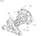
- FIG. 2 is an exploded perspective view showing a pump unit shown in FIG. 1.
- FIG. 1 and FIG. 2 clearly show the main characterized parts of the present invention in order to conceptually and clearly understand the present invention.
- various modifications of the drawings are expected, and there is no need to limit a scope of the present invention to the specific shape shown in the drawings.
- an electric pump may include a motor unit 110, a pump unit 120, a housing unit 130, and a cover unit 140.
- the motor unit 110 provides the pump unit 120 with power and may include a stator 111, a rotor core 112 and a shaft 113.
- the stator 111 may be installed along a circumference of the rotor core 112 with a gap formed therebetween.
- a coil generating a rotating magnetic field is wound around the stator 111 and induces an electrical interaction with the rotor core 112, thereby causing rotation of the rotor core 112.
- the motor unit 110 may include an inverter and an inverter driving part. Also, a print circuit board mounted in the inverter may be directly connected to three-phase (U, V, W) terminals.
- the pump unit 120 is inserted into a pump accommodating part S formed in the housing unit 130 so that power is transmitted from the motor unit 110 to the pump unit to allow the pump unit to pump oil.
- Such pump unit 120 may include an internal rotor 121 and an external rotor 122.
- the shaft 113 is fixedly inserted in a central portion of the internal rotor 121 to directly transmit the power from the motor unit 110 to the internal rotor.
- the housing unit 130 may include a motor housing 131 (see FIG. 1 ) including the motor unit 110 and a pump housing 132 (see FIG. 1 ) forming the pump accommodating part S.
- the pump housing 132 may be aligned and disposed at a front end of the motor housing 131 so that and end portion of the shaft 113 is located at the pump accommodating part S.
- the motor housing 131 and the pump housing 132 may be just classified and described according to a functional characteristic, and the motor housing and the pump housing may be one means in which the two housings are integrally formed with and connected to each other.
- FIG. 3 is a view showing dedendum circles of the internal rotor and the external rotor shown in FIG. 2 .
- the external rotor 122 is disposed outside the internal rotor 121.
- N external lobs 121a may be formed in the circumferential direction of the internal rotor 121, and each of the external lobs extends outward in the radial direction in the internal rotor with respect to a rotational center of the internal rotor.
- N+1 internal lobs 122a may be formed in the external rotor 122, and each of the internal lobs extends inward in the radial direction in the external rotor.
- the internal rotor and the external rotor may be configured to allow the external lobs 121a to be engaged with the internal lobs 122a.
- the external rotor 122 is rotated at a speed ratio of (N+1)/N.
- the pump unit 120 When the internal rotor 121 is rotated, the pump unit 120 has a predetermined eccentric configuration, and a space through which the oil may be conveyed is formed between the internal rotor 121 and the external rotor 122 due to the above eccentric configuration.
- a portion whose volume is increased sucks the ambient oil due to pressure drop and a portion whose volume is decreased discharges the oil due to a pressure increase.
- All the well-known structures may be applied as the above structure of the pump, the further detail description thereon is omitted.
- a diameter (hereinafter, referred to as D1) of a dedendum circle (hereinafter, referred to as C1) of the internal rotor 121 and a diameter (hereinafter, referred to as D2) of a dedendum circle (hereinafter, referred to as C2) of the external rotor 122 become a criteria for forming a pumping space.
- inner circumference surfaces 11 and 21 and outer circumference surfaces 12 and 22 of an inlet port 10 and an outlet port 20 formed in the cover unit 140 and the pump accommodating part S coincide with C1 and C2, respectively.
- the inlet port 10 is expanded to minimize a friction area of a front face of the internal rotor 121, a rear face of the external rotor 122, the pump accommodating part S, and the cover unit 140. This is because, unlike the outlet port 20, there is no need for the inlet port 10 to maintain a high pressure.
- FIG. 4 is a view showing the expanded region of the inlet port formed in the pump accommodating part and
- FIG. 5 is a view showing the expanded region of the inlet port formed in the cover unit.
- the inlet port 10 and the outlet port 20 are formed in the housing unit 130 and the cover unit 140, respectively, to guide a fluid to enable the fluid to be smoothly entered and discharged by the pump unit 120.
- the inlet port 10 and the outlet port 20 as described above are spatially separated from each other to prevent a flow of a fluid due to a pressure difference.
- a friction lose is generated on a contact portion of the pump unit 120, the housing unit 130 and the cover unit 140. Therefore, the friction torque is increased in proportion to the contact area of the pump unit 120, the housing unit 130, and the cover unit 140.
- an original region of the inlet port 10 formed in the housing unit 130 may be additionally expanded by a region represented by "Fa” in FIG. 4 .
- the original region of the inlet port 10 formed in the cover unit 140 may be additionally expanded by the region represented by "Fa” in FIG. 5 . Also, it is possible to additionally expand the original region of the inlet port 10 by the region represented by "Fb” in FIG. 5 .
- FIG. 6 is a view showing an inner diameter of the inlet port formed in the pump accommodating part
- FIG. 7 is a view showing an inner diameter of the inlet port formed in the cover unit.
- a criterion of the expanded region Fa formed inward in the inner circumference surface of the inlet port 10 will be described in detail with reference to FIG. 6 and FIG. 7 .
- the inlet port 10 may be formed in the housing unit 130 and the cover unit 140 in the radial direction and may be limited by an inner circumference surface and an outer circumference surface acting as a boundary. At this time, an inner diameter (hereinafter, referred to as "D3") of the inlet port 10, which is based on an inner circumference surface 11, may be less than D1 of C1.
- D3 may be configured to allow t1 to become 15% to 25% of a diameter of the shaft hole 30. Its purpose is to allow the inlet port 10 to be maximally expanded inward and to secure a structural strength for supporting the shaft 113.
- FIG. 8 is a view showing an outer diameter of the inlet port formed in the pump accommodating part
- FIG. 9 is a view showing an outer diameter of the inlet port formed in the cover unit.
- a criterion of the expanded region Fb formed outward from an outer circumference surface of the inlet port 10 will be described in detail with reference to FIG. 8 and FIG. 9 .
- the inlet port 10 may be configured such that an outer diameter (hereinafter referred to as "D4") of the inlet port 10, which is based on an outer circumference surface 12, may be greater than D2 of C2.
- D4 an outer diameter of the inlet port 10 which is based on an outer circumference surface 12
- an oil ring groove 40 in which an oil ring is inserted is formed in the cover unit 140 in the circumferential direction.
- a distance in the radial direction between the oil ring groove 40 and the outer circumference surface 12 of the inlet port 10 is a thickness (hereinafter referred to as "t2") of an outer wall
- D4 may be configured to allow t2 to be the same as a thickness t4 of the oil ring groove 40.
- an inlet (141 in FIG. 6 ) communicated with the inlet port 10 may be formed and an outlet (142 in FIG. 6 ) communicated with the outlet port 20 may be formed.
- the inlet 141 and the outlet 142 may be configured to face the internal rotor 212 and the external rotor 122.
- the friction region (F in FIG. 6 to FIG. 9 ) is reduced, so that it is possible to reduce the friction torque.
- the friction torque generated among the front face of the internal rotor, the rear face of the external rotor and the housing unit may be reduced to reduce electric power consumption of the electric pump without affecting the performance of the electric pump. Furthermore, it is possible to improve the fuel efficiency of the vehicle to which the present invention is applied.
- the friction area of the pump housing, the cover unit, the internal rotor, and the external rotor is reduced by expanding an area of the inlet port at which there is no need to maintain a high pressure. Therefore, the present invention is advantageous in that the friction torque is reduced and the electric power consumption of the electric pump is reduced.
Landscapes
- Engineering & Computer Science (AREA)
- Mechanical Engineering (AREA)
- General Engineering & Computer Science (AREA)
- Rotary Pumps (AREA)
- Details And Applications Of Rotary Liquid Pumps (AREA)
- Connection Of Motors, Electrical Generators, Mechanical Devices, And The Like (AREA)
Claims (5)
- Une pompe électrique, comprenant :une unité à moteur (110) comprenant un stator (111), un noyau de rotor (112) disposé à l'intérieur du stator (111), et un arbre (113) relié au noyau de rotor (112) ;une unité formant pompe (120) comprenant un rotor interne (121) relié à l'arbre (113) et ayant un lobe externe (121a) formé sur lui et un rotor externe (122) disposé à l'extérieur du rotor interne (121) et ayant un lob interne (122a) formé de façon à venir en engagement avec le lob externe (121a) ;une unité formant boîtier (130) comprenant, formés en elle, un boîtier de moteur (131) comprenant l'unité à moteur (110) et un boîtier de pompe (132) relié au boîtier de moteur (131) et ayant une partie de boîtier de pompe (S), dans laquelle l'unité formant pompe (120) est insérée ; etune unité formant couvercle (140) reliée à l'unité formant boîtier (130) pour couvrir la partie de boîtier de pompe (S),un orifice d'entrée (10) et un orifice de sortie (20) étant formés dans une face inférieure de la partie de boîtier de pompe (S) et une face interne de l'unité formant couvercle (140), et l'orifice d'entrée et l'orifice de sortie (20) sont séparés l'un de l'autre en utilisant une surface de circonférence intérieure et une surface de circonférence extérieure agissant comme limite dans la direction radiale,caractérisée en ce queun diamètre intérieur (D3) de l'orifice d'entrée (10) basé sur la surface de circonférence intérieure est inférieur à un diamètre (D1) d'un cercle de dedendum du rotor intérieur (121), et un diamètre extérieur (D4) de l'orifice d'entrée (10) basé sur la surface de la circonférence extérieure est supérieur à un diamètre (D2) d'un cercle de dedendum du rotor extérieur (122),un diamètre intérieur de l'orifice de sortie (20) étant égal au diamètre (D1) d'un cercle de dedendum du rotor intérieur (121),un diamètre extérieur de l'orifice de sortie (20) étant identique au diamètre (D2) d'un cercle de dedendum du rotor extérieur (122),un diamètre intérieur (D3) de l'orifice d'entrée étant inférieur au diamètre intérieur de l'orifice de sortie (20),un diamètre extérieur (D4) de l'orifice d'entrée étant supérieur au diamètre extérieur de l'orifice de sortie (20).
- La pompe électrique selon la revendication 1, dans laquelle le boîtier de moteur (131) et le boîtier de pompe (132) sont formés d'un seul tenant,
le boîtier de pompe (132) comprenant un trou d'arbre (30) à travers lequel passe l'arbre (113), l'épaisseur d'une paroi intérieure formée à partir du trou d'arbre (30) jusqu'à une surface périphérique intérieure (11) de l'orifice d'entrée (10) représentant 15 à 25% du diamètre du trou d'arbre (30). - La pompe électrique selon la revendication 1, dans laquelle l'unité formant couvercle (140) comprend une rainure annulaire (40) pour huile dans laquelle est introduite une bague pour huile,
l'épaisseur d'une paroi extérieure formée à partir de la rainure annulaire (40) pour huile jusqu'à une surface de circonférence extérieure (12) de l'orifice d'entrée (10) étant supérieure ou égale à une épaisseur de la rainure annulaire (40) pour huile. - La pompe électrique selon la revendication 1, dans laquelle l'unité formant couvercle (140) comprend une entrée communiquant avec l'orifice d'entrée (10) et une sortie communiquant avec l'orifice de sortie (20).
- La pompe électrique selon la revendication 4, dans laquelle l'entrée et la sortie sont tournés vers le rotor interne (121) et le rotor externe (122).
Applications Claiming Priority (1)
| Application Number | Priority Date | Filing Date | Title |
|---|---|---|---|
| KR1020140020284A KR102150609B1 (ko) | 2014-02-21 | 2014-02-21 | 모터 |
Publications (2)
| Publication Number | Publication Date |
|---|---|
| EP2916006A1 EP2916006A1 (fr) | 2015-09-09 |
| EP2916006B1 true EP2916006B1 (fr) | 2019-06-26 |
Family
ID=52477719
Family Applications (1)
| Application Number | Title | Priority Date | Filing Date |
|---|---|---|---|
| EP15155864.0A Active EP2916006B1 (fr) | 2014-02-21 | 2015-02-20 | Pompe électrique |
Country Status (4)
| Country | Link |
|---|---|
| US (2) | US10006458B2 (fr) |
| EP (1) | EP2916006B1 (fr) |
| KR (1) | KR102150609B1 (fr) |
| CN (1) | CN104863845B (fr) |
Families Citing this family (7)
| Publication number | Priority date | Publication date | Assignee | Title |
|---|---|---|---|---|
| CN105186022A (zh) * | 2015-10-12 | 2015-12-23 | 上海合既得动氢机器有限公司 | 一种醇氢电动泵体 |
| DE102016202260A1 (de) * | 2016-02-15 | 2017-08-17 | Bühler Motor GmbH | Pumpenantrieb für die Förderung eines Reduktionsmittels für Kfz-Abgasanlagen, modulare Motor- und Pumpenfamilie zur Bildung unterschiedlicher Pumpenantriebe mit mehreren solcher Elektromotoren |
| KR102311494B1 (ko) * | 2017-09-15 | 2021-10-12 | 엘지이노텍 주식회사 | 전동 펌프 |
| JP7165470B2 (ja) * | 2017-09-13 | 2022-11-04 | エルジー イノテック カンパニー リミテッド | 電動ポンプおよびモーター |
| DE112019005598B4 (de) * | 2018-11-09 | 2025-04-24 | Kyb Corporation | Elektrische Ölpumpe |
| DE102020118012A1 (de) * | 2020-07-08 | 2022-01-13 | Nidec Gpm Gmbh | Pumpe zur Förderung eines Fluids |
| CN114110155B (zh) * | 2021-11-26 | 2023-03-21 | 湖南机油泵股份有限公司 | 一种外装的变速器电子油泵 |
Citations (1)
| Publication number | Priority date | Publication date | Assignee | Title |
|---|---|---|---|---|
| JP2010007516A (ja) * | 2008-06-25 | 2010-01-14 | Hitachi Ltd | 電動オイルポンプ |
Family Cites Families (10)
| Publication number | Priority date | Publication date | Assignee | Title |
|---|---|---|---|---|
| JP2001214869A (ja) * | 2000-01-31 | 2001-08-10 | Sumitomo Electric Ind Ltd | オイルポンプ |
| EP1340912B1 (fr) | 2002-03-01 | 2005-02-02 | Hermann Härle | Machine à engrenage interne avec jeu de dentures |
| JP4136957B2 (ja) * | 2003-03-25 | 2008-08-20 | 住友電工焼結合金株式会社 | 内接歯車式ポンプ |
| JP2006125391A (ja) * | 2004-09-28 | 2006-05-18 | Aisin Seiki Co Ltd | 内接ギヤ型ポンプのロータ構造 |
| KR100772219B1 (ko) * | 2005-12-12 | 2007-11-01 | 엘지전자 주식회사 | 스크롤 압축기의 오일 공급 구조 |
| JP5233984B2 (ja) * | 2007-02-23 | 2013-07-10 | 株式会社ジェイテクト | モータ及び電動ポンプ |
| WO2009149682A2 (fr) | 2008-06-09 | 2009-12-17 | Luk Lamellen Und Kupplungsbau Beteiligungs Kg | Module motopompe |
| DE102009028154A1 (de) * | 2009-07-31 | 2011-02-03 | Robert Bosch Gmbh | Zahnradpumpe |
| US9441628B2 (en) * | 2009-08-04 | 2016-09-13 | Jtekt Corporation | Electric pump unit |
| JP5860695B2 (ja) * | 2011-12-28 | 2016-02-16 | Kyb株式会社 | 電動オイルポンプ |
-
2014
- 2014-02-21 KR KR1020140020284A patent/KR102150609B1/ko active Active
-
2015
- 2015-02-20 US US14/626,974 patent/US10006458B2/en active Active
- 2015-02-20 EP EP15155864.0A patent/EP2916006B1/fr active Active
- 2015-02-25 CN CN201510087409.6A patent/CN104863845B/zh active Active
-
2018
- 2018-06-04 US US15/997,283 patent/US10215173B2/en active Active
Patent Citations (1)
| Publication number | Priority date | Publication date | Assignee | Title |
|---|---|---|---|---|
| JP2010007516A (ja) * | 2008-06-25 | 2010-01-14 | Hitachi Ltd | 電動オイルポンプ |
Also Published As
| Publication number | Publication date |
|---|---|
| KR102150609B1 (ko) | 2020-09-01 |
| US20180283377A1 (en) | 2018-10-04 |
| KR20150098909A (ko) | 2015-08-31 |
| CN104863845A (zh) | 2015-08-26 |
| US10006458B2 (en) | 2018-06-26 |
| US10215173B2 (en) | 2019-02-26 |
| EP2916006A1 (fr) | 2015-09-09 |
| CN104863845B (zh) | 2018-10-16 |
| US20150240813A1 (en) | 2015-08-27 |
Similar Documents
| Publication | Publication Date | Title |
|---|---|---|
| EP2916006B1 (fr) | Pompe électrique | |
| EP2924291B1 (fr) | Pompe électrique | |
| US10337513B2 (en) | Electric-motor-driven liquid pump | |
| JP6369194B2 (ja) | 電動ポンプユニット | |
| JP5493675B2 (ja) | 電動モータおよびロータ | |
| KR102118028B1 (ko) | 전동식 펌프 | |
| US9683567B2 (en) | Electric oil pump | |
| JP4918936B2 (ja) | 電動ポンプ | |
| EP2749737A2 (fr) | Pompe électrique | |
| JP6135225B2 (ja) | ポンプ | |
| KR102118031B1 (ko) | 전동 펌프 | |
| US20150086393A1 (en) | Oil pump for vehicle | |
| JP6794745B2 (ja) | 流体圧ポンプ | |
| KR102405642B1 (ko) | 전동 펌프 | |
| JP2012026349A (ja) | 電動ポンプユニット | |
| JP2016223323A (ja) | 燃料ポンプ | |
| JP6418059B2 (ja) | 燃料ポンプ | |
| HK1234808A1 (en) | Electric-motor-driven liquid pump |
Legal Events
| Date | Code | Title | Description |
|---|---|---|---|
| PUAI | Public reference made under article 153(3) epc to a published international application that has entered the european phase |
Free format text: ORIGINAL CODE: 0009012 |
|
| AK | Designated contracting states |
Kind code of ref document: A1 Designated state(s): AL AT BE BG CH CY CZ DE DK EE ES FI FR GB GR HR HU IE IS IT LI LT LU LV MC MK MT NL NO PL PT RO RS SE SI SK SM TR |
|
| AX | Request for extension of the european patent |
Extension state: BA ME |
|
| 17P | Request for examination filed |
Effective date: 20160309 |
|
| RBV | Designated contracting states (corrected) |
Designated state(s): AL AT BE BG CH CY CZ DE DK EE ES FI FR GB GR HR HU IE IS IT LI LT LU LV MC MK MT NL NO PL PT RO RS SE SI SK SM TR |
|
| RAP1 | Party data changed (applicant data changed or rights of an application transferred) |
Owner name: LG INNOTEK CO., LTD. |
|
| STAA | Information on the status of an ep patent application or granted ep patent |
Free format text: STATUS: EXAMINATION IS IN PROGRESS |
|
| 17Q | First examination report despatched |
Effective date: 20180404 |
|
| GRAP | Despatch of communication of intention to grant a patent |
Free format text: ORIGINAL CODE: EPIDOSNIGR1 |
|
| STAA | Information on the status of an ep patent application or granted ep patent |
Free format text: STATUS: GRANT OF PATENT IS INTENDED |
|
| INTG | Intention to grant announced |
Effective date: 20190121 |
|
| GRAS | Grant fee paid |
Free format text: ORIGINAL CODE: EPIDOSNIGR3 |
|
| GRAA | (expected) grant |
Free format text: ORIGINAL CODE: 0009210 |
|
| STAA | Information on the status of an ep patent application or granted ep patent |
Free format text: STATUS: THE PATENT HAS BEEN GRANTED |
|
| AK | Designated contracting states |
Kind code of ref document: B1 Designated state(s): AL AT BE BG CH CY CZ DE DK EE ES FI FR GB GR HR HU IE IS IT LI LT LU LV MC MK MT NL NO PL PT RO RS SE SI SK SM TR |
|
| REG | Reference to a national code |
Ref country code: GB Ref legal event code: FG4D |
|
| REG | Reference to a national code |
Ref country code: CH Ref legal event code: EP |
|
| REG | Reference to a national code |
Ref country code: DE Ref legal event code: R096 Ref document number: 602015032561 Country of ref document: DE |
|
| REG | Reference to a national code |
Ref country code: AT Ref legal event code: REF Ref document number: 1148588 Country of ref document: AT Kind code of ref document: T Effective date: 20190715 |
|
| REG | Reference to a national code |
Ref country code: IE Ref legal event code: FG4D |
|
| REG | Reference to a national code |
Ref country code: NL Ref legal event code: MP Effective date: 20190626 |
|
| PG25 | Lapsed in a contracting state [announced via postgrant information from national office to epo] |
Ref country code: HR Free format text: LAPSE BECAUSE OF FAILURE TO SUBMIT A TRANSLATION OF THE DESCRIPTION OR TO PAY THE FEE WITHIN THE PRESCRIBED TIME-LIMIT Effective date: 20190626 Ref country code: LT Free format text: LAPSE BECAUSE OF FAILURE TO SUBMIT A TRANSLATION OF THE DESCRIPTION OR TO PAY THE FEE WITHIN THE PRESCRIBED TIME-LIMIT Effective date: 20190626 Ref country code: SE Free format text: LAPSE BECAUSE OF FAILURE TO SUBMIT A TRANSLATION OF THE DESCRIPTION OR TO PAY THE FEE WITHIN THE PRESCRIBED TIME-LIMIT Effective date: 20190626 Ref country code: FI Free format text: LAPSE BECAUSE OF FAILURE TO SUBMIT A TRANSLATION OF THE DESCRIPTION OR TO PAY THE FEE WITHIN THE PRESCRIBED TIME-LIMIT Effective date: 20190626 Ref country code: AL Free format text: LAPSE BECAUSE OF FAILURE TO SUBMIT A TRANSLATION OF THE DESCRIPTION OR TO PAY THE FEE WITHIN THE PRESCRIBED TIME-LIMIT Effective date: 20190626 Ref country code: NO Free format text: LAPSE BECAUSE OF FAILURE TO SUBMIT A TRANSLATION OF THE DESCRIPTION OR TO PAY THE FEE WITHIN THE PRESCRIBED TIME-LIMIT Effective date: 20190926 |
|
| REG | Reference to a national code |
Ref country code: LT Ref legal event code: MG4D |
|
| PG25 | Lapsed in a contracting state [announced via postgrant information from national office to epo] |
Ref country code: BG Free format text: LAPSE BECAUSE OF FAILURE TO SUBMIT A TRANSLATION OF THE DESCRIPTION OR TO PAY THE FEE WITHIN THE PRESCRIBED TIME-LIMIT Effective date: 20190926 Ref country code: GR Free format text: LAPSE BECAUSE OF FAILURE TO SUBMIT A TRANSLATION OF THE DESCRIPTION OR TO PAY THE FEE WITHIN THE PRESCRIBED TIME-LIMIT Effective date: 20190927 Ref country code: LV Free format text: LAPSE BECAUSE OF FAILURE TO SUBMIT A TRANSLATION OF THE DESCRIPTION OR TO PAY THE FEE WITHIN THE PRESCRIBED TIME-LIMIT Effective date: 20190626 Ref country code: RS Free format text: LAPSE BECAUSE OF FAILURE TO SUBMIT A TRANSLATION OF THE DESCRIPTION OR TO PAY THE FEE WITHIN THE PRESCRIBED TIME-LIMIT Effective date: 20190626 |
|
| REG | Reference to a national code |
Ref country code: AT Ref legal event code: MK05 Ref document number: 1148588 Country of ref document: AT Kind code of ref document: T Effective date: 20190626 |
|
| PG25 | Lapsed in a contracting state [announced via postgrant information from national office to epo] |
Ref country code: EE Free format text: LAPSE BECAUSE OF FAILURE TO SUBMIT A TRANSLATION OF THE DESCRIPTION OR TO PAY THE FEE WITHIN THE PRESCRIBED TIME-LIMIT Effective date: 20190626 Ref country code: AT Free format text: LAPSE BECAUSE OF FAILURE TO SUBMIT A TRANSLATION OF THE DESCRIPTION OR TO PAY THE FEE WITHIN THE PRESCRIBED TIME-LIMIT Effective date: 20190626 Ref country code: CZ Free format text: LAPSE BECAUSE OF FAILURE TO SUBMIT A TRANSLATION OF THE DESCRIPTION OR TO PAY THE FEE WITHIN THE PRESCRIBED TIME-LIMIT Effective date: 20190626 Ref country code: NL Free format text: LAPSE BECAUSE OF FAILURE TO SUBMIT A TRANSLATION OF THE DESCRIPTION OR TO PAY THE FEE WITHIN THE PRESCRIBED TIME-LIMIT Effective date: 20190626 Ref country code: RO Free format text: LAPSE BECAUSE OF FAILURE TO SUBMIT A TRANSLATION OF THE DESCRIPTION OR TO PAY THE FEE WITHIN THE PRESCRIBED TIME-LIMIT Effective date: 20190626 Ref country code: PT Free format text: LAPSE BECAUSE OF FAILURE TO SUBMIT A TRANSLATION OF THE DESCRIPTION OR TO PAY THE FEE WITHIN THE PRESCRIBED TIME-LIMIT Effective date: 20191028 Ref country code: SK Free format text: LAPSE BECAUSE OF FAILURE TO SUBMIT A TRANSLATION OF THE DESCRIPTION OR TO PAY THE FEE WITHIN THE PRESCRIBED TIME-LIMIT Effective date: 20190626 |
|
| PG25 | Lapsed in a contracting state [announced via postgrant information from national office to epo] |
Ref country code: IS Free format text: LAPSE BECAUSE OF FAILURE TO SUBMIT A TRANSLATION OF THE DESCRIPTION OR TO PAY THE FEE WITHIN THE PRESCRIBED TIME-LIMIT Effective date: 20191026 Ref country code: IT Free format text: LAPSE BECAUSE OF FAILURE TO SUBMIT A TRANSLATION OF THE DESCRIPTION OR TO PAY THE FEE WITHIN THE PRESCRIBED TIME-LIMIT Effective date: 20190626 Ref country code: SM Free format text: LAPSE BECAUSE OF FAILURE TO SUBMIT A TRANSLATION OF THE DESCRIPTION OR TO PAY THE FEE WITHIN THE PRESCRIBED TIME-LIMIT Effective date: 20190626 Ref country code: ES Free format text: LAPSE BECAUSE OF FAILURE TO SUBMIT A TRANSLATION OF THE DESCRIPTION OR TO PAY THE FEE WITHIN THE PRESCRIBED TIME-LIMIT Effective date: 20190626 |
|
| PG25 | Lapsed in a contracting state [announced via postgrant information from national office to epo] |
Ref country code: TR Free format text: LAPSE BECAUSE OF FAILURE TO SUBMIT A TRANSLATION OF THE DESCRIPTION OR TO PAY THE FEE WITHIN THE PRESCRIBED TIME-LIMIT Effective date: 20190626 |
|
| PG25 | Lapsed in a contracting state [announced via postgrant information from national office to epo] |
Ref country code: DK Free format text: LAPSE BECAUSE OF FAILURE TO SUBMIT A TRANSLATION OF THE DESCRIPTION OR TO PAY THE FEE WITHIN THE PRESCRIBED TIME-LIMIT Effective date: 20190626 Ref country code: PL Free format text: LAPSE BECAUSE OF FAILURE TO SUBMIT A TRANSLATION OF THE DESCRIPTION OR TO PAY THE FEE WITHIN THE PRESCRIBED TIME-LIMIT Effective date: 20190626 |
|
| PG25 | Lapsed in a contracting state [announced via postgrant information from national office to epo] |
Ref country code: IS Free format text: LAPSE BECAUSE OF FAILURE TO SUBMIT A TRANSLATION OF THE DESCRIPTION OR TO PAY THE FEE WITHIN THE PRESCRIBED TIME-LIMIT Effective date: 20200224 |
|
| REG | Reference to a national code |
Ref country code: DE Ref legal event code: R097 Ref document number: 602015032561 Country of ref document: DE |
|
| PLBE | No opposition filed within time limit |
Free format text: ORIGINAL CODE: 0009261 |
|
| STAA | Information on the status of an ep patent application or granted ep patent |
Free format text: STATUS: NO OPPOSITION FILED WITHIN TIME LIMIT |
|
| PG2D | Information on lapse in contracting state deleted |
Ref country code: IS |
|
| 26N | No opposition filed |
Effective date: 20200603 |
|
| PG25 | Lapsed in a contracting state [announced via postgrant information from national office to epo] |
Ref country code: SI Free format text: LAPSE BECAUSE OF FAILURE TO SUBMIT A TRANSLATION OF THE DESCRIPTION OR TO PAY THE FEE WITHIN THE PRESCRIBED TIME-LIMIT Effective date: 20190626 |
|
| REG | Reference to a national code |
Ref country code: CH Ref legal event code: PL |
|
| REG | Reference to a national code |
Ref country code: BE Ref legal event code: MM Effective date: 20200229 |
|
| PG25 | Lapsed in a contracting state [announced via postgrant information from national office to epo] |
Ref country code: LU Free format text: LAPSE BECAUSE OF NON-PAYMENT OF DUE FEES Effective date: 20200220 Ref country code: MC Free format text: LAPSE BECAUSE OF FAILURE TO SUBMIT A TRANSLATION OF THE DESCRIPTION OR TO PAY THE FEE WITHIN THE PRESCRIBED TIME-LIMIT Effective date: 20190626 |
|
| PG25 | Lapsed in a contracting state [announced via postgrant information from national office to epo] |
Ref country code: CH Free format text: LAPSE BECAUSE OF NON-PAYMENT OF DUE FEES Effective date: 20200229 Ref country code: LI Free format text: LAPSE BECAUSE OF NON-PAYMENT OF DUE FEES Effective date: 20200229 |
|
| PG25 | Lapsed in a contracting state [announced via postgrant information from national office to epo] |
Ref country code: IE Free format text: LAPSE BECAUSE OF NON-PAYMENT OF DUE FEES Effective date: 20200220 |
|
| PG25 | Lapsed in a contracting state [announced via postgrant information from national office to epo] |
Ref country code: BE Free format text: LAPSE BECAUSE OF NON-PAYMENT OF DUE FEES Effective date: 20200229 |
|
| PG25 | Lapsed in a contracting state [announced via postgrant information from national office to epo] |
Ref country code: MT Free format text: LAPSE BECAUSE OF FAILURE TO SUBMIT A TRANSLATION OF THE DESCRIPTION OR TO PAY THE FEE WITHIN THE PRESCRIBED TIME-LIMIT Effective date: 20190626 Ref country code: CY Free format text: LAPSE BECAUSE OF FAILURE TO SUBMIT A TRANSLATION OF THE DESCRIPTION OR TO PAY THE FEE WITHIN THE PRESCRIBED TIME-LIMIT Effective date: 20190626 |
|
| PG25 | Lapsed in a contracting state [announced via postgrant information from national office to epo] |
Ref country code: MK Free format text: LAPSE BECAUSE OF FAILURE TO SUBMIT A TRANSLATION OF THE DESCRIPTION OR TO PAY THE FEE WITHIN THE PRESCRIBED TIME-LIMIT Effective date: 20190626 |
|
| PGFP | Annual fee paid to national office [announced via postgrant information from national office to epo] |
Ref country code: GB Payment date: 20251222 Year of fee payment: 12 |
|
| PGFP | Annual fee paid to national office [announced via postgrant information from national office to epo] |
Ref country code: FR Payment date: 20251223 Year of fee payment: 12 |
|
| PGFP | Annual fee paid to national office [announced via postgrant information from national office to epo] |
Ref country code: DE Payment date: 20251222 Year of fee payment: 12 |