EP2916116B1 - Dispositif d'acquisition de caractéristique spectrale, dispositif d'évaluation d'image, et appareil de formation d'image - Google Patents
Dispositif d'acquisition de caractéristique spectrale, dispositif d'évaluation d'image, et appareil de formation d'image Download PDFInfo
- Publication number
- EP2916116B1 EP2916116B1 EP15154809.6A EP15154809A EP2916116B1 EP 2916116 B1 EP2916116 B1 EP 2916116B1 EP 15154809 A EP15154809 A EP 15154809A EP 2916116 B1 EP2916116 B1 EP 2916116B1
- Authority
- EP
- European Patent Office
- Prior art keywords
- spectral characteristic
- image
- light
- acquisition device
- calibration
- Prior art date
- Legal status (The legal status is an assumption and is not a legal conclusion. Google has not performed a legal analysis and makes no representation as to the accuracy of the status listed.)
- Active
Links
Images








Classifications
-
- G—PHYSICS
- G06—COMPUTING OR CALCULATING; COUNTING
- G06K—GRAPHICAL DATA READING; PRESENTATION OF DATA; RECORD CARRIERS; HANDLING RECORD CARRIERS
- G06K15/00—Arrangements for producing a permanent visual presentation of the output data, e.g. computer output printers
- G06K15/02—Arrangements for producing a permanent visual presentation of the output data, e.g. computer output printers using printers
- G06K15/18—Conditioning data for presenting it to the physical printing elements
- G06K15/1867—Post-processing of the composed and rasterized print image
- G06K15/1872—Image enhancement
- G06K15/1878—Adjusting colours
-
- G—PHYSICS
- G01—MEASURING; TESTING
- G01J—MEASUREMENT OF INTENSITY, VELOCITY, SPECTRAL CONTENT, POLARISATION, PHASE OR PULSE CHARACTERISTICS OF INFRARED, VISIBLE OR ULTRAVIOLET LIGHT; COLORIMETRY; RADIATION PYROMETRY
- G01J3/00—Spectrometry; Spectrophotometry; Monochromators; Measuring colours
- G01J3/28—Investigating the spectrum
-
- G—PHYSICS
- G01—MEASURING; TESTING
- G01J—MEASUREMENT OF INTENSITY, VELOCITY, SPECTRAL CONTENT, POLARISATION, PHASE OR PULSE CHARACTERISTICS OF INFRARED, VISIBLE OR ULTRAVIOLET LIGHT; COLORIMETRY; RADIATION PYROMETRY
- G01J3/00—Spectrometry; Spectrophotometry; Monochromators; Measuring colours
- G01J3/28—Investigating the spectrum
- G01J3/2803—Investigating the spectrum using photoelectric array detector
-
- G—PHYSICS
- G01—MEASURING; TESTING
- G01J—MEASUREMENT OF INTENSITY, VELOCITY, SPECTRAL CONTENT, POLARISATION, PHASE OR PULSE CHARACTERISTICS OF INFRARED, VISIBLE OR ULTRAVIOLET LIGHT; COLORIMETRY; RADIATION PYROMETRY
- G01J3/00—Spectrometry; Spectrophotometry; Monochromators; Measuring colours
- G01J3/46—Measurement of colour; Colour measuring devices, e.g. colorimeters
- G01J3/52—Measurement of colour; Colour measuring devices, e.g. colorimeters using colour charts
-
- G—PHYSICS
- G01—MEASURING; TESTING
- G01J—MEASUREMENT OF INTENSITY, VELOCITY, SPECTRAL CONTENT, POLARISATION, PHASE OR PULSE CHARACTERISTICS OF INFRARED, VISIBLE OR ULTRAVIOLET LIGHT; COLORIMETRY; RADIATION PYROMETRY
- G01J3/00—Spectrometry; Spectrophotometry; Monochromators; Measuring colours
- G01J3/46—Measurement of colour; Colour measuring devices, e.g. colorimeters
- G01J3/52—Measurement of colour; Colour measuring devices, e.g. colorimeters using colour charts
- G01J3/524—Calibration of colorimeters
-
- G—PHYSICS
- G01—MEASURING; TESTING
- G01N—INVESTIGATING OR ANALYSING MATERIALS BY DETERMINING THEIR CHEMICAL OR PHYSICAL PROPERTIES
- G01N21/00—Investigating or analysing materials by the use of optical means, i.e. using sub-millimetre waves, infrared, visible or ultraviolet light
- G01N21/17—Systems in which incident light is modified in accordance with the properties of the material investigated
- G01N21/25—Colour; Spectral properties, i.e. comparison of effect of material on the light at two or more different wavelengths or wavelength bands
- G01N21/27—Colour; Spectral properties, i.e. comparison of effect of material on the light at two or more different wavelengths or wavelength bands using photo-electric detection ; circuits for computing concentration
- G01N21/274—Calibration, base line adjustment, drift correction
- G01N21/276—Calibration, base line adjustment, drift correction with alternation of sample and standard in optical path
-
- G—PHYSICS
- G01—MEASURING; TESTING
- G01N—INVESTIGATING OR ANALYSING MATERIALS BY DETERMINING THEIR CHEMICAL OR PHYSICAL PROPERTIES
- G01N21/00—Investigating or analysing materials by the use of optical means, i.e. using sub-millimetre waves, infrared, visible or ultraviolet light
- G01N21/17—Systems in which incident light is modified in accordance with the properties of the material investigated
- G01N21/25—Colour; Spectral properties, i.e. comparison of effect of material on the light at two or more different wavelengths or wavelength bands
- G01N21/27—Colour; Spectral properties, i.e. comparison of effect of material on the light at two or more different wavelengths or wavelength bands using photo-electric detection ; circuits for computing concentration
- G01N21/274—Calibration, base line adjustment, drift correction
- G01N21/278—Constitution of standards
-
- G—PHYSICS
- G01—MEASURING; TESTING
- G01N—INVESTIGATING OR ANALYSING MATERIALS BY DETERMINING THEIR CHEMICAL OR PHYSICAL PROPERTIES
- G01N21/00—Investigating or analysing materials by the use of optical means, i.e. using sub-millimetre waves, infrared, visible or ultraviolet light
- G01N21/17—Systems in which incident light is modified in accordance with the properties of the material investigated
- G01N21/47—Scattering, i.e. diffuse reflection
- G01N21/4788—Diffraction
-
- G—PHYSICS
- G06—COMPUTING OR CALCULATING; COUNTING
- G06K—GRAPHICAL DATA READING; PRESENTATION OF DATA; RECORD CARRIERS; HANDLING RECORD CARRIERS
- G06K15/00—Arrangements for producing a permanent visual presentation of the output data, e.g. computer output printers
- G06K15/02—Arrangements for producing a permanent visual presentation of the output data, e.g. computer output printers using printers
- G06K15/027—Test patterns and calibration
-
- H—ELECTRICITY
- H04—ELECTRIC COMMUNICATION TECHNIQUE
- H04N—PICTORIAL COMMUNICATION, e.g. TELEVISION
- H04N1/00—Scanning, transmission or reproduction of documents or the like, e.g. facsimile transmission; Details thereof
- H04N1/46—Colour picture communication systems
- H04N1/56—Processing of colour picture signals
- H04N1/60—Colour correction or control
- H04N1/6027—Correction or control of colour gradation or colour contrast
-
- H—ELECTRICITY
- H04—ELECTRIC COMMUNICATION TECHNIQUE
- H04N—PICTORIAL COMMUNICATION, e.g. TELEVISION
- H04N1/00—Scanning, transmission or reproduction of documents or the like, e.g. facsimile transmission; Details thereof
- H04N1/46—Colour picture communication systems
- H04N1/56—Processing of colour picture signals
- H04N1/60—Colour correction or control
- H04N1/603—Colour correction or control controlled by characteristics of the picture signal generator or the picture reproducer
- H04N1/6033—Colour correction or control controlled by characteristics of the picture signal generator or the picture reproducer using test pattern analysis
- H04N1/6041—Colour correction or control controlled by characteristics of the picture signal generator or the picture reproducer using test pattern analysis for controlling uniformity of color across image area
-
- H—ELECTRICITY
- H04—ELECTRIC COMMUNICATION TECHNIQUE
- H04N—PICTORIAL COMMUNICATION, e.g. TELEVISION
- H04N1/00—Scanning, transmission or reproduction of documents or the like, e.g. facsimile transmission; Details thereof
- H04N1/46—Colour picture communication systems
- H04N1/56—Processing of colour picture signals
- H04N1/60—Colour correction or control
- H04N1/603—Colour correction or control controlled by characteristics of the picture signal generator or the picture reproducer
- H04N1/6033—Colour correction or control controlled by characteristics of the picture signal generator or the picture reproducer using test pattern analysis
- H04N1/6044—Colour correction or control controlled by characteristics of the picture signal generator or the picture reproducer using test pattern analysis involving a sensor integrated in the machine or otherwise specifically adapted to read the test pattern
-
- H—ELECTRICITY
- H04—ELECTRIC COMMUNICATION TECHNIQUE
- H04N—PICTORIAL COMMUNICATION, e.g. TELEVISION
- H04N1/00—Scanning, transmission or reproduction of documents or the like, e.g. facsimile transmission; Details thereof
- H04N1/46—Colour picture communication systems
- H04N1/56—Processing of colour picture signals
- H04N1/60—Colour correction or control
- H04N1/6097—Colour correction or control depending on the characteristics of the output medium, e.g. glossy paper, matt paper, transparency or fabrics
Definitions
- An aspect of the present invention relates to at least one of a spectral characteristic acquisition device, an image evaluation device, and an image formation apparatus.
- an image formation apparatus such as a printing apparatus or a printer
- a control of color tone such as color stability or color reproducibility.
- an image formation apparatus has been realized that installs a spectrometer such as a spectrophotometer for a control of color tone.
- a colorimetric value such as XYZ or L*a*b* defined in CIE (International Commission on Illumination) is obtained from a spectral characteristic of diffused or reflected light from a print surface as measured by a spectrometer to execute check of color tone of a print or adjustment of an image formation process.
- CIE International Commission on Illumination
- a spectrometer for measuring visible light detects light in a wavelength range of 400 - 700 nm for each wavelength band with a pitch of 10 nm and outputs 31 or more digitized values.
- a measurement of a spectral characteristic needs a certain period of time because diffused or reflected from a surface to be measured is temporally and spatially divided into 31 or more to acquire a light intensity signal. Therefore, for example, in a case where an in-line measurement is executed for an output image at a rate corresponding to a printing speed thereof in an image formation apparatus for executing high-speed printing, a rate of detection may be insufficient so that application thereof may be difficult.
- a method that detects light in a comparatively few or about 3 - 16 wavelength bands referred to as a multiband by a spectrometer and estimates a spectral characteristic of a measurement object from a detection result thereof (for example, see Norimichi Tsumura, Hideaki Haneishi, Youichi Miyake, "Estimation of Spectral Reflectances from Multi-Band Images by Multiple Regression Analysis", Japanese Journal of Optics, Vol. 27, No. 7, pp. 384-391 (1998 )).
- a method it is possible to reduce a period of time necessary for detection because the number of wavelength bands to be detected is small, and it is also possible to be applied to a field required for a high-speed measurement such as an in-line measurement for a printed image. Furthermore, for example, it is possible to estimate, at high precision, a spectral characteristic of a measurement object provided in such a manner that it is possible to acquire statistical information with respect to a spectral characteristic thereof preliminarily, such as a printed image with a color reproduced by a combination of about 4 kinds of color materials.
- estimation of a spectral characteristic is executed by using a transformation matrix that is obtained from a measurement result for a standard sample with a known spectral characteristic. It is preferable for a transformation matrix to be obtained from a standard sample that has a feature approximating a spectral characteristic of a measurement object, in order to estimate such a spectral characteristic at high precision. Furthermore, it is preferable to set a plurality of transformation matrices dependent on a feature of a measurement object or the like in such a manner that it is possible to handle a variety of measurement objects. However, it is necessary to prepare and measure an enormous number of standard samples and execute an operation process thereof in order to obtain a plurality of transformation matrices, so that a lot of labor and coat is required.
- EP 2 568 267 A1 discloses a spectral sensor for printed images including a calculating part storing a transformation matrix used for calculating a spectral characteristic corresponding to electric signals of a diffraction pattern group. Based on those electric signals, a spectral characteristic at locations of an image-carrying medium corresponding to apertures of the diffraction pattern group are calculated.
- EP 0 301 506 A2 discloses an image scanning and reading apparatus having calibration reference portions.
- US 2012/0070200 A1 discloses an image scanner which includes: a light source that irradiates, with light, a recording medium on which an image is formed; a light receiving portion that receives light reflected by the recording medium; a generating portion that generates a light amount value from the light received by the light receiving portion; a measuring portion in which plural reflecting surfaces are disposed, the reflecting surfaces respectively having predetermined colors different from each other; and a processing portion that derives a correlation formula from a light amount value generated at predetermined reference time and from a light amount value generated when the reflecting surfaces in the measuring portion are irradiated with the light from the light source, the correlation formula expressing a time-varying change in the light source.
- JP 2002-290685 discloses an image reading unit which is capable of improving the images of both the front and rear of a manuscript in quality and uniformity by improving an input element located on is rear side in correlation accuracy.
- JP 2010-114498 discloses an image forming apparatus and an image reading apparatus, capable of continuously reading reflection lights from at least two kinds of reference planes.
- a spectral characteristic acquisition device as defined in claim 1.
- an image evaluation device as defined in claim 3.
- an image formation apparatus as defined in claim 4.
- a spectral characteristic in the present application refers to an amount of light for diffused or reflected light being represented as a function of a wavelength thereof and includes a spectral reflectance distribution.
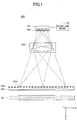
- FIG. 1 and FIG. 2 illustrate a configuration example of a spectral characteristic acquisition device 100 according to first embodiment.
- FIG. 1 is a front view of the spectral characteristic acquisition device 100 and
- FIG. 2 is a side view of the spectral characteristic acquisition device 100.
- an X-direction indicates a direction of alignment of pixels of a line sensor 107 that is a light-receiving means
- a Y-direction indicates a direction orthogonal to the direction of alignment of pixels on a light-receiving surface of the line sensor 107
- a Z-direction indicates a direction orthogonal to the direction of alignment of pixels of the line sensor 107 and perpendicular to the light-receiving surface.
- broken lines illustrated in FIG. 1 and FIG. 2 schematically illustrates a representative light paths after diffusion or reflection of light that irradiates a measurement object (an object) 10.
- the spectral characteristic acquisition device 100 has a line illumination light source 101 and a collimator lens 102 (non-illustrated in FIG. 1 ), as a light irradiation means, a micro-lens array 103, a hole array 104, an imaging optical system 105, a diffraction element 106 as a diffraction means, the line sensor 107 as a light-receiving means, and an operation means 110.
- the line illumination light source 101 and the collimator lens 102 irradiate the measurement object 10 with a spectral characteristic to be measured, with line-shaped light spreading in a width direction (X-direction).
- the measurement object 10 is a recording medium with an image formed on a surface thereof or the like.
- the line illumination light source 101 is a white Light Emitting Diode (LED) array that has an intensity with respect to approximately a gamut of visible light.
- the line illumination light source 101 may be a fluorescent lamp such as a cold-cathode tube, a lamp light source, or the like.
- the collimator lens 102 collimates (as generally collimated light) or condenses, and irradiates the measurement object 10 with, light emitted from the line illumination light source 101.
- a configuration example that has the line illumination light source 101 and the collimator lens 102 is illustrated as a light irradiation means, a configuration may be provided in such a manner that the collimator lens 102 is omitted.
- the micro-lens array 103 images light diffused or reflected from the measurement object 10 irradiated with light onto the hole array 104.
- accurate imaging onto the hole array 104 is not necessarily required, and a defocussed state or an infinite system may be provided.
- a first imaging means may be a gradient-index-type lens array such as a Selfoc (registered trademark) lens array or an imaging optical system composed of a plurality of lenses or mirrors, instead of the micro-lens array 103.
- the hole array 104 is such that a plurality of apertures 104a are formed in line in an X-direction as illustrated in FIG. 1 .
- the hole array 104 is such that a part other than the apertures 104a are a light-blocking part that blocks light, and light imaged by the micro-lens array 103 onto the hole array 104 transmits through the apertures 104a to the imaging optical system 105.
- the hole array 104 may be a metal or black resin material with the apertures 104a formed thereon, a glass, a transparent resin, or the like, with a metallic film, a black resin, or the like, patterned and applied thereon, or the like.
- a plurality of apertures may be aligned in two or more lines.
- the imaging optical system 105 are composed of a plurality of lenses and images light that has transmitted through the hole array 104, through the diffraction element 106 onto a light-receiving surface of the line sensor 107.
- the imaging optical system 105 may be lenses used for a general scanner optical system, or industrially used lenses for line sensor.
- An optical system for the spectral characteristic acquisition device 100 is a so-called 45/0 optical system in such a manner that illumination light emitted from the line illumination light source 101 is obliquely incident on the measurement object 10 at about 45 degrees and the line sensor 170 receives light diffused or reflected from the measurement object 10 in a Z-direction, as illustrated in FIG. 2 .
- an optical system for the spectral characteristic acquisition device 100 may be a so-called 0/45 optical system in such a manner that illumination light emitted from the line illumination light source 10 is perpendicularly incident on the measurement object 10 and the line sensor 107 receives light diffused or reflected from the measurement object 10 in a direction at 45 degrees, or the like.
- the line sensor 107 is one example of a light-receiving means, is composed of a plurality of pixels, and outputs an electric signal that corresponds to incident light diffracted or reflected from the diffraction element 106 for each of different wavelength bands.
- the line sensor 107 is a Metal Oxide Semiconductor (MOS) Device, a Complementary Metal Oxide Semiconductor (CMOS) Device, a Charge Coupled Device (CCD), a Photo-Diode Array (PDA), or the like.
- MOS Metal Oxide Semiconductor
- CMOS Complementary Metal Oxide Semiconductor
- CCD Charge Coupled Device
- PDA Photo-Diode Array
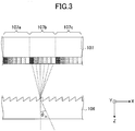
- FIG. 3 is a diagram that schematically illustrates a pixel structure of the line sensor 107.
- the line sensor 107 has a pixel structure wherein a plurality of pixels are aligned in a line in an X-direction.
- the line sensor 107 is a spectral sensor array wherein a first spectral sensor 107a, a second spectral sensor 107b, a third spectral sensor 107c, and the like (a plurality thereof) are further aligned wherein n pixels are provided as one group.
- Each of the first spectral sensor 107a, the second spectral sensor 107b, the third spectral sensor 107c, and the like has N pixels and receives light of a diffraction image different from one another.
- a plurality of pixels of the line sensor 107 are not limited to a structure of pixels aligned in a line but may be aligned in two or more lines.
- An aperture 104a of the hole array 104 and N pixels of a spectral sensor of the line sensor 107 have an imaging relationship in such a manner that light that has transmitted through one aperture 104a of the hole array 104 is incident on N pixels of one spectral sensor of the line sensor 107.
- the diffraction element 106 is such that a saw-tooth shape as illustrated in FIG. 3 is formed on a transparent substrate at a predetermined interval.
- a saw-tooth portion of the diffraction element 106 may be another shape such as a step shape.
- p is a period of a saw-tooth shape of the diffraction element 106
- m is an order of diffraction that is caused by the diffraction element 106, wherein it is possible to be a positive or negative integer value.
- light diffracted by the diffraction element 106 may be such that 0th order light, a 2nd order diffraction image, a diffraction image that has transmitted through an adjacent aperture, or the like overlaps on a light-receiving surface of the line sensor 107.
- crosstalk is caused so that acquisition of an accurate spectral characteristic is difficult.
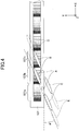
- a configuration is provided in such a manner that the diffraction element 106 is rotated in an XY-plane or an angle of a tooth of the diffraction element 106 is set appropriately so that a diffraction direction of diffracted light and a direction of pixel alignment of the line sensor 107 have a predetermined angle ⁇ .
- a diffraction image is incident so as to have or incline by an angle ⁇ with respect to a direction of pixel alignment of the line sensor 107 as illustrated in FIG. 4 , so that crosstalk caused by overlapping of diffraction images is prevented.
- a +1st order diffraction image B for each aperture of the hole array 104 is imaged on the line sensor 107 while an unrequired non-diffraction image A (0th order diffraction image), a -1st order diffraction image C, a +2nd order diffraction image D, a -2nd order diffraction image E, and the like, are imaged at positions distant from pixels of the line sensor 107.
- the spectral characteristic acquisition device 100 excludes crosstalk among diffraction images, wherein it is possible to obtain a spectral characteristic of the measurement object 10 from a +1st order diffraction image B.
- a +1st order diffraction image B may simply be referred to as a diffraction image in the following descriptions.
- the operation means 110 estimates and calculates a spectral characteristic of the measurement object 10, from an electric signal that is outputted from the line sensor 107, by using a transformation matrix.
- the operation means 110 includes a CPU, a ROM, a main memory, and the like, wherein a program recorded in the ROM or the like is read out in the main memory and executed by the CPU to realize a function.
- the operation means 110 may be physically composed of a plurality of devices.
- FIG. 5 is a diagram that illustrates a functional configuration of the operation means 110 in the first embodiment.
- the operation means 110 has an operation part 111 that has a sensor data input part 112, a transformation matrix calculation part 113 as a transformation matrix correction means, a spectral characteristic calculation part 114 as a spectral characteristic calculation means, and a correction coefficient calculation part 115 as a first correction coefficient calculation means or a second correction coefficient calculation means, and a storage part 116 that has a reference data storage part 117, a sensor data storage part 118, and a transformation matrix storage part 119.
- a function of each part that is had by the operation means 110 will be described below, and a method will be described that estimates and calculates a spectral reflectance distribution as a spectral characteristic of the measurement object 10.
- an electric signal is outputted from each spectral sensor of the line sensor 107 that has received light of a diffraction image and is inputted into the sensor data input part 112 of the operation means 110 as sensor data.
- the spectral characteristic calculation part 114 calculates a spectral characteristic of the measurement object 10 from the sensor data by using a transformation matrix that is preliminarily stored in the transformation matrix storage part 119.
- a method will be described that estimates and calculates a spectral reflectance distribution as a spectral characteristic from sensor data for one spectral sensor of the line sensor 107 in the spectral characteristic calculation part 114 in the present embodiment.
- a spectral characteristic may be obtained by a method that is different from a method that will be described below.
- a transformation matrix G is obtained from a matrix R that stores spectral reflectance distributions of a plurality of (n) standard samples that are known and a matrix V that stores signal outputs v that are obtained from a spectral sensor and the standard samples, wherein a square norm of an error ⁇ ... ⁇ 2 is minimizes by using a least square method, as illustrated in the following formulas (3) - (5):
- a superscript T denotes transposition of a matrix and a superscript -1 denotes an inverse matrix.
- Fig. 6 illustrates a result of spectral reflectance of a plurality of standard samples with different colors that are measured with respect to wavelengths 400 - 700 nm at an interval of 10 nm by using a high-precision spectrometer.
- a result of measurement of a spectral reflectance of a standard sample is preliminarily stored in the reference data storage part 117 of the operation means 110.
- the transformation matrix calculation part 113 produces a matrix V ref based on sensor data that are obtained from a standard sample in the spectral characteristic acquisition device 100. Furthermore, a matrix R ref is produced from a spectral reflectance distribution of a standard sample that is stored in the reference data storage part 117. The transformation matrix calculation part 114 calculates a transformation matrix G from thus produced V ref and R ref based on formula (6).
- a transformation matrix G calculated by the transformation matrix calculation part 113 is stored in the transformation matrix storage part 119. Furthermore, a matrix Vref of sensor data that is obtained from a standard sample in the spectral characteristic acquisition device 100 is stored in the sensor data storage part 118 of the operation means 110.
- the spectral characteristic calculation part 114 first acquires a matrix V exp from sensor data for the measurement object 10 and a transformation matrix G stored in the transformation matrix storage part 119. Then, it is possible for the spectral characteristic calculation part 114 to obtain a spectral reflectance R exp of the measurement object 10 by estimation using a matrix V exp and a transformation matrix G and based on formula (2).
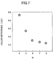
- a spectral characteristic of a toner image outputted from an electrophotographic image formation apparatus was estimated by using the spectral characteristic acquisition device 100 and simulation was executed that calculated a color difference that was an estimation error, from an estimated spectral characteristic.
- simulation obtained were a colorimetric result in a case where the number N of pixels of a spectral sensor that was had by the line sensor 107 was changed and a color difference ( ⁇ E) from a colorimetric result obtained from a higher-precision spectrometer.
- FIG. 7 is a diagram that illustrates a result of simulation. From a result as illustrated in FIG. 7 , it is possible to find that a color difference ( ⁇ E) is decreased as the number N of pixels of a spectral sensor is increased, so that a spectral characteristic is desired at a high precision.
- ⁇ E color difference
- a plurality of reference samples that are used for calculation of a transformation matrix G it is desirable for a plurality of reference samples that are used for calculation of a transformation matrix G to be homogenously selected from a reproducible color range (gamut) for a printed image in a color space of an XYZ color system, an L*a*b* color system, or the like.
- a transformation matrix G is used that is calculated based on thus selected reference sample, for example, it is possible to estimate a spectral characteristic of a printed image that is had by the measurement object 10, at high precision.
- toner images with 27 colors that are homogenously selected from a reproducible color range of an electrophotographic image formation apparatus are used as reference samples.
- FIG. 8 is a diagram that illustrates an XY chromaticity of each of reference samples with 27 colors, wherein each point indicates an XY chromaticity of a reference sample and a solid line indicates a reproducible color range of a toner image. As illustrated in FIG. 8 , it is possible to find that reference samples in the present embodiment are homogeneously selected from a reproducible color range of a toner image.
- a transformation matrix G that is calculated by using thus selected reference sample in the transformation matrix calculation part 113 is preliminarily stored in the transformation matrix storage part 119.
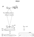
- the spectral characteristic acquisition device 100 is provided with a calibration unit 120 as a calibration color index that is used for calibration of a transformation matrix G calculated by using a reference sample, as illustrated in FIG. 9 .
- the transformation matrix calculation part 113 in the spectral characteristic acquisition device 100 has a function of calibrating a transformation matrix stored in the transformation matrix storage part 119 by using sensor data of the line sensor 107 that is obtained from a color index provided for the calibration unit 120, as a transformation matrix calibration means.
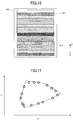
- the calibration unit 120 is such that strip-shaped color indices 120 that are long in an X-direction are aligned on a base material in an Y-direction as illustrated in FIG. 10 .
- each color index 121 is composed of 16 colors that are positioned on an outer periphery of a color range (gamut) reproducible on a printed image in an XY chromaticity distribution.
- a spectral characteristic of the color index 121 is preliminarily measured by using a high-precision spectrometer and a matrix R 1 that represents a spectral characteristic of the color index 121 is preliminarily stored in the reference data storage part 117.
- the calibration unit 120 it is preferable for the calibration unit 120 to be such that the color index 121 is provided as a replaceable one so that it is possible to change a target color intended to improve estimation precision of a spectral characteristic depending on the measurement object 10.
- a shape of the color index 121 is not limited to a strip shape but maybe a different shape.
- the calibration unit 120 may be a recording medium, such as a paper sheet, with a plurality of different color images that are printed in a predetermined area by an image formation apparatus such as an inkjet printer or a copying machine.
- the calibration unit 120 is mounted on a stage 122 as a conveyance means and conveyed between a light irradiation position that is irradiated with light from the line illumination light source 101 and the collimator lens 102 as a light irradiation means and a waiting position that is isolated from the light irradiation position.
- the stage 122 conveys the calibration unit 120 from a waiting position to a light irradiation position as calibration of a transformation matrix G is executed.
- a case 124 that surrounds the calibration unit 120 is provided at a waiting position of the calibration unit 120.
- the case 124 is such that internal temperature or humidity is kept to be a constant by a Peltier element, a desiccating agent, or the like.
- the calibration unit 120 is contained in the case 124 at a time of waiting thereof to be isolated from surrounding environment so that degradation of the color index 121 caused by influence of light, environmental temperature or humidity, or the like is suppressed.
- the calibration unit 120 together with the stage 122 are moved from a waiting position to a light irradiation position, the calibration unit 120 is irradiated with light from the line illumination light source 101, and the line sensor 107 receives light of a diffraction image to output an electric signal.
- the transformation matric calculation part 113 first acquires, from the reference data storage part 117, a matrix R ref that represents a preliminarily measured spectral characteristic of a reference sample and a matrix R 1 that represent a spectral characteristic of the color index 121 of the calibration unit 120, and adds the matrix R 1 to the matrix R ref to obtain a matrix R rev . Furthermore, a matrix V 1 of sensor data that are obtained from the color index 121 is added to a matrix V ref of sensor data that are obtained from a reference sample stored in the sensor data storage part 118, so that a matrix V rev is obtained.
- the transformation matrix calculation part 113 obtains a transformation matrix G 1 by using thus obtained matrices R rev and V rev and based on formula (6) and stores such a calibrated transformation matrix G 1 in the transformation matrix storage part 119. It is possible for the spectral characteristic calculation part 114 to estimate a spectral characteristic of the measurement object 10 at higher precision by using thus calibrated transformation matrix G 1 .
- results of estimation of a spectral characteristic of the measurement object 10 by using a pre-calibration transformation matrix G and a calibrated transformation matrix G 1 in the spectral characteristic acquisition device 100 will be described.
- Toner images with 125 colors were used as the measurement object 10 wherein each of colors C, M, and Y is combined at an image density of any one of 1, 25, 50, 75, and 100%.
- Precision of estimation of a spectral characteristic was evaluated based on results of estimation of a spectral characteristic that was executed by using two transformation matrices G and G 1 , and a color difference ( ⁇ E) from a spectral characteristic of an identical toner image that was measured by a spectrometer capable of a measurement at higher precision.
- FIG. 12 is a diagram that illustrates a spectral characteristic obtained by using a pre-calibration transformation matrix G in the spectral characteristic acquisition device 100 and a color difference ( ⁇ E) from a spectral characteristic measured by a spectrometer.
- FIG. 13 is a diagram that illustrates a spectral characteristic obtained by using a transformation matrix G 1 after calibration in the spectral characteristic acquisition device 100 and a color difference ( ⁇ E) from a spectral characteristic measured by a spectrometer.
- the spectral characteristic acquisition device 100 calibrates a transformation matrix that is used for estimation of a spectral characteristic, and thereby, it is possible to estimate a spectral characteristic of the measurement object 10 at higher precision.
- color indices 121 of the calibration unit 120 may be provided depending on a kind of or a purpose of measurement for the measurement object 10, or the like.
- a color index that has a color approximating a skin color may be provided for the calibration unit 120.
- the spectral characteristic calculation part 114 in the spectral characteristic acquisition device 100 may separately use a pre-calibration transformation matrix G and a post-calibration transformation matrix G 1 , depending on a position of measurement of the measurement object 10. For example, in a case where a color that is had by the measurement object 10 and a color coordinate thereof are known, a spectral characteristic is calculated by using a post-calibration transformation matrix G 1 at a position that has a particular color whereas a spectral characteristic is calculated by using a pre-calibration transformation matrix G at other positions.
- transformation matrices that are used for estimation of a spectral characteristic depending on a measurement position are separately used, and thereby, it is possible to estimate, at high precision, a spectral characteristic of an area that has a particular color, without degrading precision of estimation in other areas.
- a transformation matrix G may be calibrated by using the calibration unit 120 composed of different color indices 121 so that a plurality of transformation matrices G 2 , G 3 , ... are obtained and stored in the transformation matrix storage part 119. It is possible to estimate a spectral characteristic by using an optimum transformation matrix depending on a position of measurement of the measurement object 10 or the like, so that precision of estimation of such a spectral characteristic is further improved.
- a characteristic of the line illumination light source 101 may be changed by influence of a change of environment such as temperature, degradation with time, or the like, so as to change sensor data of the line sensor 107 even for an identical measurement object 10.
- the correction coefficient calculation part 115 in the spectral characteristic acquisition device 100 calculates a correction coefficient for sensor data by using a reference white part provided for the calibration unit 120.
- the spectral characteristic calculation part 114 estimates a spectral characteristic by using sensor data multiplied by a correction coefficient obtained by the correction coefficient calculation part 115, and thereby, it is possible to estimate a spectral characteristic at high precision constantly regardless of a change of the line illumination light source 101 or the like.
- the calibration unit 120 is provided with a reference white part to obtain a correction coefficient for sensor data.
- a reference white part is a white film, a white paper sheet for printing, or the like.
- reference sensor data V wref that are obtained from a reference white part is preliminarily measured and stored in the sensor data storage part 118 as a reference value.
- the spectral characteristic calculation part 114 produces a matrix V exp from sensor data v' corrected in accordance with formula (8) and estimates a spectral characteristic R exp of a measurement object by using a transformation matrix G 1 stored in the transformation matrix storage part 119 in accordance with formula (2).
- the correction coefficient calculation part 115 in the spectral characteristic acquisition device 100 calculates a correction coefficient for sensor data by using a reference white part provided for the calibration unit 120.
- the spectral characteristic calculation part 114 calculates a spectral characteristic of the measurement object 10 by using sensor data corrected by using a correction coefficient w, and thereby, it is possible to estimate such a spectral characteristic at high precision constantly regardless of an environmental change or the like.
- the spectral characteristic acquisition device 100 it is possible to calibrate a transformation matrix that is used for estimation of a spectral characteristic, depending on a characteristic of the measurement object 10 or the like, and it is possible to estimate a spectral characteristic of the measurement object 10 at higher precision. Furthermore, as sensor data that are outputted from the line sensor 107 are corrected, degradation of precision of estimation of a spectral characteristic that is caused by a change of the line illumination light source 101 or the like is suppressed so that it is possible to estimate a spectral characteristic at high precision constantly.
- the spectral characteristic acquisition device 100 as illustrated in FIG. 1 and FIG. 2 it is possible for the spectral characteristic acquisition device 100 as illustrated in FIG. 1 and FIG. 2 to provide a high speed operation due to the line sensor 107, so that it is possible to acquire spectral characteristic of the measurement object 10 at a high speed and at once, and it is possible to be applied to a field with a required high-speed measurement, such as an inline measurement for a printed image.
- the spectral characteristic acquisition device 100 according to the present embodiment to obtain a spectral characteristic of an entire surface of the measurement object 10 and it is possible to obtain a spectral characteristic of a recording medium with an arbitrary image printed thereon or the like, as well as a color chart with a predetermined color printed at a predetermined location thereof. Therefore, it is particularly effective in a case where a color is managed strictly and a control thereof or the like is executed.
- an image evaluation device 200 will be described that includes a spectral characteristic acquisition device 100.
- a component in a second embodiment that is identical to that of the embodiment described already will be provided with an identical numeral or letter to omit a description(s) thereof.
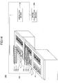
- FIG. 14 is a diagram that illustrates a general configuration of an image evaluation device 200 according to a second embodiment.
- the image evaluation device 200 has a spectral characteristic acquisition device 100 that includes a non-illustrated calibration unit 120, an image evaluation means 201, and a non-illustrated conveyance means that conveys a measurement object 10.
- the image evaluation device 200 evaluates an image formed on the measurement object 10 by an electrophotographic image formation apparatus or the like, over a full width thereof.
- FIG. 14 illustrates an example of the image evaluation device 200 that has one spectral characteristic acquisition device 100, for example, a plurality of spectral characteristic acquisition devices 100 may be arranged in parallel in a direction of a width of the measurement object 10.
- the image evaluation means 201 includes a CPU, a ROM, a main memory, and the like, wherein a program recorded in the ROM or the like is read out into the main memory and executed by the CPU and thereby each kind of function of the image evaluation means 201 is realized.
- a part or all of the image evaluation means 201 may only be realized by hardware.
- the image evaluation means 201 may physically be composed of a plurality of devices.
- the conveyance means conveys the measurement object 10 in a direction of an arrow in FIG. 14 .
- the conveyance means in the image evaluation device 200 is configured to convey the measurement object 10
- the image evaluation device 200 may be configured to move relative to the measurement object 10.
- a conveyance means for example, a conveyance roller, a conveyance belt, or the like is used. It is possible for the image evaluation means 201 to calculate spectral image data over an entire surface of an image formation portion of the measurement object 10 based on information of speed that is known or provided from an encoder sensor installed in a conveyance means.
- the image evaluation means 201 in the image evaluation device 200 is preferable for the image evaluation means 201 in the image evaluation device 200 to be capable of comparing a colorimetric result obtained by the line sensor 107 with a master image and sample and display a difference from such a master image. Thereby, it is possible for an operator to execute comparison with a master image simply.
- a master image may be configured in such a manner that it is possible to input a digital master image from exterior thereof, or a result of measurement of an arbitrary measurement object 10 that is measured by the image evaluation device 200 may be set as a master image.
- the image evaluation device 200 is configured by using the spectral characteristic acquisition device 100, and thereby, it is possible to realize the image evaluation device 200 capable of executing, at a high speed, evaluation of a color of an image formed on a conveyed measurement object or the like. Furthermore, it is possible for the image evaluation device 200 to execute image evaluation at high precision constantly, because it is possible for the spectral characteristic acquisition device 100 to appropriately calibrate a transformation matrix that is used for estimation of a spectral characteristic and obtain such a spectral characteristic at high precision.
- an image formation apparatus 300 will be described that includes an image evaluation device 200 according to the second embodiment.
- a component in a third embodiment that is identical to that of the embodiment described already will be provided with an identical numeral or letter to omit a description(s) thereof.
- FIG. 15 is a diagram that illustrates an image formation apparatus 300 according to a third embodiment.
- the image formation apparatus 300 has an image evaluation device 200, a paper feeding cassette 301a, a paper feeding cassette 301b, a paper feeding roller 302, a controller 303, a scanning optical system 304, a photoconductor body 305, an intermediate transfer body 306, a fixing roller 307, and a paper ejection roller 308.
- a measurement object 10 is a recording medium such as a paper sheet.
- the measurement object 10 is conveyed from the paper feeding cassette 301a or 301b and by a non-illustrated guide and the paper feeding roller 302. Simultaneously, the photoconductor body 305 is exposed to light by the scanning optical system 304 and an image provided and developed with a color material is transferred to the intermediate transfer body 306. An image transferred to the intermediate transfer body 306 is secondarily transferred to the measurement object 10 to be conveyed. An image transferred on the measurement object 10 is fixed by the fixing roller 307, and the measurement object 10 with an image formed on a surface thereof is ejected to an outside of such a machine by the paper ejection roller 308. Here, the image evaluation device 200 is placed in back of the fixing roller 307.
- the image formation apparatus 300 includes the image evaluation device 200, and thereby, it is possible to acquire information of a color of an image formed on the measurement object 10 in synchronization with conveyance of the measurement object 10. Furthermore, it is possible for the image evaluation device 200 to execute image evaluation at high precision based on a spectral characteristic that is estimated by using a transformation matrix that is calibrated appropriately.
- a control means controls an output of a light source in one scanning of a writing scanning optical system or controls an image formation condition such as a pre-printing gamma correction based on an acquired result of evaluation of an image color, and thereby, it is possible to reduce an irregularity of a color of an image formed on a recording medium that is the measurement object 10.
- a control means directly controls an amount of an ejected ink depending on a position of a head, and thereby, it is possible to reduce an irregularity of a color of an image formed on a recording medium.
- an image formation apparatus 400 will be described that includes an image evaluation device 200 according to the second embodiment.
- a component in a fourth embodiment that is identical to that of the embodiment described already will be provided with an identical numeral or letter to omit a description(s) thereof.
- FIG. 16 is a diagram that illustrates an image formation apparatus 400 according to a fourth embodiment.
- y, m, c, and k denote yellow, magenta, cyan, and black, respectively, wherein a letter of y, m, c, or k may be omitted for a description(s) in the following description.
- the image formation apparatus 400 is an electrophotographic tandem-type image formation apparatus and has a developing unit 60, an intermediate transfer belt 61, a transfer roller 55, a fixing device 56, and an image evaluation device 200.
- the developing unit 60 has a photoconductor drum 1, a light exposure control device 11, a cleaning device 51, an electrical charging device 52, a light exposure device 53, and a developing device 54.
- the photoconductor drum 1 rotates in a direction of an arrow A in the figure and a surface of the photoconductor drum 1 is electrically charged uniformly by the electrical charging device 52. Then, the light exposure device 53 scans a surface of the photoconductor drum 1 with laser light 7 in accordance with a signal from the light exposure control device 11 so that an electrostatic latent image is formed on such a surface of the photoconductor drum 1.
- An electrostatic latent image on a surface of the photoconductor drum 1 is provided with toner from the developing device 54 so as to provide a toner image.
- a developed toner image is transferred to the intermediate transfer belt 61.
- Developing units 60y, 60m, 60c, and 60k form yellow, magenta, cyan, and black toner images, respectively, and such toner images are superposed on and transferred to the intermediate transfer belt 61 so as to form a color toner image.
- a color toner image formed on the intermediate transfer belt 61 is transferred, by the transfer roller 55, to a recording medium that is supplied from a paper feeding stacker 57 and conveyed on a conveyance path 59.
- a recording medium with a color toner image transferred thereto is conveyed to and passes through the fixing device 56, and at that time, is heated and pressed so that such a toner image is fixed on a surface thereof.
- a recording medium with an image formed by an image formation process as described above is further conveyed, and is ejected onto a paper ejection stacker 142 after color information of such an image is acquired by the image evaluation device 200.
- an image formation condition is controlled based on a result of image evaluation of the image evaluation device 200, and thereby, it is possible to keep a quality of an image formed on a recording medium to be constant.
- the image formation apparatus 400 has a color index sample 123, a case 124 that stores the color index sample 123, a conveyance means 143 that conveys the color index sample 123, and a paper ejection bifurcation device 141.
- the color index sample 123 is one example of a calibration color index, and is a recording medium, such as a paper sheet, with a color index image printed on a surface thereof.
- the conveyance means 143 is configured to include a plurality of conveyance roller pairs or the like and conveys the color index sample 123.
- the image evaluation device 200 uses sensor data obtained from the color index sample 123 conveyed by the conveyance means 143 so as to calibrate a transformation matrix.
- the image formation apparatus 400 may have a plurality of color index samples 123 that have different color index images.
- the conveyance means 143 again conveys, to the case 124, the color index sample 123 conveyed from the case 124 and used for calibration of a transformation matrix in the image evaluation device 200.
- the paper ejection bifurcation device 141 ejects, onto the paper ejection stacker 142, a recording medium provided with an image formed by the developing unit 60 or the like and having passed through the fixing device 56, wherein an angle of a bifurcating claw is controlled in such a manner that the color index sample 123 used for calibration of a transformation matric in the image evaluation device 200 returns to the case 124.
- the color index sample 123 is conveyed to be interposed between a recording medium and a recording medium in such a manner that calibration of a transformation matrix in the image evaluation device 200 is executed at arbitrary timing. For example, calibration of a transformation matrix is executed in a case where the number of continuously measured recording media reaches 50, a case where a result of detection of a temperature sensor is changed by ⁇ 5 °C with respect to a reference value, or the like.
- execution thereof is caused in a case where a total number of measured ones reaches a constant value, a case where a monitored electric current value of a light source reaches a set amount of a change thereof, a case where maintenance or conveyance of the image formation apparatus 400 is executed, a case where a measurement is stopped urgently, a case where a light source is replaced, or the like.
- the image evaluation device 200 it is possible for the image evaluation device 200 to execute image evaluation at high precision based on a spectral characteristic that is estimated by using a transformation matrix that is calibrated appropriately. Therefore, the image formation apparatus 400 adjusts an image formation condition or the like based on a result of image evaluation in the image evaluation device 200, and thereby, it is possible to stably output an image at a high quality wherein color irregularity or the like is not caused even with time.
- FIG. 17 is a side view that illustrates a general configuration of a spectral characteristic acquisition device 500 according to a fifth embodiment.
- the spectral characteristic acquisition device 500 is provided with a calibration unit 510 as a calibration color index and a cover member 520 with a circularly hollow or cylindrical shape that covers the calibration unit 510 at a lower side of a supporting plate 501 that supports a measurement object 10 to be conveyed or mounted thereon (an opposite side of a line illumination light source 101).
- the supporting plate 501 is provided with an aperture in such a manner that it is possible to expose at least a portion of the calibration unit 510 to the line illumination light source 101 or the like.
- FIG. 18 is a diagram that illustrates a calibration unit 510 in the fifth embodiment.
- the calibration unit 510 is composed of a columnar member that is formed by applying a cutting operation to a metallic material such as aluminum, and a plurality of color indices 511 provided on an outer peripheral surface of such a columnar member.
- a color index 511 has a strip-like shape and is bonded to a planar portion at an outer periphery of a columnar member by a double-faced tape or the like.
- the calibration unit 510 is provided with a reference white part on an outer peripheral surface thereof, so that it is possible to correct sensor data by using such a reference white part.
- the calibration unit 510 is connected to a driving means, such as a motor, that is not illustrated in FIG. 17 , via a decelerating mechanism composed of a plurality of gears or the like, and provided rotatably in one direction or both directions centered at a rotation axis parallel to an X-direction.
- a driving means such as a motor
- a decelerating mechanism composed of a plurality of gears or the like
- the calibration unit 510 has a polygonal shape but may be of a different shape such as a circularly columnar shape.
- FIG. 19 is a diagram that illustrates a cover member 520 in the fifth embodiment.
- the cover member 520 is formed into a hollow or cylindrical shape by applying a cutting process, a pressing process, or the like to a metallic material such as aluminum, and a portion at an outer periphery thereof is provided with an aperture 521.
- a surface of the cover member 520 is blackened by an alumite process, coating, or the like, in order to suppress a measurement error caused by light reflection or the like.
- the cover member 520 is connected to a driving means such as a motor that is not illustrated in FIG. 17 via a decelerating mechanism composed of a plurality of gears or the like, and provided rotatably in one direction or both directions centered at a rotation axis parallel to an X-direction.
- a driving means such as a motor that is not illustrated in FIG. 17
- a decelerating mechanism composed of a plurality of gears or the like, and provided rotatably in one direction or both directions centered at a rotation axis parallel to an X-direction.
- the cover member 520 is provided in such a manner that the calibration unit 510 is contained in an interior thereof and thereby paper powder, dust, or the like, that is produced from a measurement object 10 such an a paper sheet is prevented from attaching to the calibration unit 510.
- the cover member 520 rotates in such a manner that the color index 511 of the calibration unit 510 is exposed to the line illumination light source 101 through the aperture 521 as illustrated in FIG. 17 .
- Calibration of a transformation matrix is executed based on sensor data of the plurality of color indices 511 that are acquired by rotating the calibration unit 510, or the like. Furthermore, calculation of a sensor data correction coefficient is executed based on sensor data of a reference white part that are acquired by rotating the calibration unit 510 so as to expose such a reference white part, or the like.
- the calibration unit 510 is rotated to acquire sensor data of the color indices 511 and such a reference white part, and thereby, it is also possible to execute calculation of sensor data correction coefficient simultaneously with calibration of a transformation matrix.
- the calibration unit 510 may be provided accessibly or detachably with respect to a light irradiation position for the line illumination light source 10 so as to move between a containment position for the cover member 520 and a spectral characteristic measurement position.
- a transformation matrix or calculation of sensor data correction coefficient from a result of measurement on a condition identical to that in a case where a spectral characteristic of the measurement object 10 is measured, and it is possible to reduce an influence of a light irradiation angle difference or a defocus and execute calibration of a transformation matrix or the like at higher precision.
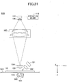
- the cover member 520 rotates in such a manner that the aperture 521 is positioned at a lower side thereof, and the calibration unit 510 is covered by the cover member 520 to be shielded from the line illumination light source 10, as illustrated in FIG. 21 .
- the cover member 520 it is preferable for the cover member 520 to be provided in such a manner that a top portion of an outer peripheral surface and a position of the measurement object 10 supported by the supporting plate 501 are positioned at an identical height in a Z-direction on a condition that the calibration unit 510 is covered. Due to such a configuration, deformation of the measurement object 10 mounted on the supporting plate 501, upward and downward flopping of the measurement object 10 conveyed on the supporting plate 501, or the like, is suppressed, and thereby, it is possible to obtain a spectral characteristic of the measurement object 10 at high precision.
- a cover member is not limited to a hollow or cylindrical shape as described above, and may be, for example, a flat-plate-shaped shutter 530 that opens or closes an aperture of the supporting plate 501, as illustrated in FIG. 22 .
- the shutter 530 is operated so as to open at a time of calibration of a transformation matrix, calculation of a correction coefficient, or the like, or close at a time of measurement of the measurement object 10 or non-operation of the spectral characteristic acquisition device 500, and thereby, attachment of paper powder, dust, or the like to the calibration unit 510 is prevented.
- the calibration unit 510 is covered by the cover member 520 that is provided movably, at a time of measurement of a spectral characteristic, non-operation of the spectral characteristic acquisition device 500, or the like, according to the fifth embodiment, and thereby, for example, attachment of paper powder, dust, or the like to the calibration unit 510 is prevented. Therefore, it is possible to execute calibration of a transformation matrix, calculation of a sensor data correction coefficient, or the like, at high precision constantly, and obtain a spectral characteristic of the measurement object 10 at high precision for a long period of time.
- the spectral characteristic acquisition device 500 may be mounted on an image evaluation device 200 according to the second embodiment. It is possible for the image evaluation device 200 with the spectral characteristic acquisition device 500 mounted thereon to execute calibration of a transformation matrix or calculation of a sensor data correction coefficient during the measurement object 10 is conveyed, and thereby, it is possible to obtain a spectral characteristic at higher precision. Furthermore, the image evaluation device 200 with the spectral characteristic acquisition device 500 mounted thereon may be installed in an image formation apparatus 300 or 400.
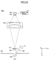
- FIG. 23 is a side view that illustrates a general configuration of a spectral characteristic acquisition device 600 according to a sixth embodiment.
- the spectral characteristic acquisition device 600 is such that a calibration unit 610 as a calibration color index is provided at a lower side of a supporting plate 501 that supports a measurement object 10 to be conveyed or mounted thereon (an opposite side of a line illumination light source 101).
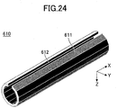
- FIG. 24 is a diagram that illustrates a calibration unit 610 in the sixth embodiment.
- the calibration unit 610 is composed of a hollow or cylindrical member that is formed by applying a cutting process, a pressing process, or the like, to a metallic material such as aluminum and has an aperture 612 at a part thereof, and a plurality of color indices 611 provided on an outer peripheral surface of such a hollow or cylindrical member.
- a color index 611 has a strip-like shape and is bonded to a planar portion at an outer periphery of such a hollow or cylindrical member by a double-faced tape or the like.
- the calibration unit 610 is provided with a reference white part on an outer peripheral surface thereof, and thereby, it is possible to correct sensor data by using such a reference white part.
- an inner peripheral surface of the calibration unit 610 is blackened by an alumite process, coating, or the like, so as to absorb light incident thereon.
- the calibration unit 610 is connected to a driving means such as a motor that is not illustrated in FIG. 23 via a decelerating mechanism calibrated by a plurality of gears or the like, and provided rotatably in one direction or both directions centered at a rotation axis parallel to an X-direction.
- a driving means such as a motor that is not illustrated in FIG. 23
- a decelerating mechanism calibrated by a plurality of gears or the like
- the calibration unit 610 has a polygonal hollow or cylindrical shape but may have a different shape such as a circularly cylindrical shape.
- the calibration unit 610 rotates in such a manner that the color indices 611 or a reference white part is irradiated with light, and thereby, calibration of a transformation matrix or calculation of a sensor data correction coefficient is executed based on sensor data obtained from the color indices 611 or such a reference white part.
- dark electric current of a line sensor 107 may be increased by a change in environmental temperature or the like in the spectral characteristic acquisition device 600 so as to cause a dispersion of a measurement result.
- Dark electric current is electric current flowing on a condition that no pixel of the liner senor 107 is irradiated with light, and for example, dark electric current is approximately doubled as temperature raises by 7 - 10 °C.
- a correction coefficient calculation part 115 in the spectral characteristic acquisition device 600 calculates a correction coefficient that corrects output data from the line sensor 107 so as to eliminate an influence of dark electric current.
- a spectral characteristic calculation part 114 estimates a spectral characteristic by using sensor data multiplied by a correction coefficient obtained by the correction coefficient calculation part 115, and thereby, it is possible to obtain a spectral characteristic at high precision constantly, independently of an increase or decrease in dark electric current or the like.
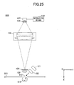
- the calibration unit 610 rotates in such a manner that light irradiating from a line illumination light source 101 is incident on the aperture 612 as illustrated in FIG. 25 .
- Light incident on the aperture 612 of the calibration unit 610 is absorbed by an interior of the calibration unit 610 so that no reflected light reaches the line sensor 107.
- the correction coefficient calculation part 115 acquires sensor data v d from the line sensor 107 on a condition that the aperture 612 of the calibration unit 610 is irradiated with light. Furthermore, the correction coefficient calculation part 115 acquires sensor data v w from the line sensor 107 on a condition that the calibration unit 610 rotates in such a manner that a reference white part is irradiated with light from the line illumination light source 101.
- Reference sensor data v wref obtained from a reference white part of the calibration unit 610 and reference sensor data v dref obtained from the aperture 612 of the calibration unit 610 at a time of measurement of v wref are stored in a sensor data storage part 118 as reference values.
- correction coefficient calculation part 115 acquires sensor data v d and v w
- the spectral characteristic calculation part 114 produces a matrix V exp from sensor data v' corrected in accordance with formula (10) and estimates a spectral characteristic R exp of a measurement object in accordance with formula (2) by using a transformation matrix G 1 stored in the transformation matrix storage part 119.
- a correction coefficient is calculated based on sensor data acquired from a reference white part and an aperture of the calibration unit 610 and sensor data acquired from the measurement object 10 are corrected thereby, so that it is possible to reduce a dispersion of an output from the line sensor 107 that is caused by an increase of decrease in dark electric current. Therefore, according to the sixth embodiment, it is possible to reduce a dispersion of an output from the line sensor 107 and thereby obtain a spectral characteristic of the measurement object 10 at higher precision for a long period of time.
- a cover member that covers a periphery of the calibration unit 610 or a flat-plate-shaped shutter that opens or closes an aperture of a supporting plate 501 may be provided.
- a cover member or a shutter is provided, and thereby, it is possible to prevent paper powder, dust, or the like, that is produced from the measurement object 10 such as a paper sheet, from attaching to the calibration unit 610.
- the spectral characteristic acquisition device 600 may be mounted in the image evaluation device 200 according to the second embodiment. It is possible for the image evaluation device 200 with the spectral characteristic acquisition device 600 mounted thereon to execute calibration of a transformation matrix or calculation of sensor data correction coefficient during the measurement object 10 is conveyed, and it is possible to obtain a spectral characteristic at higher precision. Furthermore, the image evaluation device 200 with the spectral characteristic acquisition device 600 mounted thereon may be installed in an image formation apparatus 300 or 400.
- the spectral characteristic acquisition device 100, 500, or 600 is not limited to an embodiment as described above and is capable of being installed in a variety of devices or apparatuses other than an image evaluation device and an image formation apparatus.
- the spectral characteristic acquisition device 100, 500, or 600 may be provided on a check device that checks reliability of a paper money, a credit card, or the like.
- At least one illustrative embodiment of the present invention may relate to at least one of a spectral characteristic acquisition device, an image evaluation device, and an image formation apparatus.
- At least one illustrative embodiment of the present invention may be provided while a description(s) provided above is/are taken into consideration, and may aim at providing a spectral characteristic acquisition device capable of calibrating a transformation matrix appropriately and estimating a spectral characteristic at high precision.
- a spectral characteristic acquisition device that has a light irradiation means that irradiates an object with light, a diffraction means that diffracts light reflected from the object to form a diffraction image, a light-receiving means that receives the diffraction image and outputs a signal depending on an amount of light in each different wavelength band, a spectral characteristic calculation means that estimates a spectral characteristic by using a preset transformation matrix and based on a signal output from the light-receiving means that is obtained from the object, a calibration color index that has a color with a known spectral characteristic, and a transformation matrix calibration means that calibrates the transformation matrix by using a signal output from the light-receiving means that is obtained from the calibration color index.
- Illustrative Embodiment (1) is a spectral characteristic acquisition device, characterized by having a light irradiation means that irradiates an object with light, a diffraction means that diffracts light reflected from the object to form a diffraction image, a light-receiving means that receives the diffraction image and outputs a signal depending on an amount of light in each different wavelength band, a spectral characteristic calculation means that estimates a spectral characteristic by using a preset transformation matrix and based on a signal output from the light-receiving means that is obtained from the object, a calibration color index that has a color with a known spectral characteristic, and a transformation matrix calibration means that calibrates the transformation matrix by using a signal output from the light-receiving means that is obtained from the calibration color index.
- Illustrative Embodiment (2) is the spectral characteristic acquisition device as described in Illustrative Embodiment (1), characterized in that the calibration color index has a reference white part, and by having a correction coefficient calculation means that calculates a correction coefficient for correcting a signal output from the light-receiving means that is obtained from the object based on a signal output from the light-receiving means that is obtained from the reference white part and a preset reference value.
- Illustrative Embodiment (3) is the spectral characteristic acquisition device as described in Illustrative Embodiment (1) or (2), characterized by having a conveyance means that conveys the calibration color index between a light irradiation position that is irradiated with light from the light irradiation means and a waiting position that is isolated from the light irradiation position.
- Illustrative Embodiment (4) is the spectral characteristic acquisition device as described in Illustrative Embodiment (3), characterized by having a case that surrounds the calibration color index at the waiting position.
- Illustrative Embodiment (5) is the spectral characteristic acquisition device as described in Illustrative Embodiment (1) or (2), characterized in that the calibration color index has a columnar shape and is provided rotatably at a light irradiation position that is irradiated with light from the light irradiation means.
- Illustrative Embodiment (6) is the spectral characteristic acquisition device as described in Illustrative Embodiment (5), characterized in that the calibration color index is provided accessibly or detachably to the light irradiation position.
- Illustrative Embodiment (7) is the spectral characteristic acquisition device as described in Illustrative Embodiment (5) or (6), characterized by having a cover member that is provided movably in such a manner that the calibration color index is exposed to or shielded from the light irradiation means.
- Illustrative Embodiment (8) is the spectral characteristic acquisition device as described in Illustrative Embodiment (1), characterized in that the calibration color index has a reference white part and a hollow or cylindrical shape provided with an aperture and is provided rotatably at a light irradiation position that is irradiated with light from the light irradiation means, and by having a correction coefficient calculation means that calculates a correction coefficient for correcting a signal output from the light-receiving means that is obtained from the object, based on a signal output from the light-receiving means that is acquired from each of the reference white part and the aperture of the calibration color index and a preset reference value.
- Illustrative Embodiment (9) is an image evaluation device, characterized by having the spectral characteristic acquisition device as described in any one of Illustrative Embodiments (1) to (8), and an image evaluation means that evaluates an image formed on the object based on a spectral characteristic obtained by the spectral characteristic acquisition device.
- Illustrative Embodiment (10) is an image formation apparatus, characterized by having the image evaluation device as described in Illustrative Embodiment (9).
- a spectral characteristic acquisition device capable of calibrating a transformation matrix appropriately and estimating a spectral characteristic at high precision.
Landscapes
- Physics & Mathematics (AREA)
- Spectroscopy & Molecular Physics (AREA)
- General Physics & Mathematics (AREA)
- Engineering & Computer Science (AREA)
- Theoretical Computer Science (AREA)
- Chemical & Material Sciences (AREA)
- Biochemistry (AREA)
- Signal Processing (AREA)
- Health & Medical Sciences (AREA)
- Life Sciences & Earth Sciences (AREA)
- Multimedia (AREA)
- Analytical Chemistry (AREA)
- Pathology (AREA)
- General Health & Medical Sciences (AREA)
- Immunology (AREA)
- Mathematical Physics (AREA)
- General Engineering & Computer Science (AREA)
- Spectrometry And Color Measurement (AREA)
- Accessory Devices And Overall Control Thereof (AREA)
- Investigating Or Analysing Materials By Optical Means (AREA)
Claims (4)
- Dispositif d'acquisition de caractéristique spectrale, comprenant :une partie d'irradiation de lumière comprenant une source de lumière d'éclairage linéaire (101) configurée pour irradier un objet avec de la lumière ;une partie de diffraction configurée pour diffracter de la lumière réfléchie à partir de l'objet pour fournir de la lumière diffractée ;une partie de réception de lumière configurée pour recevoir la lumière diffractée et produire en sortie un signal sur la base d'une quantité de la lumière diffractée ;une unité de calibrage (510), en tant qu'indice de couleur de calibrage (511), configurée pour inclure une pluralité de couleurs avec des caractéristiques spectrales connues et pour inclure une partie blanche de référence ; etune partie d'opération configurée pour calculer une caractéristique spectrale de l'objet à partir d'un signal produit en sortie à partir de la partie de réception de lumière en utilisant une matrice de transformation prédéterminée, pour calibrer la matrice de transformation en utilisant l'indice de couleur de calibrage, et pour corriger un signal produit en sortie à partir de la partie de réception de lumière n utilisant la partie blanche de référence,caractérisé en ce quel'unité de calibrage (510) inclut un élément en colonne,dans lequel l'indice de couleur de calibrage (511) est prévu sur une surface périphérique extérieure de l'élément en colonne, eten ce que l'unité de calibrage (510) est rotative et couverte avec un élément couvercle rotatif (520) d'une forme cylindrique avec une ouverture (521), dans lequel l'ouverture (521) est configurée de telle sorte qu'il soit possible d'exposer au moins une portion de l'unité de calibrage (501) à la source de lumière d'éclairage linéaire (101) lorsque l'élément couvercle (520) effectue une rotation, et la partie d'opération est en outre configurée pour corriger un signal produit en sortie à partir de la partie de réception de lumière en utilisant l'ouverture, dans lequel la surface cylindrique de l'élément couvercle rotatif couvre l'unité de calibrage (510) sur un côté inférieur d'une plaque de support (501) qui supporte un objet de mesure destiné à être transporté ou monté sur celle-ci, ladite plaque de support étant pourvue d'une ouverture de manière telle qu'il soit possible d'exposer au moins une portion de l'unité de calibrage (510) à la source de lumière d'éclairage linéaire (101).
- Dispositif d'acquisition de caractéristique spectrale selon la revendication 1, comprenant en outre :
une partie de mouvement configurée pour déplacer l'indice de couleur de calibrage. - Dispositif d'évaluation d'image, comprenant :le dispositif d'acquisition de caractéristique spectrale selon l'une quelconque des revendications 1 à 4 ; etune partir d'évaluation d'image configurée pour évaluer une image formée sur l'objet sur la base d'une caractéristique spectrale de l'objet acquise par le dispositif d'acquisition de caractéristique spectrale.
- Appareil de formation d'image, comprenant :un dispositif de formation d'image configuré pour former une image sur l'objet ; etle dispositif d'évaluation d'image selon la revendication 5.
Applications Claiming Priority (3)
| Application Number | Priority Date | Filing Date | Title |
|---|---|---|---|
| JP2014030270 | 2014-02-20 | ||
| JP2014099572 | 2014-05-13 | ||
| JP2014255400A JP6550743B2 (ja) | 2014-02-20 | 2014-12-17 | 分光特性取得装置、画像評価装置及び画像形成装置 |
Publications (2)
| Publication Number | Publication Date |
|---|---|
| EP2916116A1 EP2916116A1 (fr) | 2015-09-09 |
| EP2916116B1 true EP2916116B1 (fr) | 2020-05-20 |
Family
ID=52465284
Family Applications (1)
| Application Number | Title | Priority Date | Filing Date |
|---|---|---|---|
| EP15154809.6A Active EP2916116B1 (fr) | 2014-02-20 | 2015-02-12 | Dispositif d'acquisition de caractéristique spectrale, dispositif d'évaluation d'image, et appareil de formation d'image |
Country Status (3)
| Country | Link |
|---|---|
| US (1) | US9224080B2 (fr) |
| EP (1) | EP2916116B1 (fr) |
| JP (1) | JP6550743B2 (fr) |
Families Citing this family (12)
| Publication number | Priority date | Publication date | Assignee | Title |
|---|---|---|---|---|
| EP2701377A3 (fr) * | 2012-04-27 | 2014-12-10 | Esko Software Bvba | Calcul des caractéristiques spectrales de la couleur résultant de la superposition de colorants |
| JP5990093B2 (ja) * | 2012-11-29 | 2016-09-07 | キヤノン株式会社 | 画像処理装置、画像処理方法ならびにプログラム |
| JP6308156B2 (ja) * | 2015-03-25 | 2018-04-11 | 京セラドキュメントソリューションズ株式会社 | 画像読取装置、画像形成装置 |
| WO2018021048A1 (fr) * | 2016-07-27 | 2018-02-01 | 凸版印刷株式会社 | Dispositif d'étalonnage de couleurs, système d'étalonnage de couleurs, hologramme d'étalonnage de couleurs, procédé d'étalonnage de couleurs, et programme |
| DE102017220361B4 (de) * | 2016-12-14 | 2023-04-20 | Heidelberger Druckmaschinen Ag | Verfahren und Testmuster zur Detektion und Kompensation ausgefallener Druckdüsen in einer Inkjet-Druckmaschine |
| JP6984400B2 (ja) * | 2017-12-26 | 2021-12-22 | セイコーエプソン株式会社 | 分光測定装置、電子機器及び分光測定方法 |
| JP6988512B2 (ja) | 2018-01-24 | 2022-01-05 | 株式会社リコー | 分光特性取得装置、画像形成装置、画像形成システム |
| JP7095304B2 (ja) | 2018-02-15 | 2022-07-05 | 株式会社リコー | 分光特性取得装置、画像形成装置、画像形成システム、画像形成装置の管理システム、及び画像形成装置の管理方法 |
| JP7024624B2 (ja) * | 2018-06-25 | 2022-02-24 | 株式会社リコー | 支持枠、分光器、分光分析ユニット、及び画像形成装置 |
| JP7087735B2 (ja) * | 2018-06-29 | 2022-06-21 | 株式会社リコー | 分光特性取得装置、画像形成装置、及び画像形成装置の管理システム |
| JP2021025803A (ja) * | 2019-07-31 | 2021-02-22 | 株式会社リコー | 分光センサの校正装置、及び分光センサの校正方法 |
| CN115438515B (zh) * | 2022-11-07 | 2023-01-24 | 中国人民解放军国防科技大学 | 大厚度透明基底镀制金属薄膜的仿真与计算相结合的方法 |
Citations (3)
| Publication number | Priority date | Publication date | Assignee | Title |
|---|---|---|---|---|
| JP2002290685A (ja) * | 2001-03-26 | 2002-10-04 | Sharp Corp | 画像読み取り装置及び入力素子の補正方法 |
| JP2010114498A (ja) * | 2008-11-04 | 2010-05-20 | Fuji Xerox Co Ltd | 画像形成装置および画像読取装置 |
| US20120070200A1 (en) * | 2010-09-21 | 2012-03-22 | Fuji Xerox Co., Ltd. | Image scanner, image forming apparatus and image adjusting method of image scanner |
Family Cites Families (22)
| Publication number | Priority date | Publication date | Assignee | Title |
|---|---|---|---|---|
| JPS59163967A (ja) * | 1983-03-08 | 1984-09-17 | Canon Inc | 像再生装置 |
| JPH0620222B2 (ja) | 1987-07-30 | 1994-03-16 | 大日本スクリ−ン製造株式会社 | 画像走査読取り装置の受光部の感度基準設定方法 |
| JP3566334B2 (ja) | 1994-03-25 | 2004-09-15 | キヤノン株式会社 | 画像処理装置およびその方法 |
| US6832824B1 (en) * | 1998-10-30 | 2004-12-21 | Hewlett-Packard Development Company, L.P. | Color-calibration sensor system for incremental printing |
| JP2002310799A (ja) | 2001-04-16 | 2002-10-23 | Dac Engineering Kk | 印刷物のカラーインキ濃度検出方法およびカラーインキ濃度検出装置 |
| JP3925301B2 (ja) | 2001-07-12 | 2007-06-06 | コニカミノルタセンシング株式会社 | 分光特性測定装置および同装置の分光感度の波長シフト補正方法 |
| JP2003139702A (ja) | 2001-10-31 | 2003-05-14 | Web Tec Kk | 印刷シ−ト上の多色刷り画像濃度検出装置 |
| EP1528380A4 (fr) * | 2002-07-26 | 2009-12-09 | Olympus Corp | Systeme de traitement d'images |
| US6975949B2 (en) | 2004-04-27 | 2005-12-13 | Xerox Corporation | Full width array scanning spectrophotometer |
| WO2006045620A1 (fr) | 2004-10-28 | 2006-05-04 | Gretagmacbeth Ag | Procede de correction de valeurs mesurees d'images |
| JP2008304205A (ja) | 2007-06-05 | 2008-12-18 | Olympus Corp | 分光特性推定装置および分光特性推定プログラム |
| JP5440110B2 (ja) | 2009-03-30 | 2014-03-12 | 株式会社リコー | 分光特性取得装置、分光特性取得方法、画像評価装置、及び画像形成装置 |
| JP5655437B2 (ja) | 2009-09-14 | 2015-01-21 | 株式会社リコー | 分光特性取得装置 |
| JP2012145823A (ja) | 2011-01-13 | 2012-08-02 | Ricoh Co Ltd | 光走査装置及び画像形成装置 |
| JP2012154711A (ja) | 2011-01-25 | 2012-08-16 | Jvc Kenwood Corp | 分光スペクトル推定装置および学習スペクトル生成方法 |
| JP5717052B2 (ja) | 2011-04-25 | 2015-05-13 | 株式会社リコー | 分光計測装置、画像評価装置、及び画像形成装置 |
| JP5884347B2 (ja) * | 2011-09-12 | 2016-03-15 | 株式会社リコー | 分光特性取得装置及び分光特性取得方法、画像評価装置、並びに画像形成装置 |
| JP5880053B2 (ja) | 2012-01-12 | 2016-03-08 | 株式会社リコー | 分光特性取得装置及び画像形成装置 |
| JP6051543B2 (ja) | 2012-03-09 | 2016-12-27 | 株式会社リコー | 分光計測装置、画像評価装置及び画像形成装置 |
| JP5910989B2 (ja) | 2012-03-09 | 2016-04-27 | 株式会社リコー | 分光計測装置、画像評価装置及び画像形成装置 |
| JP6311267B2 (ja) | 2013-05-10 | 2018-04-18 | 株式会社リコー | 分光特性取得装置、画像評価装置、画像形成装置 |
| JP6232831B2 (ja) * | 2013-08-15 | 2017-11-22 | 株式会社リコー | 分光特性取得装置、画像評価装置及び画像形成装置 |
-
2014
- 2014-12-17 JP JP2014255400A patent/JP6550743B2/ja active Active
-
2015
- 2015-02-05 US US14/614,497 patent/US9224080B2/en not_active Expired - Fee Related
- 2015-02-12 EP EP15154809.6A patent/EP2916116B1/fr active Active
Patent Citations (3)
| Publication number | Priority date | Publication date | Assignee | Title |
|---|---|---|---|---|
| JP2002290685A (ja) * | 2001-03-26 | 2002-10-04 | Sharp Corp | 画像読み取り装置及び入力素子の補正方法 |
| JP2010114498A (ja) * | 2008-11-04 | 2010-05-20 | Fuji Xerox Co Ltd | 画像形成装置および画像読取装置 |
| US20120070200A1 (en) * | 2010-09-21 | 2012-03-22 | Fuji Xerox Co., Ltd. | Image scanner, image forming apparatus and image adjusting method of image scanner |
Also Published As
| Publication number | Publication date |
|---|---|
| JP2015232540A (ja) | 2015-12-24 |
| JP6550743B2 (ja) | 2019-07-31 |
| US20150235114A1 (en) | 2015-08-20 |
| EP2916116A1 (fr) | 2015-09-09 |
| US9224080B2 (en) | 2015-12-29 |
Similar Documents
| Publication | Publication Date | Title |
|---|---|---|
| EP2916116B1 (fr) | Dispositif d'acquisition de caractéristique spectrale, dispositif d'évaluation d'image, et appareil de formation d'image | |
| US8879057B2 (en) | Spectral characteristic acquiring apparatus, spectral characteristic acquiring method and image evaluating apparatus | |
| EP3527968B1 (fr) | Appareil d'acquisition de caractéristique spectrale, appareil de formation d'images, système de formation d'images, système de gestion d'appareil de formation d'images et procédé de gestion d'appareil de formation d'images | |
| JP7087735B2 (ja) | 分光特性取得装置、画像形成装置、及び画像形成装置の管理システム | |
| JP6988512B2 (ja) | 分光特性取得装置、画像形成装置、画像形成システム | |
| US20130235376A1 (en) | Spectrometer, and image evaluating unit and image forming device incorporating the same | |
| JP5834938B2 (ja) | 分光特性取得装置、画像評価装置、画像形成装置及び分光特性取得方法 | |
| US20130235249A1 (en) | Spectrometer, and image evaluating unit and image forming device incorporating the same | |
| JP2002365139A (ja) | 角度、方位角および変位に敏感でないカラープリンタ用色修正システム及び分光光度計 | |
| JP6232831B2 (ja) | 分光特性取得装置、画像評価装置及び画像形成装置 | |
| JP2010261861A (ja) | 分光特性取得装置、画像評価装置、及び画像形成装置 | |
| JP2010210456A (ja) | 光学特性測定装置、分光測色装置及び画像形成装置 | |
| JP5402740B2 (ja) | 分光特性取得装置、画像評価装置及び画像形成装置 | |
| JP2013061175A (ja) | 分光特性取得装置及び分光特性取得方法、画像評価装置、並びに画像形成装置 | |
| JP2017106887A (ja) | 分光計測ユニット、分光計測装置、画像形成装置及び分光計測方法 | |
| JP5644296B2 (ja) | 分光特性取得装置、画像評価装置、及び画像形成装置 | |
| JP2014048271A (ja) | 演算装置及び演算方法、分光反射率取得装置、画像評価装置、並びに画像形成装置 | |
| JP5493364B2 (ja) | 画像濃度計測方法及び画像濃度計測装置並びに画像形成装置 | |
| JP6669383B2 (ja) | 測定装置、画像形成装置及び画像測定装置 | |
| JP2021021704A (ja) | 分光素子、分光計測装置、画像評価装置および画像形成装置 | |
| JP2016008897A (ja) | 画像特性計測装置、画像評価装置、画像形成装置 | |
| JP2009222966A (ja) | 画像濃度計測方法、画像濃度計測装置、画像形成装置および画像補正方法 | |
| JP2015036659A (ja) | 分光特性取得装置、画像評価装置及び画像形成装置 |
Legal Events
| Date | Code | Title | Description |
|---|---|---|---|
| PUAI | Public reference made under article 153(3) epc to a published international application that has entered the european phase |
Free format text: ORIGINAL CODE: 0009012 |
|
| 17P | Request for examination filed |
Effective date: 20150212 |
|
| AK | Designated contracting states |
Kind code of ref document: A1 Designated state(s): AL AT BE BG CH CY CZ DE DK EE ES FI FR GB GR HR HU IE IS IT LI LT LU LV MC MK MT NL NO PL PT RO RS SE SI SK SM TR |
|
| AX | Request for extension of the european patent |
Extension state: BA ME |
|
| STAA | Information on the status of an ep patent application or granted ep patent |
Free format text: STATUS: EXAMINATION IS IN PROGRESS |
|
| 17Q | First examination report despatched |
Effective date: 20190624 |
|
| GRAP | Despatch of communication of intention to grant a patent |
Free format text: ORIGINAL CODE: EPIDOSNIGR1 |
|
| STAA | Information on the status of an ep patent application or granted ep patent |
Free format text: STATUS: GRANT OF PATENT IS INTENDED |
|
| INTG | Intention to grant announced |
Effective date: 20191209 |
|
| GRAS | Grant fee paid |
Free format text: ORIGINAL CODE: EPIDOSNIGR3 |
|
| GRAA | (expected) grant |
Free format text: ORIGINAL CODE: 0009210 |
|
| STAA | Information on the status of an ep patent application or granted ep patent |
Free format text: STATUS: THE PATENT HAS BEEN GRANTED |
|
| AK | Designated contracting states |
Kind code of ref document: B1 Designated state(s): AL AT BE BG CH CY CZ DE DK EE ES FI FR GB GR HR HU IE IS IT LI LT LU LV MC MK MT NL NO PL PT RO RS SE SI SK SM TR |
|
| REG | Reference to a national code |
Ref country code: GB Ref legal event code: FG4D |
|
| REG | Reference to a national code |
Ref country code: CH Ref legal event code: EP |
|
| REG | Reference to a national code |
Ref country code: DE Ref legal event code: R096 Ref document number: 602015052968 Country of ref document: DE |
|
| REG | Reference to a national code |
Ref country code: AT Ref legal event code: REF Ref document number: 1272900 Country of ref document: AT Kind code of ref document: T Effective date: 20200615 |
|
| REG | Reference to a national code |
Ref country code: LT Ref legal event code: MG4D |
|
| REG | Reference to a national code |
Ref country code: NL Ref legal event code: MP Effective date: 20200520 |
|
| PG25 | Lapsed in a contracting state [announced via postgrant information from national office to epo] |
Ref country code: PT Free format text: LAPSE BECAUSE OF FAILURE TO SUBMIT A TRANSLATION OF THE DESCRIPTION OR TO PAY THE FEE WITHIN THE PRESCRIBED TIME-LIMIT Effective date: 20200921 Ref country code: FI Free format text: LAPSE BECAUSE OF FAILURE TO SUBMIT A TRANSLATION OF THE DESCRIPTION OR TO PAY THE FEE WITHIN THE PRESCRIBED TIME-LIMIT Effective date: 20200520 Ref country code: LT Free format text: LAPSE BECAUSE OF FAILURE TO SUBMIT A TRANSLATION OF THE DESCRIPTION OR TO PAY THE FEE WITHIN THE PRESCRIBED TIME-LIMIT Effective date: 20200520 Ref country code: GR Free format text: LAPSE BECAUSE OF FAILURE TO SUBMIT A TRANSLATION OF THE DESCRIPTION OR TO PAY THE FEE WITHIN THE PRESCRIBED TIME-LIMIT Effective date: 20200821 Ref country code: NO Free format text: LAPSE BECAUSE OF FAILURE TO SUBMIT A TRANSLATION OF THE DESCRIPTION OR TO PAY THE FEE WITHIN THE PRESCRIBED TIME-LIMIT Effective date: 20200820 Ref country code: IS Free format text: LAPSE BECAUSE OF FAILURE TO SUBMIT A TRANSLATION OF THE DESCRIPTION OR TO PAY THE FEE WITHIN THE PRESCRIBED TIME-LIMIT Effective date: 20200920 Ref country code: SE Free format text: LAPSE BECAUSE OF FAILURE TO SUBMIT A TRANSLATION OF THE DESCRIPTION OR TO PAY THE FEE WITHIN THE PRESCRIBED TIME-LIMIT Effective date: 20200520 |
|
| PG25 | Lapsed in a contracting state [announced via postgrant information from national office to epo] |
Ref country code: BG Free format text: LAPSE BECAUSE OF FAILURE TO SUBMIT A TRANSLATION OF THE DESCRIPTION OR TO PAY THE FEE WITHIN THE PRESCRIBED TIME-LIMIT Effective date: 20200820 Ref country code: LV Free format text: LAPSE BECAUSE OF FAILURE TO SUBMIT A TRANSLATION OF THE DESCRIPTION OR TO PAY THE FEE WITHIN THE PRESCRIBED TIME-LIMIT Effective date: 20200520 Ref country code: RS Free format text: LAPSE BECAUSE OF FAILURE TO SUBMIT A TRANSLATION OF THE DESCRIPTION OR TO PAY THE FEE WITHIN THE PRESCRIBED TIME-LIMIT Effective date: 20200520 Ref country code: HR Free format text: LAPSE BECAUSE OF FAILURE TO SUBMIT A TRANSLATION OF THE DESCRIPTION OR TO PAY THE FEE WITHIN THE PRESCRIBED TIME-LIMIT Effective date: 20200520 |
|
| REG | Reference to a national code |
Ref country code: AT Ref legal event code: MK05 Ref document number: 1272900 Country of ref document: AT Kind code of ref document: T Effective date: 20200520 |
|
| PG25 | Lapsed in a contracting state [announced via postgrant information from national office to epo] |
Ref country code: NL Free format text: LAPSE BECAUSE OF FAILURE TO SUBMIT A TRANSLATION OF THE DESCRIPTION OR TO PAY THE FEE WITHIN THE PRESCRIBED TIME-LIMIT Effective date: 20200520 Ref country code: AL Free format text: LAPSE BECAUSE OF FAILURE TO SUBMIT A TRANSLATION OF THE DESCRIPTION OR TO PAY THE FEE WITHIN THE PRESCRIBED TIME-LIMIT Effective date: 20200520 |
|
| PG25 | Lapsed in a contracting state [announced via postgrant information from national office to epo] |
Ref country code: AT Free format text: LAPSE BECAUSE OF FAILURE TO SUBMIT A TRANSLATION OF THE DESCRIPTION OR TO PAY THE FEE WITHIN THE PRESCRIBED TIME-LIMIT Effective date: 20200520 Ref country code: RO Free format text: LAPSE BECAUSE OF FAILURE TO SUBMIT A TRANSLATION OF THE DESCRIPTION OR TO PAY THE FEE WITHIN THE PRESCRIBED TIME-LIMIT Effective date: 20200520 Ref country code: IT Free format text: LAPSE BECAUSE OF FAILURE TO SUBMIT A TRANSLATION OF THE DESCRIPTION OR TO PAY THE FEE WITHIN THE PRESCRIBED TIME-LIMIT Effective date: 20200520 Ref country code: ES Free format text: LAPSE BECAUSE OF FAILURE TO SUBMIT A TRANSLATION OF THE DESCRIPTION OR TO PAY THE FEE WITHIN THE PRESCRIBED TIME-LIMIT Effective date: 20200520 Ref country code: CZ Free format text: LAPSE BECAUSE OF FAILURE TO SUBMIT A TRANSLATION OF THE DESCRIPTION OR TO PAY THE FEE WITHIN THE PRESCRIBED TIME-LIMIT Effective date: 20200520 Ref country code: DK Free format text: LAPSE BECAUSE OF FAILURE TO SUBMIT A TRANSLATION OF THE DESCRIPTION OR TO PAY THE FEE WITHIN THE PRESCRIBED TIME-LIMIT Effective date: 20200520 Ref country code: SM Free format text: LAPSE BECAUSE OF FAILURE TO SUBMIT A TRANSLATION OF THE DESCRIPTION OR TO PAY THE FEE WITHIN THE PRESCRIBED TIME-LIMIT Effective date: 20200520 Ref country code: EE Free format text: LAPSE BECAUSE OF FAILURE TO SUBMIT A TRANSLATION OF THE DESCRIPTION OR TO PAY THE FEE WITHIN THE PRESCRIBED TIME-LIMIT Effective date: 20200520 |
|
| REG | Reference to a national code |
Ref country code: DE Ref legal event code: R097 Ref document number: 602015052968 Country of ref document: DE |
|
| PG25 | Lapsed in a contracting state [announced via postgrant information from national office to epo] |
Ref country code: SK Free format text: LAPSE BECAUSE OF FAILURE TO SUBMIT A TRANSLATION OF THE DESCRIPTION OR TO PAY THE FEE WITHIN THE PRESCRIBED TIME-LIMIT Effective date: 20200520 Ref country code: PL Free format text: LAPSE BECAUSE OF FAILURE TO SUBMIT A TRANSLATION OF THE DESCRIPTION OR TO PAY THE FEE WITHIN THE PRESCRIBED TIME-LIMIT Effective date: 20200520 |
|
| PLBE | No opposition filed within time limit |
Free format text: ORIGINAL CODE: 0009261 |
|
| STAA | Information on the status of an ep patent application or granted ep patent |
Free format text: STATUS: NO OPPOSITION FILED WITHIN TIME LIMIT |
|
| 26N | No opposition filed |
Effective date: 20210223 |
|
| PG25 | Lapsed in a contracting state [announced via postgrant information from national office to epo] |
Ref country code: SI Free format text: LAPSE BECAUSE OF FAILURE TO SUBMIT A TRANSLATION OF THE DESCRIPTION OR TO PAY THE FEE WITHIN THE PRESCRIBED TIME-LIMIT Effective date: 20200520 |
|
| PG25 | Lapsed in a contracting state [announced via postgrant information from national office to epo] |
Ref country code: MC Free format text: LAPSE BECAUSE OF FAILURE TO SUBMIT A TRANSLATION OF THE DESCRIPTION OR TO PAY THE FEE WITHIN THE PRESCRIBED TIME-LIMIT Effective date: 20200520 |
|
| REG | Reference to a national code |
Ref country code: BE Ref legal event code: MM Effective date: 20210228 |
|
| PG25 | Lapsed in a contracting state [announced via postgrant information from national office to epo] |
Ref country code: CH Free format text: LAPSE BECAUSE OF NON-PAYMENT OF DUE FEES Effective date: 20210228 Ref country code: LU Free format text: LAPSE BECAUSE OF NON-PAYMENT OF DUE FEES Effective date: 20210212 Ref country code: LI Free format text: LAPSE BECAUSE OF NON-PAYMENT OF DUE FEES Effective date: 20210228 |
|
| PG25 | Lapsed in a contracting state [announced via postgrant information from national office to epo] |
Ref country code: IE Free format text: LAPSE BECAUSE OF NON-PAYMENT OF DUE FEES Effective date: 20210212 |
|
| PG25 | Lapsed in a contracting state [announced via postgrant information from national office to epo] |
Ref country code: BE Free format text: LAPSE BECAUSE OF NON-PAYMENT OF DUE FEES Effective date: 20210228 |
|
| PG25 | Lapsed in a contracting state [announced via postgrant information from national office to epo] |
Ref country code: HU Free format text: LAPSE BECAUSE OF FAILURE TO SUBMIT A TRANSLATION OF THE DESCRIPTION OR TO PAY THE FEE WITHIN THE PRESCRIBED TIME-LIMIT; INVALID AB INITIO Effective date: 20150212 |
|
| P01 | Opt-out of the competence of the unified patent court (upc) registered |
Effective date: 20230522 |
|
| PG25 | Lapsed in a contracting state [announced via postgrant information from national office to epo] |
Ref country code: CY Free format text: LAPSE BECAUSE OF FAILURE TO SUBMIT A TRANSLATION OF THE DESCRIPTION OR TO PAY THE FEE WITHIN THE PRESCRIBED TIME-LIMIT Effective date: 20200520 |
|
| PG25 | Lapsed in a contracting state [announced via postgrant information from national office to epo] |
Ref country code: MK Free format text: LAPSE BECAUSE OF FAILURE TO SUBMIT A TRANSLATION OF THE DESCRIPTION OR TO PAY THE FEE WITHIN THE PRESCRIBED TIME-LIMIT Effective date: 20200520 |
|
| PG25 | Lapsed in a contracting state [announced via postgrant information from national office to epo] |
Ref country code: MT Free format text: LAPSE BECAUSE OF FAILURE TO SUBMIT A TRANSLATION OF THE DESCRIPTION OR TO PAY THE FEE WITHIN THE PRESCRIBED TIME-LIMIT Effective date: 20200520 |
|
| PG25 | Lapsed in a contracting state [announced via postgrant information from national office to epo] |
Ref country code: TR Free format text: LAPSE BECAUSE OF FAILURE TO SUBMIT A TRANSLATION OF THE DESCRIPTION OR TO PAY THE FEE WITHIN THE PRESCRIBED TIME-LIMIT Effective date: 20200520 |
|
| PGFP | Annual fee paid to national office [announced via postgrant information from national office to epo] |
Ref country code: GB Payment date: 20260219 Year of fee payment: 12 |
|
| PGFP | Annual fee paid to national office [announced via postgrant information from national office to epo] |
Ref country code: DE Payment date: 20260218 Year of fee payment: 12 |
|
| PGFP | Annual fee paid to national office [announced via postgrant information from national office to epo] |
Ref country code: FR Payment date: 20260218 Year of fee payment: 12 |