EP2916126B1 - Outil analytique de détection d'état d'alimentation d'échantillon - Google Patents
Outil analytique de détection d'état d'alimentation d'échantillon Download PDFInfo
- Publication number
- EP2916126B1 EP2916126B1 EP15163425.0A EP15163425A EP2916126B1 EP 2916126 B1 EP2916126 B1 EP 2916126B1 EP 15163425 A EP15163425 A EP 15163425A EP 2916126 B1 EP2916126 B1 EP 2916126B1
- Authority
- EP
- European Patent Office
- Prior art keywords
- blood
- active portion
- capillary
- counter electrode
- electrode
- Prior art date
- Legal status (The legal status is an assumption and is not a legal conclusion. Google has not performed a legal analysis and makes no representation as to the accuracy of the status listed.)
- Active
Links
Images


Classifications
-
- G—PHYSICS
- G01—MEASURING; TESTING
- G01N—INVESTIGATING OR ANALYSING MATERIALS BY DETERMINING THEIR CHEMICAL OR PHYSICAL PROPERTIES
- G01N27/00—Investigating or analysing materials by the use of electric, electrochemical, or magnetic means
- G01N27/26—Investigating or analysing materials by the use of electric, electrochemical, or magnetic means by investigating electrochemical variables; by using electrolysis or electrophoresis
- G01N27/28—Electrolytic cell components
-
- G—PHYSICS
- G01—MEASURING; TESTING
- G01N—INVESTIGATING OR ANALYSING MATERIALS BY DETERMINING THEIR CHEMICAL OR PHYSICAL PROPERTIES
- G01N27/00—Investigating or analysing materials by the use of electric, electrochemical, or magnetic means
- G01N27/26—Investigating or analysing materials by the use of electric, electrochemical, or magnetic means by investigating electrochemical variables; by using electrolysis or electrophoresis
- G01N27/28—Electrolytic cell components
- G01N27/30—Electrodes, e.g. test electrodes; Half-cells
- G01N27/327—Biochemical electrodes, e.g. electrical or mechanical details for in vitro measurements
- G01N27/3271—Amperometric enzyme electrodes for analytes in body fluids, e.g. glucose in blood
- G01N27/3274—Corrective measures, e.g. error detection, compensation for temperature or hematocrit, calibration
-
- G—PHYSICS
- G01—MEASURING; TESTING
- G01N—INVESTIGATING OR ANALYSING MATERIALS BY DETERMINING THEIR CHEMICAL OR PHYSICAL PROPERTIES
- G01N27/00—Investigating or analysing materials by the use of electric, electrochemical, or magnetic means
- G01N27/26—Investigating or analysing materials by the use of electric, electrochemical, or magnetic means by investigating electrochemical variables; by using electrolysis or electrophoresis
- G01N27/28—Electrolytic cell components
- G01N27/30—Electrodes, e.g. test electrodes; Half-cells
- G01N27/327—Biochemical electrodes, e.g. electrical or mechanical details for in vitro measurements
-
- G—PHYSICS
- G01—MEASURING; TESTING
- G01N—INVESTIGATING OR ANALYSING MATERIALS BY DETERMINING THEIR CHEMICAL OR PHYSICAL PROPERTIES
- G01N27/00—Investigating or analysing materials by the use of electric, electrochemical, or magnetic means
- G01N27/26—Investigating or analysing materials by the use of electric, electrochemical, or magnetic means by investigating electrochemical variables; by using electrolysis or electrophoresis
- G01N27/28—Electrolytic cell components
- G01N27/30—Electrodes, e.g. test electrodes; Half-cells
- G01N27/327—Biochemical electrodes, e.g. electrical or mechanical details for in vitro measurements
- G01N27/3271—Amperometric enzyme electrodes for analytes in body fluids, e.g. glucose in blood
- G01N27/3272—Test elements therefor, i.e. disposable laminated substrates with electrodes, reagent and channels
-
- G—PHYSICS
- G01—MEASURING; TESTING
- G01N—INVESTIGATING OR ANALYSING MATERIALS BY DETERMINING THEIR CHEMICAL OR PHYSICAL PROPERTIES
- G01N27/00—Investigating or analysing materials by the use of electric, electrochemical, or magnetic means
- G01N27/26—Investigating or analysing materials by the use of electric, electrochemical, or magnetic means by investigating electrochemical variables; by using electrolysis or electrophoresis
- G01N27/416—Systems
Definitions
- the present invention relates to an analytical tool such as a biosensor, configured to detect whether or not a sample is properly supplied to a flow path of the analytical tool.
- An analytical tool and an analytical apparatus are used in combination to analyze a particular component contained in a biochemical sample. For instance, to measure a glucose level (blood glucose level) contained in blood, a biosensor and a blood glucose level measuring apparatus are used in combination.
- a glucose level blood glucose level
- a biosensor and a blood glucose level measuring apparatus are used in combination.
- Figs. 9-11 show a conventional biosensor.
- the biosensor 8 shown in the figures measures the blood glucose level by an electrochemical method and includes a substrate 80 to which a cover 82 is bonded via a spacer 81.
- the spacer 81 is formed with a slit 83, which defines a capillary 84 between the substrate 80 and the cover 82.
- a reagent layer 85 is provided in the capillary 84, so that a reaction field for reaction between blood and a reagent contained in the reagent layer 85 is provided when blood is introduced into the capillary.
- the substrate 80 is provided with a working electrode 86 and a counter electrode 87.
- the working electrode 86 and the counter electrode 87 are used for applying a voltage to the reaction field and measuring the response current obtained at the time.
- the blood glucose level measuring apparatus 9 shown in the figure includes connectors 90, 91 for coming into contact with the working electrode 86 or the counter electrode 87 and applying a voltage across the working electrode 86 and the counter electrode 87.
- the connector 90 which is to come into contact with the working electrode 86, is connected to a current-voltage conversion circuit 92 and an A/D conversion circuit 93.
- the connector 91 which is to come into contact with the counter electrode 87, is connected to ground.
- the blood glucose level measuring apparatus 9 determines that blood is introduced into the capillary 84 when electrical connection between the working electrode 86 and the counter electrode 87 is detected and computes the blood glucose level based on the response current measured after the lapse of a predetermined period from the detection of the blood introduction.
- the blood glucose level measuring apparatus 9 determines that blood is introduced into the capillary 84 at the time point when electrical connection between the working electrode 86 and the counter electrode 87 is detected. Specifically, it is determined that blood is introduced into the capillary 84 when the response current exceeding a predetermined threshold is measured. Thus, in the blood glucose level measuring apparatus 9, the blood glucose level measurement is performed even when the amount of blood introduced into the capillary 84 is not sufficient for accurate measurement, though the blood is supplied. Thus, when the obtained blood glucose level is low, there is a possibility that the low value is caused by insufficient blood amount.
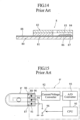
- Figs. 13 and 14 show another biosensor (see Patent Document 1, for example).
- the elements which are identical or similar to those of the biosensor 8 shown in Figs. 9-11 are designated by the same reference signs as those used for the biosensor 8.
- the biosensor 8' further includes a detection electrode 88 in addition to the working electrode 86 and the counter electrode 87.
- the detection electrode 88 is utilized for determining whether or not blood is introduced into the capillary 84, and the portion of the detection electrode which is to come into contact with blood is provided on a downstream side in the blood flow direction (deeper side) in the capillary 84.
- the fact that the blood has reached the detection electrode 88 means that the blood has reached both of the working electrode 86 and the counter electrode 87 and thus means that a sufficient amount of blood is introduced into the capillary 84.
- a blood glucose level measuring apparatus as shown in Fig. 15 is used.
- the elements which are identical or similar to those of the blood glucose level measuring apparatus 9 shown in Fig. 12 are designated by the same reference signs as those used for the blood glucose level measuring apparatus 9.
- the blood glucose level measuring apparatus 9' further includes a connector 94 for coming into contact with the detection electrode 88 in addition to the connectors 90 and 91.
- the connector 94 is connected to ground. Specifically, by opening or closing the switch 96 by a CPU 95, the connector 91 is connected to ground or not connected to ground.
- the blood glucose level measuring apparatus 9' determines that blood is introduced into the capillary 84 when electrical connection between the detection electrode 88 and the working electrode 86 is detected, with the switch 96 closed. Further, with the switch 96 opened, the blood glucose level measuring apparatus 9' applies a voltage across the working electrode 86 and the counter electrode 87 via connectors 90, 91 and measures the response current obtained at the time. The blood glucose -level is computed based on the response current measured after the lapse of a predetermined period from the detection of the blood introduction.
- the biosensor 8' includes a detection electrode 88, and the portion of the detection electrode 88 which is to come into contact with blood is provided on a deeper side relative to the portion of the working electrode 86 and the counter electrode 87 which is to come into contact with blood.
- the determination that blood is introduced into the capillary 84 is made only when the amount of the blood introduced into the capillary 84 is sufficient.
- the provision of the detection electrode 88 for detecting blood introduction into the capillary 84 in addition to the working electrode 86 and the counter electrode 87 increases the manufacturing cost of the biosensor 8'.
- the blood glucose level measuring apparatus 9' used for the biosensor 8' requires the additional connector 94 for the detection electrode 88. Moreover, it is also necessary to provide the switch 96 for selecting the state in which the connector 94 is connected to ground or the state in which the connector is not connected to ground and to control the on/off operation of the switch 96. Thus, as compared with the blood glucose level measuring apparatus 9 (see Fig. 12 ) used for the biosensor 8 (see Figs. 9-12 ) which does not include a detection electrode 88, this blood glucose level measuring apparatus has a complicated structure and needs various control. Thus, the manufacturing cost of the blood glucose level measuring apparatus 9' is higher than that of the blood glucose level measuring apparatus 9 (see Fig. 12 ).
- Patent Document 1 JP-A-2001-208715
- EP 1 541 998 A1 EP 0 987 544 A1
- EP 1 281 955 A1 WO 2005/054840 A1
- WO 2004/051249 A1 WO 2004/038397 A1 .
- EP 1 541 998 A1 discloses a sample analyzer which includes : a voltage applier for applying a voltage to a reaction field which includes a sample; a response measurer for measurement of a response to the voltage applied to the reaction field; a selector for selecting a first voltage application state for measurement of a first response for use in calculation necessary for analyzing the sample or a second voltage application state for measurement of a second response for use in determining whether or not the reaction field has been supplied with a target amount of the sample; an arithmetic operator for calculation necessary for analyzing the sample based on the first response; a determiner for determination, based on the second response, on whether or not the reaction field has been supplied with the target amount of sample; and a controller which makes the selector select the second voltage application state after making the selector select the first voltage application state.
- EP 0 987 544 A1 discloses a method for determining the concentration of a substrate in a sample solution using an electrode system comprising a working electrode and a counter electrode, both being formed on an electrically insulating base plate, and a reaction layer which contains at least an oxidoreductase and an electron mediator and is formed on the electrode system to electrochemically measure a reduced amount of the electron mediator resulting from enzyme reaction in the reaction layer, wherein a third electrode is formed as an interfering substance detecting electrode somewhere apart from the reaction layer to detect supply of the sample solution on the basis of an electrical change between the counter electrode and the third electrode. A current flowing between the counter electrode and the third electrode is measured which is taken as a positive error. Subsequently, voltage application between the counter electrode and the third electrode is released and a voltage for oxidizing the reduced form electron mediator is applied between the working electrode and the counter electrode to measure a current flowing between the two electrodes.
- EP 1 281 955 A1 discloses a biosensor comprising: an electrode system including a measuring electrode, a counter electrode, and a detecting electrode on a first electrically insulating support; a specimen supply path for introducing the sample liquid; and a reagent layer used for quantifying a substrate contained in the sample liquid.
- the detecting electrode is spaced from the measuring electrode by a distance sufficient for the sample liquid to sufficiently cover the measuring electrode before the sample liquid reaches the detecting electrode.
- WO 2005/054840 A1 discloses a method for correctably determining a blood component by measuring the hematocrit (Hct) value of the blood, and a sensor used for the method.
- a blood component measuring sensor has first and second analyzing sections.
- the first analyzing section includes a first electrode system and a reagent layer which has a redox enzyme for a blood component and a mediator.
- the first analyzing section redoxes the blood component with the redox enzyme in the presence of the mediator.
- the first electrode detects the redox current when a voltage is applied to determine the blood component.
- the second analyzing section has a working electrode and a counter electrode. No mediator is provided to the working electrode, and a mediator is provided to the counter electrode.
- the blood is introduced into the electrode system, a voltage is applied, and the current flowing is detected. In this way, the Hct value of the blood is determined, and the amount of blood component can be corrected referring to this Hct value.
- WO 2004/051249 A1 discloses an analytical tool to be mounted to an analytical apparatus which includes a plurality of terminals and an analysis circuit.
- the analytical tool includes a plurality of electrodes coming into contact with the plurality of terminals when mounted to the analytical apparatus.
- at least one of the electrodes serves as a disturbing-noise countermeasure electrode to which disturbing noise is more likely to come in comparison with the other electrodes.
- WO 2004/038397 A1 discloses an analytical tool comprising a substrate, and a capillary disposed on the substrate and adapted to be charged with a sample liquid by internally moving the sample liquid.
- the substrate is provided with a liquid movement inhibition means for inhibiting the sample liquid charged into the capillary from moving.
- the liquid movement inhibition means is installed at a step projecting from the substrate or installed at the substrate and is constructed preferably as having a recess, for example.
- An object of the present invention is to reliably detect the lack of sample supply to a capillary of an analytical tool to prevent incorrect measurements due to the sample lack while preventing an increase in the manufacturing cost of an analytical tool and an analytical apparatus by employing a simple structure .
- the present invention is an analytical tool as defined in Claim 1 of the appended claims, suitable for mounting to an analytical apparatus. Details of certain embodiments are set out in the dependent claims.
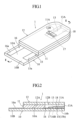
- the biosensor 1 shown in Figs. 1-3 is a disposable one which is mounted in use to a blood glucose level measuring apparatus 2 (see Fig. 5 ) .
- the biosensor 1 includes a substrate 10 which is generally in the form of an elongated rectangle and a cover 12 bonded to the substrate via a spacer 11. These elements 10-12 define a capillary 13 extending in the longitudinal direction of the substrate 10 in the biosensor 1.
- the spacer 11 defines the distance from the upper surface 10A of the substrate 10 to the lower surface 12A of the cover 12, i.e., the height of the capillary 13 and may comprise a double-sided tape.
- the spacer 11 is formed with a slit 11A having an open end.
- the slit 11A defines the width of the capillary 13.
- the open end of the slit 11A provides an introduction port 13A for introducing blood into the capillary 13.
- the cover 12 is formed with an exhaust port 12B for discharging gas from the capillary 13.
- the cover 12 is made of a thermoplastic resin having a high wettability such as Vinylon or highly crystalline PVA, for example.
- the substrate 10 is made of an insulating resin material such as PET and is made larger than the cover 12.
- the substrate 10 includes an end 10B projecting sideways of the cover 12.
- the upper surface 10A of the substrate 10 is formed with a working electrode 15, a counter electrode 16, an insulating mask 17 and a reagent layer 18.
- the working electrode 15 and the counter electrode 16 are used for applying a voltage to the blood introduced into the capillary 13 and respectively include ends 15a and 16a which are not covered by the cover 12 and exposed at the end 10B of the substrate 10.
- the ends 15a and 16a come into contact with terminals 20 and 21 (see Fig. 5 ) of the blood glucose level measuring apparatus 2.
- the working electrode 15 further includes an end 15b which extends in the widthwise direction of the substrate 10 and part of which is positioned within the capillary 13.
- the counter electrode 16 includes an S-shaped bent portion 16A.
- the bent portion 16A surrounds the end 15b of the working electrode 15.
- the counter electrode 16 is divided at the bent portion 16A in the capillary 13 by a slit 16B extending in the longitudinal direction of the substrate 10 (the direction of blood movement in the capillary 13).
- the counter electrode 16 is made up of a first portion 16C including the end 16a, and a second portion 16D, i.e., the portion other than the first portion, which includes the portion surrounding the end 15b of the working electrode 15.
- the working electrode 15 and the counter electrode 16 can be formed simultaneously by screen printing using a conductive carbon ink.
- the insulating mask 17 prevents the working electrode 15 and the counter electrode 16 from short-circuiting and includes a slit 17A.
- the slit 17A exposes intended portions of the working electrode 15 and the counter electrode 16 within the capillary 13 and defines a region for providing the reagent layer 18.
- portions of the working electrode 15 and the counter electrode 16 which are in contact with the reagent layer 18 provide active portions 15c, 16b, 16c, 16d.
- the active portion 16b, the active portion 15c, and the active portions 16c and 16d are arranged in the blood flow direction in the mentioned order.
- the active portions 16c and 16d of the counter electrode 16 substantially serve as a detection electrode.
- the insulating mask 17 is not limited to the illustrated example and may have another shape as long as it includes an opening for providing the reagent layer 18.
- the opening may have a shape other than the slit.
- the insulating mask may have a shape which is similar to the cover 11 in plan view (i.e. , the structure covering the portions other than the ends 15a, 16a and the active portions 15c, 16b, 16c, 16d of the working electrode 15 and the counter electrode 16).
- the reagent layer 18 is arranged in the slit 17A of the insulating mask 17 to continuously cover the active portions 15c, 16b, 16c, 16d of the working electrode 15 and the counter electrode 16.
- the reagent layer 18 may contain an electron mediator and an oxidoreductase.
- the reagent layer 18 is in a porous solid state which easily dissolves in blood.
- the electron mediator use may be made of a ruthenium complex or an iron complex, and [Ru(NH 3 ) 6 ]Cl 3 or K 3 [Fe(CN) 6 ] may be typically used.
- the oxidoreductase use may be made of glucose oxidase (GOD) or glucose dehydrogenase (GDH), and PQQGDH may be typically used.
- the regent layer does not necessarily need to continuously cover the active portions 15c, 16b, 16c, 16d of the working electrode 15 and the counter electrode 16.
- a plurality of separate reagent layers such as a first reagent layer which covers the active portions 15c, 16b and a second reagent layer which is provided separately from the first reagent layer and covers the active portions 16c, 16d may be provided.
- the reagent layers may contain different reagents.
- the capillary 13 is utilized for moving the blood introduced from the introduction port 13A in the longitudinal direction of the substrate 10 by capillary action and retaining the introduced blood. Specifically, when blood is introduced into the capillary 13 through the introduction port 13A, the blood moves while discharging gas from the capillary 13 through the exhaust port 12B. In this process, the reagent layer 18 in the capillary 13 is dissolved to establish a liquid phase reaction system containing electron mediator, oxidoreductase and glucose. The movement of the blood in the capillary 13 is stopped when the blood reaches an edge of the exhaust port 12B.
- Figs. 4A and 4B show the case in which the amount of blood BL introduced into the capillary 13 is insufficient and the active portion 15c of the working electrode 15 and the active portion 16c of the first portion 16C of the counter electrode 16 are not electrically connected to each other via the blood BL. In this case, electric current does not flow in the biosensor 1.
- FIG. 4C shows the case in which the active portion 15c of the working electrode 15 and the active portion 16c of the first portion 16C of the counter electrode 16 are electrically connected to each other via the blood BL, but the active portion 16d of the second portion 16D of the counter electrode 16 and the active portion 15c of the working electrode 15 are not electrically connected via the blood (i.e., the active portion 16c of the first portion 16C and the active portion 16d of the second portion 16D of the counter electrode 16 are not electrically connected to each other) .
- Fig. 4D shows the case in which the active portion 16c of the first portion 16C and the active portion 16d of the second portion 16D of the counter electrode 16 are electrically connected to each other only at portions thereof. In the cases shown in Figs.
- the blood glucose level measuring apparatus 2 shown in Fig. 5 is an apparatus for measuring the glucose level (blood glucose level) of the blood supplied to the biosensor 1 and includes terminals 20 and 21, a current-voltage conversion circuit 22, an A/D conversion circuit 23 and a control/arithmetic circuit 24.
- the terminals 20 and 21 are portions to come into contact with the ends 15a and 16a of the working electrode 15 and the counter electrode 16 of the biosensor 1 and used for forming a potential difference between the working electrode 15 and the counter electrode 16.
- the terminal 20 is connected to the current-voltage conversion circuit 22, whereas the terminal 21 is connected to ground.
- the current-voltage conversion circuit 22 converts current to voltage (analog signals) for outputting and is connected to the terminal 20 and the A/D conversion circuit 23.
- the A/D conversion circuit 23 converts the analog signals outputted from the current-voltage conversion circuit 22 into digital signals for outputting and is connected to the current-voltage conversion circuit 22 and the control/arithmetic circuit 24.
- the control/arithmetic circuit 24 controls various elements and determines whether or not blood is introduced into the capillary 13 and whether or not the amount of the blood introduced into the capillary 13 is sufficient or computes the blood glucose level based on the digital signals outputted from the A/D conversion circuit 23.
- the control/arithmetic circuit 24 may comprise a CPU, a RAM and a ROM.
- the blood glucose level measurement is performed automatically in the blood glucose level measuring apparatus 2 when the biosensor 1 is mounted to the blood glucose level measuring apparatus 2 and blood is supplied to the biosensor 1.
- the ends 15a, 16a of the working electrode 15 and the counter electrode 16 of the biosensor 1 come into contact with the terminals 20, 21 of the blood glucose level measuring apparatus 2.
- the blood introduced into the capillary 13 of the biosensor 1 through the introduction port 13A moves toward the exhaust port 12B due to the capillary action which occurs in the capillary 13.
- the reagent layer 18 is quickly dissolved by the blood, whereby a liquid phase reaction system is established in the capillary 13.
- oxidoreductase reacts specifically with glucose in the blood to take electrons from glucose, and the electrons are transferred to the electron mediator, whereby the electron mediator becomes the reduced form.
- a potential difference is formed between the terminals 20 and 21, so that a potential difference is formed between the working electrode 15 and the counter electrode 16.
- the current is converted into voltage at the current-voltage conversion circuit 22 to be inputted into the A/D conversion circuit 23 and then outputted from the A/D conversion circuit 23 as a digital signal corresponding to the level of the current.
- the digital signal is inputted into the control/arithmetic circuit 24.
- the blood reaches the active portions 16c, 16d of the first portion 16C of the counter electrode 16 immediately after the introduction.
- the active portions 16c, 16d and the active portion 15c of the working electrode 15 are electrically connected to each other, and the regent layer 18 dissolves quickly.
- the time course of the digital signals (magnitude of the response current) inputted into the control/arithmetic circuit 24 is like that indicated by the solid lines in Fig. 6 .
- the response current reaches the peak immediately after the blood is introduced into the capillary 13 and then decreases monotonically.
- the solid line with a relatively high peak indicates the time course in the case where the blood glucose level is at a medium or high level
- the solid line with a relatively low peak indicates the time course in the case where the blood glucose level is at a low level.
- the time course of the response current is like that schematically indicated by the chain line, the single-dashed line and the double-dashed line in the figure.
- the blood does not reach the entirety of the active portions 16c, 16d of the first portion 16B of the counter electrode 16 immediately after the blood is introduced (see Figs. 4A-4D , for example), and the reagent layer 18 does not dissolve quickly.
- the response current monotonically increases within a low range as schematically indicated by the chain line in the figure or reaches the peak later than in the normal state as schematically indicated by the single-dashed line in the figure.
- the response current reaches the peak at a similar timing to the normal state, the response current does not decrease monotonically after the peak, i.e., the response current starts to increase monotonically or reaches another peak after a certain period from the peak.
- the response current may fluctuate after the first peak.
- the control/arithmetic circuit 24 successively grasps the level of the inputted digital signal (magnitude of the current) at predetermined time intervals and determines whether or not the level is higher than a predetermined threshold.
- the threshold may be set to a value corresponding to the current that flows when the active portion 16c of the first portion 16C and the active portion 16d of the second portion 16D of the counter electrode 16 are properly connected to each other electrically.
- the control/arithmetic circuit 24 sets the point of the determination as a zero point and grasps the level of the inputted digital signal at predetermined time intervals (e.g. intervals of 200 msec).
- the control/arithmetic circuit 24 determines whether or not a sufficient amount of blood is supplied to the capillary 13 based on the digital signals obtained successively.
- This determination process includes a peak detection step of determining whether or not the peak of the time course appears after the lapse of a predetermined period (e.g. 0.1 to 3.0 seconds) from the zero point, a monotonic decrease detection step of determining whether or not the response current monotonically decreases after the peak in the case where the peak is detected in the peak detection step, and a determination step of determining whether or not a sufficient amount of blood is supplied to the capillary 13 based on the determination results of the peak detection step and the monotonic decrease detection step.
- a predetermined period e.g. 0.1 to 3.0 seconds
- the control/arithmetic circuit 24 determines in the determination step that a sufficient amount of blood is not supplied to the capillary 13. Owing to such determination, when the amount of blood is insufficient so that the time course of the response current is like that schematically indicated by the chain line or the single-dashed line in Fig. 6 , the fact that a sufficient amount of blood is not supplied to the capillary 13 is properly detected.
- the control/arithmetic circuit 24 determines in the determination step that a sufficient amount of blood is not supplied to the capillary 13. Owing to such determination, when the amount of blood is insufficient so that the time course of the response current is like that schematically indicated by the double-dashed line or the response current fluctuates after the peak, the fact that a sufficient amount of blood is not supplied to the capillary 13 is properly detected.
- control/arithmetic circuit 24 When it is determined that a sufficient amount of blood is not supplied to the capillary 13, the control/arithmetic circuit 24 performs error handling without performing the computation of the blood glucose level and finishes the blood glucose level measurement process.
- the fact that error handling is performed is displayed at e.g. a display panel (not shown) of the blood glucose level measuring apparatus 2.
- the control/arithmetic circuit 24 determines that a sufficient amount of blood is supplied to the capillary 13 and proceeds the blood glucose level measurement. Specifically, the control/arithmetic circuit 24 samples the response current value (level of the digital signal from the A/D conversion circuit 23) measured when a predetermined period (e.g. five seconds) has lapsed from the time point at which the blood introduction into the capillary 13 is detected (i.e. zero point) and applies the sampled response current value to a calibration curve prepared in advance . Thus, the blood glucose level is computed. The result of the blood glucose level computation is displayed at e.g. a display panel (not shown) of the blood glucose level measuring apparatus 2.
- a predetermined period e.g. five seconds
- the counter electrode 16 of the biosensor 1 is divided within the capillary 13, as described above.
- the magnitude of the measured current differs greatly between when the amount of the blood introduced into the capillary 13 is sufficient and when the blood is insufficient.
- the lack of the amount of the blood introduced into the capillary 13 is reliably detected.
- the active portions 16c, 16d of the counter electrode 16 which substantially function as detection electrodes, are provided downstream in the blood flow direction from the active portion 16b of the counter electrode 16 and the active portion 15c of the working electrode 15, the fact that the blood has reached the active portion 16b of the counter electrode 16 and the active portion 15c of the working electrode 15 is reliably detected.
- biosensor 1 advantages of the biosensor 1 are obtained just by devising the shape of the counter electrode 16 and dividing the counter electrode 16 without providing an additional detection electrode like that provided in the conventional structure. Thus, in the biosensor 1, the introduction of blood into the capillary 13 is reliably detected without increasing the manufacturing cost.
- the amount of the blood introduced into the capillary 13 is sufficient is determined by grasping the time course of the response current and checking the presence or absence of the peak of the time course or the behavior of the response current after the peak (i.e., whether or not the response current monotonically decreases) if the peak exists.
- the lack of the amount of the blood introduced into the capillary 13 is reliably detected. Since the biosensor 1 does not include a detection electrode, this advantage of the blood glucose level measuring apparatus 2 is obtained without the need for providing a terminal or a switch for a detection electrode and controlling the on/off operation of a switch.
- the introduction of blood into the capillary 13 is reliably detected without increasing the manufacturing cost.
- the lack of the amount of the blood introduced into the capillary 13 is reliably detected with an inexpensive structure by devising the shape of the counter electrode 16 of the biosensor 1 and devising the data processing of the response current obtained in the blood glucose level measuring apparatus 2.
- the situation in which the amount of the blood introduced into the capillary 13 is so insufficient that an unduly low measurement value will be obtained if measurement is performed is properly handled as an error.
- the situation in which the blood glucose level is actually low is properly distinguished from the situation in which the amount of the blood introduced is insufficient.
- the reliability of the measurement of a low blood glucose level is enhanced.
- biosensors will be described below with reference to Figs. 7A and 7B , and Figs. 8A-8C .
- Figs. 7A and 7B the elements which are identical or similar to those of the biosensor 1 described above with reference to Figs. 1-3 are designated by the same reference signs as those used for the biosensor 1.
- Figs. 8A-8C the elements which are identical or similar to those of the biosensor 8 described with reference to Figs. 10-12 are designated by the same reference signs as those used for the biosensor 8.
- the counter electrode 30A has a structure obtained by dividing the counter electrode of the foregoing biosensor 1 (see Figs. 1-3 ) at a portion on a deeper side of the capillary 13 along the direction (widthwise direction of the substrate 10) crossing the blood flow direction (longitudinal direction of the substrate 10).
- the active portions 31A and 32A are arranged along the longitudinal direction of the substrate 10.
- the counter electrode 30B is divided within the capillary 13 in both of the blood flow direction (longitudinal direction of the substrate 10) and the direction (widthwise direction of the substrate 10) crossing the blood flow direction.
- the biosensors 4A, 4B, 4C shown in Figs. 8A-8C which do not represent embodiments of the present invention, include working electrodes 40A, 40B, 40C having a shape obtained by dividing the working electrode of the conventional biosensor 8 (see Figs. 10-12 ) within the capillary 84.
- the working electrode 40A is divided along the blood flow direction (longitudinal direction of the substrate 80) .
- the working electrode 40B is divided along the direction (widthwise direction of the substrate 80) crossing the blood flow direction (longitudinal direction of the substrate 80).
- the working electrode 40C is divided along both of the blood flow direction (longitudinal direction of the substrate 80) and the direction (widthwise direction of the substrate 80) crossing the blood flow direction.
- the manner of dividing part of the working electrode and the counter electrode is not limited to the examples shown in Figs. 1-3 , 7 and 8 .
- the electrodes may be divided by a slit obliquely crossing the blood flow direction or a nonlinear slit such as a curved slit.
- the application of the method of detecting blood supply lack described above i.e., detection based on the presence or absence of the peak of the time course of the response current or the behavior of the response current after the lapse of a predetermined period from the blood introduction (i.e., whether or not the response current monotonically decreases) is not limited to a biosensor in which the working electrode or the counter electrode is divided.
- the method is also applicable to the blood glucose level measurement using a conventional biosensor including a working electrode or a counter electrode which is not divided (see Figs. 10-12 ). In this case, when a peak is detected again after the detection of a peak (i.e., when the time course is like that schematically indicated by the double-dashed line in Fig. 6 ), it may be determined that the ejection of blood has occurred.
- the present invention is not only to be used with an analytical apparatus which uses a biosensor for measuring a blood glucose level but also with an analytical apparatus which uses other analytical tools.
- the present invention is also applicable to an analytical tool designed to measure a component other than glucose in blood (e.g. lactic acid or cholesterol) or an analytical tool designed to analyze a sample other than blood.
Landscapes
- Health & Medical Sciences (AREA)
- Life Sciences & Earth Sciences (AREA)
- Chemical & Material Sciences (AREA)
- Biochemistry (AREA)
- Chemical Kinetics & Catalysis (AREA)
- Electrochemistry (AREA)
- Physics & Mathematics (AREA)
- Analytical Chemistry (AREA)
- Molecular Biology (AREA)
- General Health & Medical Sciences (AREA)
- General Physics & Mathematics (AREA)
- Immunology (AREA)
- Pathology (AREA)
- Hematology (AREA)
- Biophysics (AREA)
- Investigating Or Analysing Biological Materials (AREA)
Claims (4)
- Outil analytique (1) convenant à un montage sur un appareil analytique (2),l'outil analytique (1) comprenant un substrat (10), un couvercle (12), et une pièce d'espacement (11) entre le couvercle (12) et le substrat (10), dans lequel le substrat (10), la pièce d'espacement (11) et le couvercle (12) définissent un capillaire (13) qui s'étend suivant une direction longitudinale du substrat (10), dans lequel le capillaire (13) forme un trajet d'écoulement (13) pour déplacer un échantillon, le capillaire (13) comprenant un port d'introduction (13A) pour introduire l'échantillon dans le capillaire, et l'outil analytique (1) comprenant en outre une électrode de travail (15) et une contre-électrode (16) pour appliquer une tension à l'échantillon fourni au trajet d'écoulement (13), l'électrode de travail (15) et la contre-électrode (16) étant formées sur le substrat (10) ;dans lequel l'électrode de travail (15) comprend une première portion active (15c) qui est positionnée au sein du trajet d'écoulement (13) pour se mettre en contact avec l'échantillon et une extrémité de contact exposée (15a) qui est positionnée à l'extérieur du trajet d'écoulement (13) pour un contact avec une première borne (20) de l'appareil analytique (2), etla contre-électrode (16) comprend une première portion (16C), la première portion (16C) incluant une deuxième portion active (16c) qui est positionnée au sein du trajet d'écoulement (13) pour se mettre en contact avec l'échantillon et une extrémité de contact exposée (16a) qui est positionnée à l'extérieur du trajet d'écoulement (13) pour un contact avec une deuxième borne (21) de l'appareil analytique (2) ;l'outil analytique (1) ne comprenant aucune extrémité de contact supplémentaire, sauf l'extrémité de contact exposée (15a) de l'électrode de travail (15) et l'extrémité de contact exposée (16a) de la contre-électrode (16), les extrémités de contact (15a, 16a) servant à une mise en contact de l'électrode de travail (15) et de la contre-électrode (16) avec les première et deuxième bornes (20, 21) de l'appareil analytique (2) ;caractérisé en ce quela contre-électrode (1) comprend en outre une deuxième portion (16D) qui est formée sur le substrat (10), la deuxième portion (16D) incluant une troisième portion active (16b) et une quatrième portion active (16d) qui sont toutes deux positionnées au sein du trajet d'écoulement (13), la troisième portion active (16b) étant positionnée sur un côté de la première portion active (15c) et la quatrième portion active (16d) étant positionnée sur le côté opposé de la première portion active (15c),la deuxième portion (16D) est séparée de manière physique et électrique de la première portion (16C), en vertu de quoi la quatrième portion active (16d) est séparée de manière physique et électrique de la deuxième portion active (16c) par une fente (16B) qui s'étend dans la direction longitudinale du substrat (10) au sein du trajet d'écoulement (13), etla troisième portion active (16b), la première portion active (15c) et à la fois la deuxième portion active (16c) et la quatrième portion active (16d) sont agencées dans l'ordre mentionné à partir du port d'introduction (13A) le long de la direction d'écoulement d'échantillon dans le trajet d'écoulement (13).
- Outil analytique selon la revendication 1, dans lequel la deuxième portion active (16c) et la quatrième portion active (16d) sont agencées le long d'une direction qui croise la direction d'écoulement d'échantillon dans le trajet d'écoulement (13).
- Outil analytique selon la revendication 1, comprenant en outre une couche de réactif (18) laquelle couvre en continu la troisième portion active (16b), la première portion active (15c) et à la fois la deuxième portion active (16c) et la quatrième portion active (16d), et contenant un médiateur à électrons.
- Outil analytique selon la revendication 1, dans lequel le trajet d'écoulement (13) est configuré pour déplacer l'échantillon grâce à l'action capillaire.
Applications Claiming Priority (3)
| Application Number | Priority Date | Filing Date | Title |
|---|---|---|---|
| JP2005255219 | 2005-09-02 | ||
| EP06796932.9A EP1939611B1 (fr) | 2005-09-02 | 2006-08-29 | Procédé pour détecter la condition de livraison d'un échantillon et analyseur |
| PCT/JP2006/316952 WO2007026683A1 (fr) | 2005-09-02 | 2006-08-29 | Procédé pour détecter la condition de livraison d'un échantillon et analyseur |
Related Parent Applications (2)
| Application Number | Title | Priority Date | Filing Date |
|---|---|---|---|
| EP06796932.9A Division-Into EP1939611B1 (fr) | 2005-09-02 | 2006-08-29 | Procédé pour détecter la condition de livraison d'un échantillon et analyseur |
| EP06796932.9A Division EP1939611B1 (fr) | 2005-09-02 | 2006-08-29 | Procédé pour détecter la condition de livraison d'un échantillon et analyseur |
Publications (2)
| Publication Number | Publication Date |
|---|---|
| EP2916126A1 EP2916126A1 (fr) | 2015-09-09 |
| EP2916126B1 true EP2916126B1 (fr) | 2024-07-31 |
Family
ID=37808772
Family Applications (2)
| Application Number | Title | Priority Date | Filing Date |
|---|---|---|---|
| EP15163425.0A Active EP2916126B1 (fr) | 2005-09-02 | 2006-08-29 | Outil analytique de détection d'état d'alimentation d'échantillon |
| EP06796932.9A Active EP1939611B1 (fr) | 2005-09-02 | 2006-08-29 | Procédé pour détecter la condition de livraison d'un échantillon et analyseur |
Family Applications After (1)
| Application Number | Title | Priority Date | Filing Date |
|---|---|---|---|
| EP06796932.9A Active EP1939611B1 (fr) | 2005-09-02 | 2006-08-29 | Procédé pour détecter la condition de livraison d'un échantillon et analyseur |
Country Status (7)
| Country | Link |
|---|---|
| US (1) | US8430999B2 (fr) |
| EP (2) | EP2916126B1 (fr) |
| JP (1) | JPWO2007026683A1 (fr) |
| KR (1) | KR101009365B1 (fr) |
| CN (1) | CN101253405B (fr) |
| TW (1) | TW200722746A (fr) |
| WO (1) | WO2007026683A1 (fr) |
Families Citing this family (15)
| Publication number | Priority date | Publication date | Assignee | Title |
|---|---|---|---|---|
| TW200912298A (en) * | 2007-04-12 | 2009-03-16 | Arkray Inc | Analyzing tool |
| EP2211172B1 (fr) * | 2007-10-31 | 2022-03-30 | ARKRAY, Inc. | Procédé de fabrication d'un outil d'analyse |
| US20110057671A1 (en) * | 2009-09-04 | 2011-03-10 | Lifescan Scotland, Ltd. | Methods, system and device to identify a type of test strip |
| KR101033649B1 (ko) * | 2009-09-04 | 2011-05-12 | 주식회사 필로시스 | 자동코드인식을 위한 바이오센서 및 이를 이용한 코드인식방법 |
| WO2012140888A1 (fr) * | 2011-04-12 | 2012-10-18 | パナソニック株式会社 | Biocapteur de dispositif de mesure l'utilisant |
| US9733205B2 (en) | 2011-06-16 | 2017-08-15 | Panasonic Healthcare Holdings Co., Ltd. | Sensor and sensor system equipped with same |
| JP2013257310A (ja) * | 2012-05-18 | 2013-12-26 | Arkray Inc | バイオセンサ |
| US9523653B2 (en) | 2013-05-09 | 2016-12-20 | Changsha Sinocare Inc. | Disposable test sensor with improved sampling entrance |
| US9435764B2 (en) * | 2013-06-27 | 2016-09-06 | Lifescan Scotland Limited | Transient signal error trap for an analyte measurement determined from a specified sampling time derived from a sensed physical characteristic of the sample containing the analyte |
| US9518951B2 (en) | 2013-12-06 | 2016-12-13 | Changsha Sinocare Inc. | Disposable test sensor with improved sampling entrance |
| US9897566B2 (en) | 2014-01-13 | 2018-02-20 | Changsha Sinocare Inc. | Disposable test sensor |
| US9939401B2 (en) | 2014-02-20 | 2018-04-10 | Changsha Sinocare Inc. | Test sensor with multiple sampling routes |
| JP6750628B2 (ja) * | 2015-09-18 | 2020-09-02 | パナソニック株式会社 | 化学物質濃縮器および化学物質検出装置 |
| TWI596335B (zh) * | 2015-09-23 | 2017-08-21 | 達爾生技股份有限公司 | 電化學感測試片之檢測方法及檢測裝置 |
| KR20210020578A (ko) * | 2019-08-16 | 2021-02-24 | 동우 화인켐 주식회사 | 바이오 센서 |
Citations (1)
| Publication number | Priority date | Publication date | Assignee | Title |
|---|---|---|---|---|
| WO2004038397A1 (fr) * | 2002-10-25 | 2004-05-06 | Arkray, Inc. | Outil analytique |
Family Cites Families (12)
| Publication number | Priority date | Publication date | Assignee | Title |
|---|---|---|---|---|
| EP0987544B1 (fr) * | 1998-04-02 | 2007-10-17 | Matsushita Electric Industrial Co., Ltd. | Procede de determination d'un substrat |
| DE60025751T2 (de) * | 1999-11-15 | 2006-10-12 | Arkray, Inc. | Biosensor |
| JP4226756B2 (ja) | 1999-11-15 | 2009-02-18 | パナソニック株式会社 | バイオセンサ、それを用いた定量方法及び定量装置 |
| EP2151683A3 (fr) * | 1999-11-15 | 2010-07-28 | Panasonic Corporation | Biocapteur, procédé de formation d'électrode à couche mince, appareil de quantification et procédé de quantification |
| DE60019547T2 (de) * | 1999-12-27 | 2005-10-06 | Matsushita Electric Industrial Co., Ltd., Kadoma | Biosensor |
| EP2388587B1 (fr) * | 2000-11-30 | 2018-01-10 | Panasonic Healthcare Holdings Co., Ltd. | Procédé de quantification de substrat |
| JP3972063B2 (ja) | 2001-01-17 | 2007-09-05 | アークレイ株式会社 | センサを用いる定量分析方法および定量分析装置 |
| JP4120400B2 (ja) * | 2001-04-16 | 2008-07-16 | 松下電器産業株式会社 | バイオセンサ |
| US7083712B2 (en) * | 2001-11-20 | 2006-08-01 | Arkray, Inc. | Fail judging method for analysis and analyzer |
| WO2004011921A1 (fr) * | 2002-07-25 | 2004-02-05 | Arkray, Inc. | Procede et dispositif d'analyse d'echantillon |
| US8460523B2 (en) * | 2002-12-02 | 2013-06-11 | Arkray, Inc. | Analysis instrument |
| CN100472210C (zh) * | 2003-12-04 | 2009-03-25 | 松下电器产业株式会社 | 血液成分的测定方法及该方法中使用的传感器和测定装置 |
-
2006
- 2006-08-29 WO PCT/JP2006/316952 patent/WO2007026683A1/fr not_active Ceased
- 2006-08-29 CN CN2006800318376A patent/CN101253405B/zh active Active
- 2006-08-29 JP JP2007533250A patent/JPWO2007026683A1/ja active Pending
- 2006-08-29 EP EP15163425.0A patent/EP2916126B1/fr active Active
- 2006-08-29 US US11/991,490 patent/US8430999B2/en active Active
- 2006-08-29 EP EP06796932.9A patent/EP1939611B1/fr active Active
- 2006-08-29 KR KR1020087007935A patent/KR101009365B1/ko active Active
- 2006-09-01 TW TW095132350A patent/TW200722746A/zh unknown
Patent Citations (2)
| Publication number | Priority date | Publication date | Assignee | Title |
|---|---|---|---|---|
| WO2004038397A1 (fr) * | 2002-10-25 | 2004-05-06 | Arkray, Inc. | Outil analytique |
| EP1571443A1 (fr) * | 2002-10-25 | 2005-09-07 | ARKRAY, Inc. | Outil analytique |
Also Published As
| Publication number | Publication date |
|---|---|
| US20090120806A1 (en) | 2009-05-14 |
| TWI333063B (fr) | 2010-11-11 |
| EP1939611B1 (fr) | 2015-07-08 |
| CN101253405B (zh) | 2012-10-31 |
| US8430999B2 (en) | 2013-04-30 |
| EP1939611A1 (fr) | 2008-07-02 |
| CN101253405A (zh) | 2008-08-27 |
| EP1939611A4 (fr) | 2011-10-05 |
| KR20080053328A (ko) | 2008-06-12 |
| TW200722746A (en) | 2007-06-16 |
| KR101009365B1 (ko) | 2011-01-19 |
| WO2007026683A1 (fr) | 2007-03-08 |
| EP2916126A1 (fr) | 2015-09-09 |
| JPWO2007026683A1 (ja) | 2009-03-05 |
Similar Documents
| Publication | Publication Date | Title |
|---|---|---|
| AU2008279274B2 (en) | Electrochemical test strip | |
| EP1736763B1 (fr) | Analiseur | |
| EP2916126B1 (fr) | Outil analytique de détection d'état d'alimentation d'échantillon | |
| US8137529B2 (en) | Methods of using an electrochemical biosensor | |
| EP2149792B1 (fr) | Procédé d'analyse d'échantillons | |
| US20090304550A1 (en) | Analytical tool | |
| US20110036729A1 (en) | Control liquid judging method and analysis device | |
| CN102893150B (zh) | 具有包括预定尺寸和分布的电化学活性和惰性区域的电极的分析测试条 | |
| KR101058754B1 (ko) | 생체 시료 정량 측정 방법 및 생체 시료 정량 측정 시스템 | |
| US20080169799A1 (en) | Method for biosensor analysis | |
| AU2013204842B2 (en) | Electrochemical test strip | |
| AU2016200514B2 (en) | Electrochemical test strip | |
| MXPA06008846A (en) | Electrochemical biosensor |
Legal Events
| Date | Code | Title | Description |
|---|---|---|---|
| PUAI | Public reference made under article 153(3) epc to a published international application that has entered the european phase |
Free format text: ORIGINAL CODE: 0009012 |
|
| AC | Divisional application: reference to earlier application |
Ref document number: 1939611 Country of ref document: EP Kind code of ref document: P |
|
| AK | Designated contracting states |
Kind code of ref document: A1 Designated state(s): AT BE BG CH CY CZ DE DK EE ES FI FR GB GR HU IE IS IT LI LT LU LV MC NL PL PT RO SE SI SK TR |
|
| 17P | Request for examination filed |
Effective date: 20160308 |
|
| RBV | Designated contracting states (corrected) |
Designated state(s): AT BE BG CH CY CZ DE DK EE ES FI FR GB GR HU IE IS IT LI LT LU LV MC NL PL PT RO SE SI SK TR |
|
| STAA | Information on the status of an ep patent application or granted ep patent |
Free format text: STATUS: EXAMINATION IS IN PROGRESS |
|
| 17Q | First examination report despatched |
Effective date: 20190315 |
|
| GRAP | Despatch of communication of intention to grant a patent |
Free format text: ORIGINAL CODE: EPIDOSNIGR1 |
|
| STAA | Information on the status of an ep patent application or granted ep patent |
Free format text: STATUS: GRANT OF PATENT IS INTENDED |
|
| INTG | Intention to grant announced |
Effective date: 20240410 |
|
| GRAS | Grant fee paid |
Free format text: ORIGINAL CODE: EPIDOSNIGR3 |
|
| GRAA | (expected) grant |
Free format text: ORIGINAL CODE: 0009210 |
|
| STAA | Information on the status of an ep patent application or granted ep patent |
Free format text: STATUS: THE PATENT HAS BEEN GRANTED |
|
| AC | Divisional application: reference to earlier application |
Ref document number: 1939611 Country of ref document: EP Kind code of ref document: P |
|
| AK | Designated contracting states |
Kind code of ref document: B1 Designated state(s): AT BE BG CH CY CZ DE DK EE ES FI FR GB GR HU IE IS IT LI LT LU LV MC NL PL PT RO SE SI SK TR |
|
| REG | Reference to a national code |
Ref country code: CH Ref legal event code: EP Ref country code: GB Ref legal event code: FG4D |
|
| P01 | Opt-out of the competence of the unified patent court (upc) registered |
Free format text: CASE NUMBER: APP_39079/2024 Effective date: 20240701 |
|
| REG | Reference to a national code |
Ref country code: DE Ref legal event code: R096 Ref document number: 602006060592 Country of ref document: DE |
|
| REG | Reference to a national code |
Ref country code: IE Ref legal event code: FG4D |
|
| REG | Reference to a national code |
Ref country code: LT Ref legal event code: MG9D |
|
| REG | Reference to a national code |
Ref country code: NL Ref legal event code: MP Effective date: 20240731 |
|
| PG25 | Lapsed in a contracting state [announced via postgrant information from national office to epo] |
Ref country code: PT Free format text: LAPSE BECAUSE OF FAILURE TO SUBMIT A TRANSLATION OF THE DESCRIPTION OR TO PAY THE FEE WITHIN THE PRESCRIBED TIME-LIMIT Effective date: 20241202 |
|
| REG | Reference to a national code |
Ref country code: AT Ref legal event code: MK05 Ref document number: 1708921 Country of ref document: AT Kind code of ref document: T Effective date: 20240731 |
|
| PG25 | Lapsed in a contracting state [announced via postgrant information from national office to epo] |
Ref country code: PT Free format text: LAPSE BECAUSE OF FAILURE TO SUBMIT A TRANSLATION OF THE DESCRIPTION OR TO PAY THE FEE WITHIN THE PRESCRIBED TIME-LIMIT Effective date: 20241202 |
|
| PG25 | Lapsed in a contracting state [announced via postgrant information from national office to epo] |
Ref country code: FI Free format text: LAPSE BECAUSE OF FAILURE TO SUBMIT A TRANSLATION OF THE DESCRIPTION OR TO PAY THE FEE WITHIN THE PRESCRIBED TIME-LIMIT Effective date: 20240731 Ref country code: NL Free format text: LAPSE BECAUSE OF FAILURE TO SUBMIT A TRANSLATION OF THE DESCRIPTION OR TO PAY THE FEE WITHIN THE PRESCRIBED TIME-LIMIT Effective date: 20240731 Ref country code: GR Free format text: LAPSE BECAUSE OF FAILURE TO SUBMIT A TRANSLATION OF THE DESCRIPTION OR TO PAY THE FEE WITHIN THE PRESCRIBED TIME-LIMIT Effective date: 20241101 Ref country code: PL Free format text: LAPSE BECAUSE OF FAILURE TO SUBMIT A TRANSLATION OF THE DESCRIPTION OR TO PAY THE FEE WITHIN THE PRESCRIBED TIME-LIMIT Effective date: 20240731 |
|
| PG25 | Lapsed in a contracting state [announced via postgrant information from national office to epo] |
Ref country code: BG Free format text: LAPSE BECAUSE OF FAILURE TO SUBMIT A TRANSLATION OF THE DESCRIPTION OR TO PAY THE FEE WITHIN THE PRESCRIBED TIME-LIMIT Effective date: 20240731 |
|
| PG25 | Lapsed in a contracting state [announced via postgrant information from national office to epo] |
Ref country code: LV Free format text: LAPSE BECAUSE OF FAILURE TO SUBMIT A TRANSLATION OF THE DESCRIPTION OR TO PAY THE FEE WITHIN THE PRESCRIBED TIME-LIMIT Effective date: 20240731 |
|
| PG25 | Lapsed in a contracting state [announced via postgrant information from national office to epo] |
Ref country code: AT Free format text: LAPSE BECAUSE OF FAILURE TO SUBMIT A TRANSLATION OF THE DESCRIPTION OR TO PAY THE FEE WITHIN THE PRESCRIBED TIME-LIMIT Effective date: 20240731 Ref country code: IS Free format text: LAPSE BECAUSE OF FAILURE TO SUBMIT A TRANSLATION OF THE DESCRIPTION OR TO PAY THE FEE WITHIN THE PRESCRIBED TIME-LIMIT Effective date: 20241130 |
|
| PG25 | Lapsed in a contracting state [announced via postgrant information from national office to epo] |
Ref country code: ES Free format text: LAPSE BECAUSE OF FAILURE TO SUBMIT A TRANSLATION OF THE DESCRIPTION OR TO PAY THE FEE WITHIN THE PRESCRIBED TIME-LIMIT Effective date: 20240731 |
|
| PG25 | Lapsed in a contracting state [announced via postgrant information from national office to epo] |
Ref country code: PL Free format text: LAPSE BECAUSE OF FAILURE TO SUBMIT A TRANSLATION OF THE DESCRIPTION OR TO PAY THE FEE WITHIN THE PRESCRIBED TIME-LIMIT Effective date: 20240731 Ref country code: NL Free format text: LAPSE BECAUSE OF FAILURE TO SUBMIT A TRANSLATION OF THE DESCRIPTION OR TO PAY THE FEE WITHIN THE PRESCRIBED TIME-LIMIT Effective date: 20240731 Ref country code: LV Free format text: LAPSE BECAUSE OF FAILURE TO SUBMIT A TRANSLATION OF THE DESCRIPTION OR TO PAY THE FEE WITHIN THE PRESCRIBED TIME-LIMIT Effective date: 20240731 Ref country code: IS Free format text: LAPSE BECAUSE OF FAILURE TO SUBMIT A TRANSLATION OF THE DESCRIPTION OR TO PAY THE FEE WITHIN THE PRESCRIBED TIME-LIMIT Effective date: 20241130 Ref country code: GR Free format text: LAPSE BECAUSE OF FAILURE TO SUBMIT A TRANSLATION OF THE DESCRIPTION OR TO PAY THE FEE WITHIN THE PRESCRIBED TIME-LIMIT Effective date: 20241101 Ref country code: FI Free format text: LAPSE BECAUSE OF FAILURE TO SUBMIT A TRANSLATION OF THE DESCRIPTION OR TO PAY THE FEE WITHIN THE PRESCRIBED TIME-LIMIT Effective date: 20240731 Ref country code: ES Free format text: LAPSE BECAUSE OF FAILURE TO SUBMIT A TRANSLATION OF THE DESCRIPTION OR TO PAY THE FEE WITHIN THE PRESCRIBED TIME-LIMIT Effective date: 20240731 Ref country code: BG Free format text: LAPSE BECAUSE OF FAILURE TO SUBMIT A TRANSLATION OF THE DESCRIPTION OR TO PAY THE FEE WITHIN THE PRESCRIBED TIME-LIMIT Effective date: 20240731 Ref country code: AT Free format text: LAPSE BECAUSE OF FAILURE TO SUBMIT A TRANSLATION OF THE DESCRIPTION OR TO PAY THE FEE WITHIN THE PRESCRIBED TIME-LIMIT Effective date: 20240731 |
|
| REG | Reference to a national code |
Ref country code: CH Ref legal event code: PL |
|
| PG25 | Lapsed in a contracting state [announced via postgrant information from national office to epo] |
Ref country code: RO Free format text: LAPSE BECAUSE OF FAILURE TO SUBMIT A TRANSLATION OF THE DESCRIPTION OR TO PAY THE FEE WITHIN THE PRESCRIBED TIME-LIMIT Effective date: 20240731 Ref country code: DK Free format text: LAPSE BECAUSE OF FAILURE TO SUBMIT A TRANSLATION OF THE DESCRIPTION OR TO PAY THE FEE WITHIN THE PRESCRIBED TIME-LIMIT Effective date: 20240731 |
|
| PG25 | Lapsed in a contracting state [announced via postgrant information from national office to epo] |
Ref country code: LU Free format text: LAPSE BECAUSE OF NON-PAYMENT OF DUE FEES Effective date: 20240829 |
|
| PG25 | Lapsed in a contracting state [announced via postgrant information from national office to epo] |
Ref country code: MC Free format text: LAPSE BECAUSE OF FAILURE TO SUBMIT A TRANSLATION OF THE DESCRIPTION OR TO PAY THE FEE WITHIN THE PRESCRIBED TIME-LIMIT Effective date: 20240731 Ref country code: EE Free format text: LAPSE BECAUSE OF FAILURE TO SUBMIT A TRANSLATION OF THE DESCRIPTION OR TO PAY THE FEE WITHIN THE PRESCRIBED TIME-LIMIT Effective date: 20240731 Ref country code: CH Free format text: LAPSE BECAUSE OF NON-PAYMENT OF DUE FEES Effective date: 20240831 |
|
| PG25 | Lapsed in a contracting state [announced via postgrant information from national office to epo] |
Ref country code: CZ Free format text: LAPSE BECAUSE OF FAILURE TO SUBMIT A TRANSLATION OF THE DESCRIPTION OR TO PAY THE FEE WITHIN THE PRESCRIBED TIME-LIMIT Effective date: 20240731 |
|
| PG25 | Lapsed in a contracting state [announced via postgrant information from national office to epo] |
Ref country code: SK Free format text: LAPSE BECAUSE OF FAILURE TO SUBMIT A TRANSLATION OF THE DESCRIPTION OR TO PAY THE FEE WITHIN THE PRESCRIBED TIME-LIMIT Effective date: 20240731 |
|
| REG | Reference to a national code |
Ref country code: DE Ref legal event code: R097 Ref document number: 602006060592 Country of ref document: DE |
|
| PLBE | No opposition filed within time limit |
Free format text: ORIGINAL CODE: 0009261 |
|
| STAA | Information on the status of an ep patent application or granted ep patent |
Free format text: STATUS: NO OPPOSITION FILED WITHIN TIME LIMIT |
|
| REG | Reference to a national code |
Ref country code: BE Ref legal event code: MM Effective date: 20240831 |
|
| 26N | No opposition filed |
Effective date: 20250501 |
|
| PG25 | Lapsed in a contracting state [announced via postgrant information from national office to epo] |
Ref country code: BE Free format text: LAPSE BECAUSE OF NON-PAYMENT OF DUE FEES Effective date: 20240831 |
|
| PG25 | Lapsed in a contracting state [announced via postgrant information from national office to epo] |
Ref country code: IE Free format text: LAPSE BECAUSE OF NON-PAYMENT OF DUE FEES Effective date: 20240829 |
|
| PG25 | Lapsed in a contracting state [announced via postgrant information from national office to epo] |
Ref country code: SE Free format text: LAPSE BECAUSE OF FAILURE TO SUBMIT A TRANSLATION OF THE DESCRIPTION OR TO PAY THE FEE WITHIN THE PRESCRIBED TIME-LIMIT Effective date: 20240731 |
|
| PGFP | Annual fee paid to national office [announced via postgrant information from national office to epo] |
Ref country code: DE Payment date: 20250820 Year of fee payment: 20 |
|
| PGFP | Annual fee paid to national office [announced via postgrant information from national office to epo] |
Ref country code: IT Payment date: 20250825 Year of fee payment: 20 |
|
| PGFP | Annual fee paid to national office [announced via postgrant information from national office to epo] |
Ref country code: GB Payment date: 20250821 Year of fee payment: 20 |
|
| PGFP | Annual fee paid to national office [announced via postgrant information from national office to epo] |
Ref country code: FR Payment date: 20250829 Year of fee payment: 20 |
|
| PG25 | Lapsed in a contracting state [announced via postgrant information from national office to epo] |
Ref country code: CY Free format text: LAPSE BECAUSE OF FAILURE TO SUBMIT A TRANSLATION OF THE DESCRIPTION OR TO PAY THE FEE WITHIN THE PRESCRIBED TIME-LIMIT; INVALID AB INITIO Effective date: 20060829 |
|
| PG25 | Lapsed in a contracting state [announced via postgrant information from national office to epo] |
Ref country code: HU Free format text: LAPSE BECAUSE OF FAILURE TO SUBMIT A TRANSLATION OF THE DESCRIPTION OR TO PAY THE FEE WITHIN THE PRESCRIBED TIME-LIMIT; INVALID AB INITIO Effective date: 20060829 |