EP2916147B1 - Barrière de sécurité optoélectronique permettant de détecter des intrusions - Google Patents
Barrière de sécurité optoélectronique permettant de détecter des intrusions Download PDFInfo
- Publication number
- EP2916147B1 EP2916147B1 EP15000514.8A EP15000514A EP2916147B1 EP 2916147 B1 EP2916147 B1 EP 2916147B1 EP 15000514 A EP15000514 A EP 15000514A EP 2916147 B1 EP2916147 B1 EP 2916147B1
- Authority
- EP
- European Patent Office
- Prior art keywords
- image
- camera
- patterns
- safety barrier
- cameras
- Prior art date
- Legal status (The legal status is an assumption and is not a legal conclusion. Google has not performed a legal analysis and makes no representation as to the accuracy of the status listed.)
- Active
Links
Images




Classifications
-
- G—PHYSICS
- G08—SIGNALLING
- G08B—SIGNALLING SYSTEMS, e.g. PERSONAL CALLING SYSTEMS; ORDER TELEGRAPHS; ALARM SYSTEMS
- G08B13/00—Burglar, theft or intruder alarms
- G08B13/18—Actuation by interference with heat, light, or radiation of shorter wavelength; Actuation by intruding sources of heat, light, or radiation of shorter wavelength
- G08B13/189—Actuation by interference with heat, light, or radiation of shorter wavelength; Actuation by intruding sources of heat, light, or radiation of shorter wavelength using passive radiation detection systems
- G08B13/194—Actuation by interference with heat, light, or radiation of shorter wavelength; Actuation by intruding sources of heat, light, or radiation of shorter wavelength using passive radiation detection systems using image scanning and comparing systems
- G08B13/196—Actuation by interference with heat, light, or radiation of shorter wavelength; Actuation by intruding sources of heat, light, or radiation of shorter wavelength using passive radiation detection systems using image scanning and comparing systems using television cameras
- G08B13/19639—Details of the system layout
- G08B13/19641—Multiple cameras having overlapping views on a single scene
-
- F—MECHANICAL ENGINEERING; LIGHTING; HEATING; WEAPONS; BLASTING
- F16—ENGINEERING ELEMENTS AND UNITS; GENERAL MEASURES FOR PRODUCING AND MAINTAINING EFFECTIVE FUNCTIONING OF MACHINES OR INSTALLATIONS; THERMAL INSULATION IN GENERAL
- F16P—SAFETY DEVICES IN GENERAL; SAFETY DEVICES FOR PRESSES
- F16P3/00—Safety devices acting in conjunction with the control or operation of a machine; Control arrangements requiring the simultaneous use of two or more parts of the body
- F16P3/12—Safety devices acting in conjunction with the control or operation of a machine; Control arrangements requiring the simultaneous use of two or more parts of the body with means, e.g. feelers, which in case of the presence of a body part of a person in or near the danger zone influence the control or operation of the machine
- F16P3/14—Safety devices acting in conjunction with the control or operation of a machine; Control arrangements requiring the simultaneous use of two or more parts of the body with means, e.g. feelers, which in case of the presence of a body part of a person in or near the danger zone influence the control or operation of the machine the means being photocells or other devices sensitive without mechanical contact
- F16P3/142—Safety devices acting in conjunction with the control or operation of a machine; Control arrangements requiring the simultaneous use of two or more parts of the body with means, e.g. feelers, which in case of the presence of a body part of a person in or near the danger zone influence the control or operation of the machine the means being photocells or other devices sensitive without mechanical contact using image capturing devices
-
- G—PHYSICS
- G01—MEASURING; TESTING
- G01V—GEOPHYSICS; GRAVITATIONAL MEASUREMENTS; DETECTING MASSES OR OBJECTS; TAGS
- G01V8/00—Prospecting or detecting by optical means
- G01V8/10—Detecting, e.g. by using light barriers
- G01V8/20—Detecting, e.g. by using light barriers using multiple transmitters or receivers
-
- G—PHYSICS
- G06—COMPUTING OR CALCULATING; COUNTING
- G06V—IMAGE OR VIDEO RECOGNITION OR UNDERSTANDING
- G06V20/00—Scenes; Scene-specific elements
- G06V20/50—Context or environment of the image
- G06V20/52—Surveillance or monitoring of activities, e.g. for recognising suspicious objects
-
- G—PHYSICS
- G08—SIGNALLING
- G08B—SIGNALLING SYSTEMS, e.g. PERSONAL CALLING SYSTEMS; ORDER TELEGRAPHS; ALARM SYSTEMS
- G08B13/00—Burglar, theft or intruder alarms
- G08B13/18—Actuation by interference with heat, light, or radiation of shorter wavelength; Actuation by intruding sources of heat, light, or radiation of shorter wavelength
- G08B13/181—Actuation by interference with heat, light, or radiation of shorter wavelength; Actuation by intruding sources of heat, light, or radiation of shorter wavelength using active radiation detection systems
- G08B13/183—Actuation by interference with heat, light, or radiation of shorter wavelength; Actuation by intruding sources of heat, light, or radiation of shorter wavelength using active radiation detection systems by interruption of a radiation beam or barrier
-
- G—PHYSICS
- G08—SIGNALLING
- G08B—SIGNALLING SYSTEMS, e.g. PERSONAL CALLING SYSTEMS; ORDER TELEGRAPHS; ALARM SYSTEMS
- G08B13/00—Burglar, theft or intruder alarms
- G08B13/18—Actuation by interference with heat, light, or radiation of shorter wavelength; Actuation by intruding sources of heat, light, or radiation of shorter wavelength
- G08B13/189—Actuation by interference with heat, light, or radiation of shorter wavelength; Actuation by intruding sources of heat, light, or radiation of shorter wavelength using passive radiation detection systems
- G08B13/194—Actuation by interference with heat, light, or radiation of shorter wavelength; Actuation by intruding sources of heat, light, or radiation of shorter wavelength using passive radiation detection systems using image scanning and comparing systems
- G08B13/196—Actuation by interference with heat, light, or radiation of shorter wavelength; Actuation by intruding sources of heat, light, or radiation of shorter wavelength using passive radiation detection systems using image scanning and comparing systems using television cameras
- G08B13/19602—Image analysis to detect motion of the intruder, e.g. by frame subtraction
-
- G—PHYSICS
- G06—COMPUTING OR CALCULATING; COUNTING
- G06V—IMAGE OR VIDEO RECOGNITION OR UNDERSTANDING
- G06V30/00—Character recognition; Recognising digital ink; Document-oriented image-based pattern recognition
- G06V30/10—Character recognition
- G06V30/14—Image acquisition
- G06V30/144—Image acquisition using a slot moved over the image; using discrete sensing elements at predetermined points; using automatic curve following means
Definitions
- This invention is concerned with an optoelectronic safety barrier for detecting persons or parts of persons entering a passage leading to a forbidden area, such as the environment of an industrial machine in operation, so that the machine can be stopped before an accident occurs.
- a forbidden area such as the environment of an industrial machine in operation
- the invention could be used as well in other kinds of surveillance, e.g., insuring the safety of persons in elevators, watching over areas at risk of thefts, particularly in banks, and other similar tasks.
- Optoelectronic barriers have been used for many years in the surveillance of passages leading to hazardous areas.
- the barriers typically comprise a column bearing an array of infrared LEDs (typically two to four pairs), which send their collimated rays to a corresponding array of photodiodes carried on an opposite column across the passage, whereby the interruption of any ray is detected and considered to be a violation of the passage.
- An example of this type of barrier is described in EP 567 717 .
- the optoelectronic barriers using LEDs and photodiodes are expensive systems, also because of the wiring needed to power, scan and monitor the LEDs and photodiodes on both columns.
- a drawback of the latter type of optoelectronic barrier is that its setup is cumbersome and delicate, as will be evident for the expert in the field, due to the need to ensure a correct alignment between the mirrors, the ray emitted by the LED and the visual field of the photodiode, particularly in view of the IEC 61496-2 standard regulating optoelectronic barriers, which requires that the aperture of the optical beam should be no broader than 5° in barriers classified as Type 4.
- the complexity of the setup increases dramatically when barriers with several LED-photodiode pairs on the same column are to be implemented.
- a main object of the present invention is to provide a safety barrier for protecting gates and the like, which may be a ready substitute for a conventional barrier having columns with reflecting mirrors, and which requires power supply to only one column, while reducing blind areas in the surveillance.
- Another object is to provide a safety barrier as above, whose alignment during setup is easier than for prior barriers, particularly barriers using reflecting mirrors.
- Still another object is to provide said barrier so that it is less sensitive to vibration with respect to barriers with reflecting mirrors.
- a further object is to provide said barrier so that it is less vulnerable to tampering than prior barriers.
- Still another object is to provide a barrier having the above advantages, at a manufacturing cost lower than an equivalent prior barrier.
- D2 US 2012/268274 also discloses a light barrier for detecting intrusions through an opening, which in one embodiment comprises on one side of the opening one or more cameras with overlapping views on a pattern provided on the other side of the opening; the camera views are compared with a reference image, so that any deviation is indicative of intrusion.
- two vertical columns 10, 12, which will be referred to as “active column” and “passive column”, respectively, are located on respective opposite sides of an intervening passage to be monitored, and having a width D equal to the distance between the two columns.
- the active column 10 carries a first camera 14 and a second camera 16 arranged beneath camera 14.
- the cameras 14, 16 have respective conventional light sensors (not shown) and are preferably associated with respective illuminators (also not shown), and have similar optical characteristics with parallel, horizontal optical axes, directed toward the passive column 12, which are spaced with an inter-axial distance H.
- Two patterns 18, 20 are printed or affixed on passive column 12.
- the patterns consist of respective identical square contours or frames, whose centroids are aligned with the optical axes of the respective cameras 14, 16; in other words, the distance h between the centroids of the two patterns is equal to the distance H between the optical axes of the two cameras.
- the rectangular patterns 18, 20 are of a contrasting color with the remaining surface of the column: eg. a contour can be colored black with reflectivity of about 5%, at the wavelength of operation of the sensor, and the internal and external parts can be a highly reflective surface, with a reflectivity of 90%, although other colors are also possible.
- each camera 14, 16 is wide enough to embrace both patterns 18, 20, as shown in 14 ⁇ , 16 ⁇ .
- the two cameras 14, 16 are supplied with power via active column 10 (not shown) and are operatively connected with a control unit 22.
- the control unit 22 cyclically executes a control program which receives the respective output signals of the two cameras 14, 16 and processes them as described below.
- the image A taken by camera 14 will be substantially as shown on Fig. 3 , where the pattern 18 which is aligned with the axis of the lens appears in the center of the image, while the offset pattern 20 is located at a lower position with respect to the horizontal midline of the image denoted as X-X, and its distance from pattern 18 depends on the distance h and the distance D. Since in the preferred case the camera 16 has geometric characteristics and optical properties equal to those of camera 14, its image B of the patterns 18 and 20 will be similar to that generated by camera 14 although in this case pattern 18 is located above the horizontal midline (X-X) of the image, and pattern 20 is aligned with the axis of the lens, and accordingly appears as in Fig. 4 . (It should be understood that Figs.
- FIG. 3 and 4 are respective portions, in the environs of column 12, of the scene shot by the two cameras). Therefore, if the active and passive columns are aligned and parallel to each other, the images of Figs. 3 and 4 will be identical except that they will be vertically overturned about axis X with respect to each other, corresponding to the position of the respective camera (within desired tolerances).
- the images of Fig. 3 and Fig. 4 are then processed, using known techniques of digital processing of images, to convert them to the binary (i.e. black-and-white) images A' of Fig. 5 and B' of Fig. 6 , respectively, thereby extracting the patterns 18 and 20. It is preferred to operate on binary images because the execution of algorithms for comparing or measuring is thus faster and more reliable.
- a binary image can be easily obtained from a grayscale image by setting to black the points of the image having a gray level below a given threshold and, conversely, setting to white all points having a gray level above that threshold.
- the image thus obtained is sure to comprise the two patterns, plus other extraneous black flecks or spots depending on the context of the scene.
- the binary image is then further processed to remove such indesirable black spots, in order to better isolate the patterns.
- a white or gray area of an appreciable width is defined outside the black frame and the black spots that are irregular or unconnected or comprising a number of pixels below a certain value or not containing a number of white pixels are eliminated by means of suitable algorithms.
- FIG. 7 if an opaque cylindrical object 24 is now placed somewhere along the optical axis of camera 14, having a diameter such as to shield pattern 18, the image generated by camera 14 will now be as in Fig. 8 , while the image from camera 16, as shown on Fig. 9 , is still identical to Fig. 4 , because the cylindrical object 24 does not mask any of the two patterns 18 and 20 in the image from that camera.
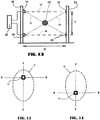
- Figs. 10 and 11 represent the binary images A' and B' generated in this case by the respective cameras after extraction of the patterns.
- the monitoring of the barrier is implemented by cyclically shooting the passive column with both cameras and then continuously comparing the current binary image of the patterns from each camera with a stored reference pattern image, which is the image produced by a camera when the passage is free from intrusions; the control unit will signal a fault condition whenever the two images are not identical; such discrepancy may be due either to internal faults of the cameras or to objects that are introduced into the passage and which therefore mask one or more of said patterns and alter, as mentioned above, the images taken by either or both cameras.
- This method provides the advantage of checking the proper operation of the cameras by "cross-monitoring" their binary pattern images by the intermediary of the reference pattern. This will improve the safety against failure or degradation of one of the cameras, as well as against external tampering, either deliberate or unintentional.
- the pattern search is only performed in the neighborhood of the vertical midline Y-Y of the captured image, and preferably only around the center and in its upper half.
- the reference image is obtained by a procedure of initial setup that is performed in two successive steps; first the two columns are aligned, then the reference image is extracted and stored.
- the first camera 14 obtains a binary image A' of the pattern, shown on Fig. 5 ; the second camera 16 also obtains a binary image B' of the pattern ( Fig. 6 ); image B' is then overturned or flipped vertically about axis X-X, thereby obtaining an image C ( Fig. 15 ).
- the two columns are considered as being aligned when the superposed binary images from the cameras are coincident, within tolerances.
- the image of coincidence is stored in the system to serve as a reference image, in common for both cameras.
- an image A is obtained from camera 14; at block 32, the patterns 18 and 20 are identified in image A, producing the binary image A'; also, the integrity of the two patterns is checked (e.g., a square should not show breaks).
- an image B is similarly obtained from camera 16; again, in block 33, the patterns 18 and 20 are identified in image B and their integrity is checked, thus arriving at the result shown in Fig. 6 .
- the binary image B' from camera 16 is flipped vertically through 180° about the horizontal axis X-X that intersects the optical axis of the lens, thus producing an image C ( Fig. 15 ).
- images A' and C are superposed with reference to midlines X-X and Y-Y.
- the images A' and C are compared to verify equality and superposition of the two patterns 18 and 20 (in size, shape and position), within predetermined tolerances.
- block 37 is executed, to store the coincident image of the two patterns (or possibly their average in order to take into account the tolerances) as a reference image E, and setup is then terminated. If, on the other hand, the comparison reveals discrepancies, block 38 is executed, where a report is issued that the procedure has failed and the set-up procedure returns to block 30.
- the initial alignment and set-up procedure is to be repeated whenever the distance between the two columns or the shape or size of the patterns is changed.
- the system cyclically compares the reference image E, which represents the safe condition, with the current image A and with the current flipped image C coming from the respective cameras 14 and 16: if an inequality is found between reference image E and current image A or C, the system issues an alarm signal showing the condition of intrusion.
- the routine receives image A from camera 14, and derives from it the binary image A' of the patterns; at block 44, if the comparison of binary image A' with reference pattern E detects any discrepancies between A' and E, then the processing forks to block 46, where an alarm signal is issued; if, on the other hand, A' and E are found equal, processing forks to block 48.
- the binary image B' of the patterns is derived from the image B received from camera 16, and the binary image is then flipped to obtain image C, as already seen above; in block 50, if the comparison between C and E detects discrepancies, the process forks to alarm block 46, otherwise the process continues to block 52, from which it returns to the first block 42 to repeat the process, and so on cyclically.
- the system is capable of detecting not only intrusions, but also any tampering attempts such as, e.g., a change in the distance D between the active column and the passive column: in fact, if a column is moved to approach it to the other, the device detects that the size of current image A' or C is larger than the size of reference image E. This condition is sufficient to determine a fault situation that gives rise to the issue of an alarm signal.
- the patterns displayed on the passive column are shown as square frames in the examples of implementation described above, other shapes are possible, such as triangles, circles, rhombuses, crosses, and so on.
- the active column carries two cameras and the passive column carries two corresponding patterns, one or more additional cameras could be arranged on the active column in intermediate positions between the other two, with corresponding additional patterns affixed on the passive column. It will be appreciated that the teachings of the invention can be easily extended to the case of three or more cameras and patterns, by performing three or more comparisons as appropriate.
- the barrier according to the invention is able to detect an intruding object in any position crossing the rays of any camera to any of the patterns, i.e. also in intermediate areas where a conventional barrier would be blind.
- the barrier of the invention can be used as direct replacement of a barrier based on photodiodes, with a less critical installation and at a lower cost, mainly because electrical connections are only required for the active column.
- the word “column” should be understood to refer not only to vertical pillars or poles, but also to generic stands capable of supporting the cameras or the patterns, even mere portions of walls or other architectural elements.
- the columns are, for simplicity, assumed to be vertical in the description, they could be differently arranged, such as horizontally or obliquely, e.g. when they define a passage through a trap door or a ship hatch.
- the term “column”, as used in the claims should be understood to also include all the above extended meanings.
Landscapes
- Physics & Mathematics (AREA)
- General Physics & Mathematics (AREA)
- Engineering & Computer Science (AREA)
- General Engineering & Computer Science (AREA)
- Life Sciences & Earth Sciences (AREA)
- General Life Sciences & Earth Sciences (AREA)
- Geophysics (AREA)
- Computer Vision & Pattern Recognition (AREA)
- Multimedia (AREA)
- Theoretical Computer Science (AREA)
- Mechanical Engineering (AREA)
- Burglar Alarm Systems (AREA)
Claims (8)
- Barrière de sécurité optoélectronique pour la détection de l'intrusion de personnes à travers un passage défini par deux côtés opposés, comprenant :- une colonne active (10) située sur un premier desdits côtés du passage, la colonne active supportant une première et une deuxième caméra (14, 16) ayant des axes optiques parallèles dirigés à travers le passage en direction du côté opposé ;- une colonne passive (12) située sur le côté opposé du passage et supportant deux motifs géométriques identiques (18, 20) qui sont respectivement alignés avec les axes optiques desdites première et deuxième caméras et à des distances égales des caméras respectives, le champ de vision de chacune desdites caméras (14, 16) de la colonne active (10) étant tel qu'il englobe lesdits motifs ;- un système de contrôle (22) conçu pour exécuter de manière cyclique les étapes suivantes :- acquisition d'une première image courant (A) à partir de ladite première caméra (14) et d'une deuxième image courant (B) à partir de ladite deuxième caméra (16),- inversion de la deuxième image courant (B) autour d'une ligne (X-X) à angle droit par rapport à la colonne active (10) afin d'obtenir une deuxième image courante inversée (C),- superposition et comparaison de ladite première image courante (A) et de ladite deuxième image courante inversée (C) respectivement avec une image de référence stockée (E) souhaitée et- émission d'un signal d'alarme lorsqu'une différence est détectée entre l'image de référence (E) et une desdites première image courante (A) et deuxième image courante inversée (C) .
- Barrière de sécurité optoélectronique selon la revendication 1, caractérisée en ce que chacun desdits motifs (18, 20) présente une forme présentant une faible réflectivité placée sur un arrière-plan clair ayant une haute réflectivité.
- Barrière de sécurité optoélectronique selon l'une des revendications 1 ou 2, caractérisée en ce que lesdits motifs (18, 20) présentent la forme de cadres carrés.
- Barrière de sécurité optoélectronique selon l'une des revendications 1 ou 2, caractérisée en ce que lesdits motifs (18, 20) présentent la forme de couronnes circulaires.
- Barrière de sécurité optoélectronique selon l'une des revendications 1 à 4, caractérisée en ce que le système de contrôle (22) est programmé pour exécuter une procédure de configuration initiale dans une condition de libre passage, dans laquelle une première image (A') prise par la première caméra (14) est comparée avec une deuxième image (C) obtenue en inversant une image (B') prise par la deuxième caméra (16) autour d'une ligne (X-X) à angle droit par rapport à la colonne active, et la procédure de configuration est considérée comme réussie si lesdites images (A', C) sont parfaitement superposables.
- Barrière de sécurité optoélectronique selon la revendication 5, caractérisée en ce que le système de contrôle est en outre conçu pour stocker, après la réussite de la procédure de configuration, une parmi l'image provenant de la première caméra (A', C) et l'image inversée et alignée provenant de la deuxième caméra en tant qu'image de référence (E).
- Barrière de sécurité optoélectronique selon la revendication 5, caractérisée en ce que le système de contrôle est en outre conçu pour stocker, après la réussite de la procédure de configuration, la moyenne de l'image provenant de la première caméra (A') et de l'image inversée et alignée provenant de la deuxième caméra (C) en tant qu'image de référence (E).
- Barrière de sécurité optoélectronique selon l'une des revendications 1 à 7, caractérisée en ce que le système de contrôle est en outre conçu pour éclairer lesdits motifs (18, 20) avec une lumière modulée ou pulsée pendant la surveillance.
Applications Claiming Priority (1)
| Application Number | Priority Date | Filing Date | Title |
|---|---|---|---|
| ITTO20140180 | 2014-03-06 |
Publications (2)
| Publication Number | Publication Date |
|---|---|
| EP2916147A1 EP2916147A1 (fr) | 2015-09-09 |
| EP2916147B1 true EP2916147B1 (fr) | 2018-08-15 |
Family
ID=50733221
Family Applications (1)
| Application Number | Title | Priority Date | Filing Date |
|---|---|---|---|
| EP15000514.8A Active EP2916147B1 (fr) | 2014-03-06 | 2015-02-23 | Barrière de sécurité optoélectronique permettant de détecter des intrusions |
Country Status (1)
| Country | Link |
|---|---|
| EP (1) | EP2916147B1 (fr) |
Families Citing this family (5)
| Publication number | Priority date | Publication date | Assignee | Title |
|---|---|---|---|---|
| WO2018151760A1 (fr) | 2017-02-20 | 2018-08-23 | 3M Innovative Properties Company | Articles optiques et systèmes interagissant avec ceux-ci |
| CN106918846B (zh) * | 2017-03-29 | 2019-05-24 | 天奇自动化工程股份有限公司 | 基于组合式光电开关及光栅的防侵入检测装置 |
| IT201700087249A1 (it) * | 2017-07-28 | 2019-01-28 | Dario Micheletto | Sistema e procedimento per la sorveglianza di un varco o passaggio. |
| US11314971B2 (en) | 2017-09-27 | 2022-04-26 | 3M Innovative Properties Company | Personal protective equipment management system using optical patterns for equipment and safety monitoring |
| CN114267145B (zh) * | 2021-12-22 | 2023-12-22 | 江苏智库智能科技有限公司 | 一种仓库区域入侵检测报警方法及系统 |
Family Cites Families (5)
| Publication number | Priority date | Publication date | Assignee | Title |
|---|---|---|---|---|
| DE19644278A1 (de) * | 1996-10-24 | 1998-05-07 | Ines Elektronik Systementwickl | Optische Schranke sowie daraus aufgebaute Überwachungseinrichtung |
| WO2002033671A1 (fr) * | 2000-10-16 | 2002-04-25 | Brilliant Security Solutions (Pty) Limited | Système d'alarme anti-effraction |
| US6872932B2 (en) * | 2003-07-23 | 2005-03-29 | Schneider Electric Industries Sas | Light curtain |
| EP1929333A1 (fr) * | 2005-08-18 | 2008-06-11 | Datasensor S.p.A. | Capteur de vision pour des systemes de securite et son procede de fonctionnement |
| GB2489340B (en) * | 2010-01-18 | 2016-10-12 | Wieser Stefan | Apparatus and method for monitoring a building opening |
-
2015
- 2015-02-23 EP EP15000514.8A patent/EP2916147B1/fr active Active
Non-Patent Citations (1)
| Title |
|---|
| None * |
Also Published As
| Publication number | Publication date |
|---|---|
| EP2916147A1 (fr) | 2015-09-09 |
Similar Documents
| Publication | Publication Date | Title |
|---|---|---|
| EP2916147B1 (fr) | Barrière de sécurité optoélectronique permettant de détecter des intrusions | |
| US10901675B2 (en) | Protocol for high integrity personal electronic device applications | |
| KR102786033B1 (ko) | 모니터링 장치, 산업 설비, 모니터링 방법, 및 컴퓨터 프로그램 | |
| EP3275827B1 (fr) | Système de surveillance d'un transporteur de passagers et procédé de surveillance correspondant | |
| US7167575B1 (en) | Video safety detector with projected pattern | |
| US6737970B2 (en) | Opto-electronic apparatus for monitoring and detection of intrusion of an object | |
| US10113694B2 (en) | Time-of-flight safety photoelectric barrier and method of monitoring a protective field | |
| JP4405468B2 (ja) | 危険領域を保護する方法および装置 | |
| US7116799B2 (en) | Apparatus and a method for the detection of objects | |
| US20050207618A1 (en) | Method and device for safeguarding a hazardous area | |
| US20130201292A1 (en) | Device For Monitoring At Least One Three-Dimensional Safety Area | |
| EP2282106B1 (fr) | Sécurité d'une zone accessible uniquement par une seule porte d'accès | |
| EP2632166B1 (fr) | Système pour tester les performances de pixels dans un réseau de capteurs | |
| US20180029834A1 (en) | Monitoring of step rollers and maintenance mechanics of passenger conveyors | |
| KR20110043048A (ko) | 차량 하부 촬영 장치 | |
| EP2685150B1 (fr) | Système et procédé de surveillance | |
| CN116597472B (zh) | 一种基于视觉ai的焊接生产线安全防护方法 | |
| US11084170B2 (en) | Collaborative robot and a method for protecting collaborative robot from hazardous events | |
| JP7233529B2 (ja) | 異物検出システム | |
| JP2001320698A (ja) | 画像式監視方法、並びに、画像式監視装置およびそれを用いた安全システム | |
| WO2007020666A1 (fr) | Capteur de vision pour des systemes de securite et son procede de fonctionnement | |
| US8872096B2 (en) | Method and apparatus for detecting failures of a dual matrix sensor array | |
| JPH06126685A (ja) | 侵入物検知装置 | |
| CN119910347B (zh) | 一种安全识别汽车生产系统及其安全识别方法 | |
| US20250073932A1 (en) | Contactless safeguarding at a cooperation zone of a machine |
Legal Events
| Date | Code | Title | Description |
|---|---|---|---|
| PUAI | Public reference made under article 153(3) epc to a published international application that has entered the european phase |
Free format text: ORIGINAL CODE: 0009012 |
|
| AK | Designated contracting states |
Kind code of ref document: A1 Designated state(s): AL AT BE BG CH CY CZ DE DK EE ES FI FR GB GR HR HU IE IS IT LI LT LU LV MC MK MT NL NO PL PT RO RS SE SI SK SM TR |
|
| AX | Request for extension of the european patent |
Extension state: BA ME |
|
| 17P | Request for examination filed |
Effective date: 20160127 |
|
| RBV | Designated contracting states (corrected) |
Designated state(s): AL AT BE BG CH CY CZ DE DK EE ES FI FR GB GR HR HU IE IS IT LI LT LU LV MC MK MT NL NO PL PT RO RS SE SI SK SM TR |
|
| GRAP | Despatch of communication of intention to grant a patent |
Free format text: ORIGINAL CODE: EPIDOSNIGR1 |
|
| STAA | Information on the status of an ep patent application or granted ep patent |
Free format text: STATUS: GRANT OF PATENT IS INTENDED |
|
| INTG | Intention to grant announced |
Effective date: 20180302 |
|
| GRAS | Grant fee paid |
Free format text: ORIGINAL CODE: EPIDOSNIGR3 |
|
| GRAA | (expected) grant |
Free format text: ORIGINAL CODE: 0009210 |
|
| STAA | Information on the status of an ep patent application or granted ep patent |
Free format text: STATUS: THE PATENT HAS BEEN GRANTED |
|
| AK | Designated contracting states |
Kind code of ref document: B1 Designated state(s): AL AT BE BG CH CY CZ DE DK EE ES FI FR GB GR HR HU IE IS IT LI LT LU LV MC MK MT NL NO PL PT RO RS SE SI SK SM TR |
|
| REG | Reference to a national code |
Ref country code: CH Ref legal event code: EP Ref country code: GB Ref legal event code: FG4D Ref country code: AT Ref legal event code: REF Ref document number: 1030434 Country of ref document: AT Kind code of ref document: T Effective date: 20180815 |
|
| REG | Reference to a national code |
Ref country code: IE Ref legal event code: FG4D |
|
| REG | Reference to a national code |
Ref country code: DE Ref legal event code: R096 Ref document number: 602015014637 Country of ref document: DE |
|
| REG | Reference to a national code |
Ref country code: NL Ref legal event code: MP Effective date: 20180815 |
|
| REG | Reference to a national code |
Ref country code: LT Ref legal event code: MG4D |
|
| REG | Reference to a national code |
Ref country code: AT Ref legal event code: MK05 Ref document number: 1030434 Country of ref document: AT Kind code of ref document: T Effective date: 20180815 |
|
| PG25 | Lapsed in a contracting state [announced via postgrant information from national office to epo] |
Ref country code: RS Free format text: LAPSE BECAUSE OF FAILURE TO SUBMIT A TRANSLATION OF THE DESCRIPTION OR TO PAY THE FEE WITHIN THE PRESCRIBED TIME-LIMIT Effective date: 20180815 Ref country code: IS Free format text: LAPSE BECAUSE OF FAILURE TO SUBMIT A TRANSLATION OF THE DESCRIPTION OR TO PAY THE FEE WITHIN THE PRESCRIBED TIME-LIMIT Effective date: 20181215 Ref country code: SE Free format text: LAPSE BECAUSE OF FAILURE TO SUBMIT A TRANSLATION OF THE DESCRIPTION OR TO PAY THE FEE WITHIN THE PRESCRIBED TIME-LIMIT Effective date: 20180815 Ref country code: LT Free format text: LAPSE BECAUSE OF FAILURE TO SUBMIT A TRANSLATION OF THE DESCRIPTION OR TO PAY THE FEE WITHIN THE PRESCRIBED TIME-LIMIT Effective date: 20180815 Ref country code: BG Free format text: LAPSE BECAUSE OF FAILURE TO SUBMIT A TRANSLATION OF THE DESCRIPTION OR TO PAY THE FEE WITHIN THE PRESCRIBED TIME-LIMIT Effective date: 20181115 Ref country code: NL Free format text: LAPSE BECAUSE OF FAILURE TO SUBMIT A TRANSLATION OF THE DESCRIPTION OR TO PAY THE FEE WITHIN THE PRESCRIBED TIME-LIMIT Effective date: 20180815 Ref country code: FI Free format text: LAPSE BECAUSE OF FAILURE TO SUBMIT A TRANSLATION OF THE DESCRIPTION OR TO PAY THE FEE WITHIN THE PRESCRIBED TIME-LIMIT Effective date: 20180815 Ref country code: NO Free format text: LAPSE BECAUSE OF FAILURE TO SUBMIT A TRANSLATION OF THE DESCRIPTION OR TO PAY THE FEE WITHIN THE PRESCRIBED TIME-LIMIT Effective date: 20181115 Ref country code: GR Free format text: LAPSE BECAUSE OF FAILURE TO SUBMIT A TRANSLATION OF THE DESCRIPTION OR TO PAY THE FEE WITHIN THE PRESCRIBED TIME-LIMIT Effective date: 20181116 Ref country code: AT Free format text: LAPSE BECAUSE OF FAILURE TO SUBMIT A TRANSLATION OF THE DESCRIPTION OR TO PAY THE FEE WITHIN THE PRESCRIBED TIME-LIMIT Effective date: 20180815 |
|
| PG25 | Lapsed in a contracting state [announced via postgrant information from national office to epo] |
Ref country code: HR Free format text: LAPSE BECAUSE OF FAILURE TO SUBMIT A TRANSLATION OF THE DESCRIPTION OR TO PAY THE FEE WITHIN THE PRESCRIBED TIME-LIMIT Effective date: 20180815 Ref country code: LV Free format text: LAPSE BECAUSE OF FAILURE TO SUBMIT A TRANSLATION OF THE DESCRIPTION OR TO PAY THE FEE WITHIN THE PRESCRIBED TIME-LIMIT Effective date: 20180815 Ref country code: AL Free format text: LAPSE BECAUSE OF FAILURE TO SUBMIT A TRANSLATION OF THE DESCRIPTION OR TO PAY THE FEE WITHIN THE PRESCRIBED TIME-LIMIT Effective date: 20180815 |
|
| PG25 | Lapsed in a contracting state [announced via postgrant information from national office to epo] |
Ref country code: ES Free format text: LAPSE BECAUSE OF FAILURE TO SUBMIT A TRANSLATION OF THE DESCRIPTION OR TO PAY THE FEE WITHIN THE PRESCRIBED TIME-LIMIT Effective date: 20180815 Ref country code: EE Free format text: LAPSE BECAUSE OF FAILURE TO SUBMIT A TRANSLATION OF THE DESCRIPTION OR TO PAY THE FEE WITHIN THE PRESCRIBED TIME-LIMIT Effective date: 20180815 Ref country code: RO Free format text: LAPSE BECAUSE OF FAILURE TO SUBMIT A TRANSLATION OF THE DESCRIPTION OR TO PAY THE FEE WITHIN THE PRESCRIBED TIME-LIMIT Effective date: 20180815 Ref country code: CZ Free format text: LAPSE BECAUSE OF FAILURE TO SUBMIT A TRANSLATION OF THE DESCRIPTION OR TO PAY THE FEE WITHIN THE PRESCRIBED TIME-LIMIT Effective date: 20180815 Ref country code: PL Free format text: LAPSE BECAUSE OF FAILURE TO SUBMIT A TRANSLATION OF THE DESCRIPTION OR TO PAY THE FEE WITHIN THE PRESCRIBED TIME-LIMIT Effective date: 20180815 |
|
| REG | Reference to a national code |
Ref country code: DE Ref legal event code: R097 Ref document number: 602015014637 Country of ref document: DE |
|
| PG25 | Lapsed in a contracting state [announced via postgrant information from national office to epo] |
Ref country code: SM Free format text: LAPSE BECAUSE OF FAILURE TO SUBMIT A TRANSLATION OF THE DESCRIPTION OR TO PAY THE FEE WITHIN THE PRESCRIBED TIME-LIMIT Effective date: 20180815 Ref country code: DK Free format text: LAPSE BECAUSE OF FAILURE TO SUBMIT A TRANSLATION OF THE DESCRIPTION OR TO PAY THE FEE WITHIN THE PRESCRIBED TIME-LIMIT Effective date: 20180815 Ref country code: SK Free format text: LAPSE BECAUSE OF FAILURE TO SUBMIT A TRANSLATION OF THE DESCRIPTION OR TO PAY THE FEE WITHIN THE PRESCRIBED TIME-LIMIT Effective date: 20180815 |
|
| PLBE | No opposition filed within time limit |
Free format text: ORIGINAL CODE: 0009261 |
|
| STAA | Information on the status of an ep patent application or granted ep patent |
Free format text: STATUS: NO OPPOSITION FILED WITHIN TIME LIMIT |
|
| 26N | No opposition filed |
Effective date: 20190516 |
|
| PG25 | Lapsed in a contracting state [announced via postgrant information from national office to epo] |
Ref country code: SI Free format text: LAPSE BECAUSE OF FAILURE TO SUBMIT A TRANSLATION OF THE DESCRIPTION OR TO PAY THE FEE WITHIN THE PRESCRIBED TIME-LIMIT Effective date: 20180815 |
|
| REG | Reference to a national code |
Ref country code: CH Ref legal event code: PL |
|
| GBPC | Gb: european patent ceased through non-payment of renewal fee |
Effective date: 20190223 |
|
| PG25 | Lapsed in a contracting state [announced via postgrant information from national office to epo] |
Ref country code: LU Free format text: LAPSE BECAUSE OF NON-PAYMENT OF DUE FEES Effective date: 20190223 Ref country code: MC Free format text: LAPSE BECAUSE OF FAILURE TO SUBMIT A TRANSLATION OF THE DESCRIPTION OR TO PAY THE FEE WITHIN THE PRESCRIBED TIME-LIMIT Effective date: 20180815 |
|
| REG | Reference to a national code |
Ref country code: BE Ref legal event code: MM Effective date: 20190228 |
|
| REG | Reference to a national code |
Ref country code: IE Ref legal event code: MM4A |
|
| PG25 | Lapsed in a contracting state [announced via postgrant information from national office to epo] |
Ref country code: LI Free format text: LAPSE BECAUSE OF NON-PAYMENT OF DUE FEES Effective date: 20190228 Ref country code: CH Free format text: LAPSE BECAUSE OF NON-PAYMENT OF DUE FEES Effective date: 20190228 |
|
| PG25 | Lapsed in a contracting state [announced via postgrant information from national office to epo] |
Ref country code: GB Free format text: LAPSE BECAUSE OF NON-PAYMENT OF DUE FEES Effective date: 20190223 Ref country code: IE Free format text: LAPSE BECAUSE OF NON-PAYMENT OF DUE FEES Effective date: 20190223 |
|
| PG25 | Lapsed in a contracting state [announced via postgrant information from national office to epo] |
Ref country code: BE Free format text: LAPSE BECAUSE OF NON-PAYMENT OF DUE FEES Effective date: 20190228 Ref country code: FR Free format text: LAPSE BECAUSE OF NON-PAYMENT OF DUE FEES Effective date: 20190228 |
|
| PG25 | Lapsed in a contracting state [announced via postgrant information from national office to epo] |
Ref country code: TR Free format text: LAPSE BECAUSE OF FAILURE TO SUBMIT A TRANSLATION OF THE DESCRIPTION OR TO PAY THE FEE WITHIN THE PRESCRIBED TIME-LIMIT Effective date: 20180815 |
|
| PG25 | Lapsed in a contracting state [announced via postgrant information from national office to epo] |
Ref country code: MT Free format text: LAPSE BECAUSE OF NON-PAYMENT OF DUE FEES Effective date: 20190223 Ref country code: PT Free format text: LAPSE BECAUSE OF FAILURE TO SUBMIT A TRANSLATION OF THE DESCRIPTION OR TO PAY THE FEE WITHIN THE PRESCRIBED TIME-LIMIT Effective date: 20181215 |
|
| PG25 | Lapsed in a contracting state [announced via postgrant information from national office to epo] |
Ref country code: CY Free format text: LAPSE BECAUSE OF FAILURE TO SUBMIT A TRANSLATION OF THE DESCRIPTION OR TO PAY THE FEE WITHIN THE PRESCRIBED TIME-LIMIT Effective date: 20180815 |
|
| PG25 | Lapsed in a contracting state [announced via postgrant information from national office to epo] |
Ref country code: HU Free format text: LAPSE BECAUSE OF FAILURE TO SUBMIT A TRANSLATION OF THE DESCRIPTION OR TO PAY THE FEE WITHIN THE PRESCRIBED TIME-LIMIT; INVALID AB INITIO Effective date: 20150223 |
|
| PG25 | Lapsed in a contracting state [announced via postgrant information from national office to epo] |
Ref country code: MK Free format text: LAPSE BECAUSE OF FAILURE TO SUBMIT A TRANSLATION OF THE DESCRIPTION OR TO PAY THE FEE WITHIN THE PRESCRIBED TIME-LIMIT Effective date: 20180815 |
|
| REG | Reference to a national code |
Ref country code: DE Ref legal event code: R082 Ref document number: 602015014637 Country of ref document: DE Representative=s name: SCHIEBER - FARAGO PATENTANWAELTE, DE Ref country code: DE Ref legal event code: R082 Ref document number: 602015014637 Country of ref document: DE Representative=s name: FARAGO PATENTANWALTSGESELLSCHAFT MBH, DE |
|
| REG | Reference to a national code |
Ref country code: DE Ref legal event code: R082 Ref document number: 602015014637 Country of ref document: DE Representative=s name: SCHIEBER - FARAGO PATENTANWAELTE, DE |
|
| P01 | Opt-out of the competence of the unified patent court (upc) registered |
Effective date: 20230601 |
|
| PGFP | Annual fee paid to national office [announced via postgrant information from national office to epo] |
Ref country code: DE Payment date: 20260211 Year of fee payment: 12 |
|
| PGFP | Annual fee paid to national office [announced via postgrant information from national office to epo] |
Ref country code: IT Payment date: 20260120 Year of fee payment: 12 |