EP2916264B1 - Mehrbereichs-objekterkennungsvorrichtung und verfahren - Google Patents
Mehrbereichs-objekterkennungsvorrichtung und verfahren Download PDFInfo
- Publication number
- EP2916264B1 EP2916264B1 EP15158136.0A EP15158136A EP2916264B1 EP 2916264 B1 EP2916264 B1 EP 2916264B1 EP 15158136 A EP15158136 A EP 15158136A EP 2916264 B1 EP2916264 B1 EP 2916264B1
- Authority
- EP
- European Patent Office
- Prior art keywords
- sub
- images
- vehicle
- objects
- distance
- Prior art date
- Legal status (The legal status is an assumption and is not a legal conclusion. Google has not performed a legal analysis and makes no representation as to the accuracy of the status listed.)
- Active
Links
Images



Classifications
-
- G—PHYSICS
- G06—COMPUTING OR CALCULATING; COUNTING
- G06V—IMAGE OR VIDEO RECOGNITION OR UNDERSTANDING
- G06V20/00—Scenes; Scene-specific elements
- G06V20/50—Context or environment of the image
- G06V20/56—Context or environment of the image exterior to a vehicle by using sensors mounted on the vehicle
- G06V20/588—Recognition of the road, e.g. of lane markings; Recognition of the vehicle driving pattern in relation to the road
-
- G—PHYSICS
- G06—COMPUTING OR CALCULATING; COUNTING
- G06F—ELECTRIC DIGITAL DATA PROCESSING
- G06F18/00—Pattern recognition
- G06F18/20—Analysing
- G06F18/24—Classification techniques
- G06F18/241—Classification techniques relating to the classification model, e.g. parametric or non-parametric approaches
- G06F18/2411—Classification techniques relating to the classification model, e.g. parametric or non-parametric approaches based on the proximity to a decision surface, e.g. support vector machines
-
- G—PHYSICS
- G06—COMPUTING OR CALCULATING; COUNTING
- G06V—IMAGE OR VIDEO RECOGNITION OR UNDERSTANDING
- G06V10/00—Arrangements for image or video recognition or understanding
- G06V10/40—Extraction of image or video features
- G06V10/44—Local feature extraction by analysis of parts of the pattern, e.g. by detecting edges, contours, loops, corners, strokes or intersections; Connectivity analysis, e.g. of connected components
-
- G—PHYSICS
- G06—COMPUTING OR CALCULATING; COUNTING
- G06V—IMAGE OR VIDEO RECOGNITION OR UNDERSTANDING
- G06V10/00—Arrangements for image or video recognition or understanding
- G06V10/40—Extraction of image or video features
- G06V10/50—Extraction of image or video features by performing operations within image blocks; by using histograms, e.g. histogram of oriented gradients [HoG]; by summing image-intensity values; Projection analysis
- G06V10/507—Summing image-intensity values; Histogram projection analysis
-
- G—PHYSICS
- G06—COMPUTING OR CALCULATING; COUNTING
- G06V—IMAGE OR VIDEO RECOGNITION OR UNDERSTANDING
- G06V20/00—Scenes; Scene-specific elements
- G06V20/50—Context or environment of the image
- G06V20/56—Context or environment of the image exterior to a vehicle by using sensors mounted on the vehicle
- G06V20/58—Recognition of moving objects or obstacles, e.g. vehicles or pedestrians; Recognition of traffic objects, e.g. traffic signs, traffic lights or roads
Definitions
- the present disclosure described herein in general, relates to multi-range object detection method and a device.
- One of such driver-assistance systems includes collision avoidance system enabled for detecting objects in the path of the vehicle and alerting the driver. For detecting the objects, images are captured and further processed for detecting an actual position of the objects from the vehicle.
- present techniques available for providing the collision avoidance system are capable of detecting the objects, one at a time, either placed at a far range or at a near range from the vehicle.
- the present driver-collision avoidance system face technical challenge of detecting the objects placed at the far range and the near range from the vehicle simultaneously.
- the computation of objects, by the existing systems, at different ranges (far and near) requires more computational time which may further lead in delaying the response provided in form of notification alerts to the driver.
- a first distance gradient vector calculation means 16 and a first histogram creation means 17 create histogram data H1 necessary for pedestrian detection about a distance gradient vector V ⁇ SB>K ⁇ /SB>of the deciding cell S(n, m) as a specific area corresponding to a shape of an object O. Because comparing the histogram data H1 with histogram reference data H0, the vehicular pedestrian detection device can decide the pedestrian in a state that the information not needing the analysis in the shape decision to speed up pedestrian decision processing and to prevent false detection.
- Vehicle detection combining gradient analysis and AdaBoost classification discloses a real-time vision-based vehicle's rear detection system using gradient based methods and Adaboost classification, for ACC applications.
- the detection algorithm consists of two main steps: gradient driven hypothesis generation and appearance based hypothesis verification.
- hypothesis generation step possible target locations are hypothesized.
- This step uses an adaptive range-dependant threshold and symmetry for gradient maxima localization.
- Appearance-based hypothesis validation verifies those hypothesis using AdaBoost for classification with illumination independent classifiers.
- the monocular system was tested under different traffic scenarios (e.g., simply structured highway, complex urban environments, varying lightening conditions), illustrating good performance.
- Document US2010296706 discloses a face detecting unit that detects a person's face from input image data, and a parameter setting unit sets parameters for generating a gradient histogram indicating the gradient direction and gradient magnitude of a pixel value based on the detected face. Further, a generating unit sets a region (a cell) from which to generate a gradient histogram in the region of the detected face, and generates a gradient histogram for each such region to generate feature vectors. An expression identifying unit identifies an expression exhibited by the detected face based on the feature vectors. Thereby, the facial expression of a person included in an image is identified with high precision.
- Devices and methods for detecting objects at multiple ranges simultaneously on a path of a vehicle are described. While driving on the road, different objects like vehicle, pedestrian, an animal or any other object may come in front of the vehicle. For driving safely, it is required to detect the position of these objects before it get too close to the vehicle.
- one or more onboard cameras or image capturing units installed on the vehicle captures the images of the objects appearing at multiple ranges from the vehicle. The objects is placed at a near distance and far distance from the vehicle.
- the device disclosed in the present disclosure is capable for simultaneously detecting the objects placed at the near distance and at the far distance, thus providing the multi-range object detection.
- the image of the objects captured by an image capturing unit is processed by the device at different stages.
- the input image frame captured by the unit is first split into multiple images slices of images indicating region of interests (ROI).
- ROI region of interests
- the processing is performed upon the multiple images in order to reduce the noise, isolate the individual elements, join the disconnected parts, sharpen the edges, and smoothening the multiple images using smoothening filters.
- one or more features are extracted. Based on the one or more features, gradient is computed simultaneously corresponding to each of these multiple images. Further, cell histograms is created based on values associated with the gradient. The cell histogram is created by casting weighted vote for an orientation based histogram channel.
- the gradients computed is normalized by using normalizing factor in order to reduce the effect of changes in illumination and contrast from the images.
- a Support Vector Machine (SVM) linear classifier is deployed for simultaneously classifying the near object and the far object in a category of a pedestrian or a vehicle.
- SVM Support Vector Machine
- the network 106 is a wireless network, a wired network or a combination thereof.
- the network 106 is implemented as one of the different types of networks, such as intranet, local area network (LAN), wide area network (WAN), the internet, and the like.
- the network 106 is either a dedicated network or a shared network.
- the shared network represents an association of the different types of networks that use a variety of protocols, for example, Hypertext Transfer Protocol (HTTP), Transmission Control Protocol/Internet Protocol (TCP/IP), Wireless Application Protocol (WAP), and the like, to communicate with one another.
- HTTP Hypertext Transfer Protocol
- TCP/IP Transmission Control Protocol/Internet Protocol
- WAP Wireless Application Protocol
- the network 106 includes a variety of network devices, including routers, bridges, servers, computing devices, storage devices, and the like.
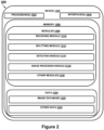
- the device 102 includes at least one processor 202, an input/output (I/O) interface 204, and a memory 206.
- the at least one processor 202 is implemented as one or more microprocessors, microcomputers, microcontrollers, digital signal processors, central processing units, state machines, logic circuitries, and/or any devices that manipulate signals based on operational instructions.
- the at least one processor 202 is configured to fetch and execute computer-readable instructions or modules stored in the memory 206.
- the I/O interface 204 includes a variety of software and hardware interfaces, for example, a web interface, a graphical user interface, and the like.
- the I/O interface 204 allows the device 102 to interact with a user directly or through the client devices 104. Further, the I/O interface 204 enables the device 102 to communicate with other computing devices, such as web servers and external data servers (not shown).
- the I/O interface 204 facilitates multiple communications within a wide variety of networks and protocol types, including wired networks, for example, LAN, cable, etc., and wireless networks, such as WLAN, cellular, or satellite.
- the I/O interface 204 includes one or more ports for connecting a number of devices to one another or to another server.
- the memory 206 includes any computer-readable medium or computer program product known in the art including, for example, volatile memory, such as static random access memory (SRAM) and dynamic random access memory (DRAM), and/or non-volatile memory, such as read only memory (ROM), erasable programmable ROM, flash memories, hard disks, optical disks, a compact disks (CDs), digital versatile disc or digital video disc (DVDs) and magnetic tapes.
- volatile memory such as static random access memory (SRAM) and dynamic random access memory (DRAM)
- non-volatile memory such as read only memory (ROM), erasable programmable ROM, flash memories, hard disks, optical disks, a compact disks (CDs), digital versatile disc or digital video disc (DVDs) and magnetic tapes.
- ROM read only memory
- ROM erasable programmable ROM
- flash memories such as compact disks (CDs), digital versatile disc or digital video disc (DVDs) and magnetic tapes.
- CDs compact disks
- the modules 208 include routines, programs, objects, components, data structures, etc., which perform particular tasks or implement particular abstract data types.
- the modules 208 includes a receiving module 210, a splitting module 212, detecting module 214, an image processing module 216, and other modules 218.
- the other modules 218 includes programs or coded instructions that supplement applications and functions of the device 102.
- the data 220 serves as a repository for storing data processed, received, and generated by one or more of the modules 208.
- the data 220 also includes an image database 222, and other data 224.
- FIG. 1 a four-wheeler vehicle is shown ( Fig. 1 ) i.e., vehicle 110.
- the device 102 is provided for detecting objects at a near and far distance (i.e., multiple ranges) from the vehicle 110 in order to avoid collision of the vehicle 110 with the object. While the vehicle 110 is in the motion, it is extremely important to accurately detect the objects in the path of the vehicle 110. The objects appear at near as well as far distance from the vehicle 110. Further, the objects is in a still or a moving position.
- object 1 is placed at a far distance and object 2 is placed at near distance from the vehicle 110 as shown in figure 3 .
- the device 102 of the present disclosure facilitates a simultaneous detection of the objects at the near and the far distance from the vehicle 110.
- the far distance ranges up to 80 meters
- the near distance ranges up to 5 meters. It must be noted to a person skilled in art that the ranges corresponding to near and far distance from the vehicle 110 varies and the present disclosure is not limited to aforementioned ranges of the far distance and the near distance.
- an image of the object 1 and the object 2 is captured by an image capturing unit 108 of the vehicle 110.
- the image capturing unit 108 is a mono or stereo type camera (pair of imagers) used for capturing the images of one or more objects placed at the near and the far distance from the vehicle 110.
- the images captured is stored in an image database 220 of the device 102.
- the receiving module 210 of the device 102 receives the image corresponding to the objects appearing on the path of the vehicle 110.
- the splitting module 212 of the device 102 splits the image received into a plurality of sub-images/slices indicating region of interest (ROIs).
- ROIs region of interest
- each sub-image of the plurality of sub-images is in a form of rectangular windows of pixels computed based on distance of the detection (i.e., distance between the objects and the vehicle 110). Since the objects looks bigger in short distance range and smaller in long distance range, there is a big rectangular window corresponding to short range of distance, and a smaller rectangular window corresponding to long range of distance.
- a range for the region of interest (ROI) is defined such that a sub-image located at a distance up to 20 meters, 50 meters 80 meters, from the vehicle 110, is sliced into ROI1, ROI2, and ROI3 respectively.
- the above example of the range defined for the ROIs is applicable for VGA type camera. It is to be noted to a person skilled in art that, the distance of detection (i.e., ranges defined for ROIs) improves with resolution of the camera and further the ROI selection varies accordingly.
- the image processing module 216 of the device 102 enlarges one or more sub-images of the plurality of sub-images based on the distance of the near object and the far object from the vehicle.
- the one or more sub-images are enlarged in size by using a bilinear interpolation method to 2x times the original of the ROI2, and is 3x times the original of the ROI3.
- the image processing module 216 applies erosion followed by dilation upon the interpolated one or more sub-images.
- the application of the erosion and the dilation results in reduction in a noise of the one or more sub-images, isolation of individual elements, and joining of disconnected parts in the one or more sub-images.
- the dilation involves convoluting of the one or more sub-images with a kernel which is a circle.
- the kernel is scanned over the one or more sub-images and finds the maximum pixel value overlapped by the kernel and replaces the pixel value with the maximum pixel value.
- the dilation does the opposite of this as it tries to find local minimum over the area of kernel. With this the bright areas in the one or more sub-images gets thinner whereas the dark areas get thicker.
- the image processing module 216 Upon applying the erosion and the dilation, the image processing module 216 further sharpens the one or more sub-images with a two dimensional image sharpening filter with a median of 3x3 kernels. This step helps in sharpening the edges while removing the noise from the one or more sub-images.
- the image processing module 216 is further configured for smoothening the one or more sub-images using a two dimensional smoothening filters with 3x3 Gaussian kernel.
- the Gaussian kernel helps in reducing the blur from the one or more sub-images which is introduced due to motion of the image capturing unit 108.
- the detecting module 214 of the device 102 detects a near object and a far object from the plurality of sub-images by extracting one or more features from the plurality of sub-images.
- the detecting module 214 further simultaneously processes each of the plurality of sub-images for computing gradient associated with the each of the plurality of sub-images based on the one or more features extracted.
- three different window sizes is processed simultaneously for computing the gradient associated with three different ROIs (ROI1, ROI2, and ROI3).
- a one dimensional derivate mask is scanned in both horizontal and vertical directions. Further, the intensity channel of the image data is filtered using the following kernel: ⁇ 1 , 0,1 and ⁇ 1 , 0,1 T .
- the detecting module 214 creates cell histograms by casting a weighted vote for an orientation based histogram channel based on the values associated with the gradient computed.
- the cell histograms comprises plurality of cells rectangular in shape and the histogram of channels are spaced over 180 degrees with unsigned gradient with nine histogram channels.
- the detecting module 214 of the device 102 normalizes the gradient strengths in order to reduce the effect of changes in illumination and contrast.
- the cells of the plurality of cells is grouped in spatial blocks.
- gradient value is divided into window size which is specific to the ROI.
- 128 x 64 is used and gradient values is divided into 16 ⁇ 16 pixel block which in turn contains 4 cells of 8x8 pixels and each such cell in turn contain 9 histogram bin values. So finally 36 weighted bin values are computed which gets multiplied with 105 blocks creating 3780 descriptor values.
- the detecting module 214 significantly improves the speed of processing than the traditional way of computing the gradient for each window separately Further, by processing the three different window sizes simultaneously for computing the gradient associated with the three different ROIs, a concept of an enhanced histogram of oriented gradients (EHOG) is disclosed as per the present disclosure.
- EHOG overcomes the limitation of Histogram of Oriented Gradients (HOG) i.e., processing only one window size at a time by processing the three different window sizes simultaneously.
- the detecting module 214 of the device 102 applies a Support Vector Machine (SVM) linear classifier on the plurality of sub-images in order to classify the near object and the far object in a category of a pedestrian or a vehicle.
- SVM Support Vector Machine
- a SVM learning is performed on samples containing images of objects of interest (for eg: vehicles) cropped to the size of the window sizes as discussed above.
- the detecting module 214 uses following formulae for efficiently classifying the one or more objects images simultaneously with each of the window size and each of the ROI.
- Xi is the feature vector of Histogram of Oriented Gradients (HOG)
- Yi is the feature vector of SVM trained data
- N number of samples per block
- M1 is the number of blocks per window for 128x64
- M2 64x64 and M3 for 32x32 windows.
- the SVM trained data comprises predefined features associated with the objects categorized into predefined categories.
- the SVM classifier compares the one or more features of the objects with the predefined features of the SVM trained data. Based on the comparison, the objects are detected as the near and the far object as well as the objects are categorized into the category.
- 3 different scale windows are simultaneously processed for classification, it ensures multi scale classification of objects into the category (eg: pedestrian, vehicle) without major overhead on the computational complexity.
- the objects are classified into other categories (other than pedestrian or vehicle) based on the predefined features of the SVM trained data.
- the predefined features for the category "pedestrian” are hands, eyes, legs and the like.
- the predefined features for the category "vehicle” are number plate, wheels, steering and the like.
- the method 400 is described in the general context of computer executable instructions.
- computer executable instructions includes routines, programs, objects, components, data structures, procedures, modules, functions, etc., that perform particular functions or implement particular abstract data types.
- the method 400 is also be practiced in a distributed computing environment where functions are performed by remote processing devices that are linked through a communications network.
- computer executable instructions are located in both local and remote computer storage media, including memory storage devices
- the order in which the method 400 is described is not intended to be construed as a limitation, and any number of the described method blocks is combined in any order to implement the method 400 or alternate methods.
- the method is implemented in any suitable hardware, software, firmware, or combination thereof.
- the method 400 is considered to be implemented in the above described device 102.
- image corresponding to objects appearing on the path of the vehicle is received.
- the image received is captured by an image capturing unit installed on the vehicle.
- the image received is split into plurality of sub-images indicating region of interest (ROIs). Further, each of the plurality of sub-images is in a form of a rectangular window of pixels computed based on distance of the objects from the vehicle.
- the plurality of sub-images is further processed for reducing the noise from the images, isolating the individual elements from the images, joining the disconnected parts of the images, sharpening the edges of the images, and further smoothening the images using smoothening filters.
- the near and far object from the plurality of sub-images is detected performing the steps shown in blocks 406A-406E.
- one or more features is extracted from the plurality of sub-images.
- each of the plurality of sub-images is simultaneously processed for computing gradient associated with each of the plurality of sub-images based on the one or more features extracted.
- cell histograms comprising plurality of cells is created by casting weighted vote for an orientation based histogram channel based on values associated with the gradient.
- the gradients computed is normalized by grouping the cells of the plurality of cells in spatial blocks in order to normalize the plurality of sub-images.
- a Support vector Machine (SVM) linear classifier is applied on the plurality of sub-images after being normalized in order to detect and classify the near object and the far object in a category.
- SVM Support vector Machine
Landscapes
- Engineering & Computer Science (AREA)
- Theoretical Computer Science (AREA)
- Physics & Mathematics (AREA)
- General Physics & Mathematics (AREA)
- Multimedia (AREA)
- Computer Vision & Pattern Recognition (AREA)
- Data Mining & Analysis (AREA)
- Bioinformatics & Cheminformatics (AREA)
- Evolutionary Computation (AREA)
- Evolutionary Biology (AREA)
- General Engineering & Computer Science (AREA)
- Bioinformatics & Computational Biology (AREA)
- Artificial Intelligence (AREA)
- Life Sciences & Earth Sciences (AREA)
- Image Analysis (AREA)
- Traffic Control Systems (AREA)
Claims (11)
- Verfahren zum gleichzeitigen Erfassen von Objekten in mehreren Entfernungen auf einem Weg eines Fahrzeugs, wobei das Verfahren Folgendes umfasst:Empfangen, durch einen Prozessor, eines Bildes als Eingabe, das Objekten entspricht, die auf dem Weg des Fahrzeugs erscheinen Aufteilen des Bildes durch den Prozessor in eine Vielzahl von Teilbildern, die einen interessierenden Bereich (ROI) anzeigen, wobei jedes der Vielzahl von Teilbildern in Form eines rechteckigen Fensters von Pixeln vorliegt, das auf der Grundlage des Abstands der Objekte von dem Fahrzeug berechnet wird, wobei der Abstand der Objekte von dem Fahrzeug auf der Grundlage der Auflösung der mindestens einen Bilderfassungseinheit erfasst wird, und wobei ein großes rechteckiges Fenster von Pixeln anzeigt, dass sich die Objekte in einem kurzen Abstand von dem Fahrzeug befinden, und ein kleines rechteckiges Fenster von Pixeln anzeigt, dass sich die Objekte in einem großen Abstand von dem Fahrzeug befinden; undErfassen eines ersten Objekts und eines zweiten Objekts in unterschiedlichen Entfernungen aus der Vielzahl von Teilbildern durch den Prozessor, indem ein oder mehrere Merkmale aus der Vielzahl von Teilbildern extrahiert werden;gleichzeitiges Verarbeiten jedes der Vielzahl von Teilbildern zum Berechnen eines Gradienten, der mit jedem der Vielzahl von Teilbildern verbunden ist, basierend auf dem einen oder den mehreren extrahierten Merkmalen,wobei das Verarbeiten jedes der Vielzahl von Teilbildern Folgendes umfasst:Interpolieren des einen oder der mehreren Teilbilder auf der Grundlage des Abstands des ersten Objekts und des zweiten Objekts von dem Fahrzeug,wobei die Interpolation des einen oder der mehreren Teilbilder eine Vergrößerung des einen oder der mehreren Teilbilder unter Verwendung einer bilinearen Interpolationstechnik umfasst; undAnwenden von Erosion und Dilatation auf das eine oder die mehreren Teilbilder, um Rauschen von dem einen oder den mehreren Teilbildern zu reduzieren, Isolieren einzelner Elemente des einen oder der mehreren Teilbilder und Verbinden von nicht verbundenen Teilen in dem einen oder den mehreren Teilbildern,Erzeugen von Zellenhistogrammen, die eine Vielzahl von Zellen umfassen, durch Abgabe einer gewichteten Stimme für einen orientierungsbasierten Histogrammkanal auf der Grundlage von Werten, die mit dem berechneten Gradienten verbunden sind,Normalisieren der berechneten Gradienten durch Gruppieren der Zellen der Vielzahl von Zellen in räumlichen Blöcken, um die Vielzahl von Teilbildern zu normalisieren; undAnwenden eines linearen Klassifizierers mit Stützvektor-Maschine (SVM) auf die Vielzahl von Unterbildern, nachdem sie normalisiert wurden, um das erste Objekt und das zweite Objekt in einer Kategorie zu erkennen und zu klassifizieren.
- Verfahren nach Anspruch 1, wobei das Bild von einer oder mehreren Bildaufnahmeeinheiten des Fahrzeugs aufgenommen wird.
- Verfahren nach Anspruch 1, wobei sich das erste Objekt und das zweite Objekt in einer Entfernung von X Metern bzw. N-X Metern, auf einer Skala von 0 bis N Metern, vom Fahrzeug befinden.
- Verfahren nach Anspruch 1, wobei jedes Teilbild der Vielzahl von Teilbildern in einer spezifischen ROI auf der Grundlage eines vordefinierten Abstandsbereichs der Objekte zum Fahrzeug definiert ist.
- Verfahren nach Anspruch 1, wobei der lineare SVM-Klassifikator die Objekte anhand einer Formel in die Kategorie einordnet:

- Verfahren nach Anspruch 1, wobei die Vielzahl von Teilbildern weiter verarbeitet wird durchSchärfen des einen oder der mehreren Teilbilder unter Verwendung eines zweidimensionalen Bildschärfungsfilters mit einem Median von 3x3 Kernen; undGlätten des einen oder der mehreren Teilbilder unter Verwendung von zweidimensionalen Glättungsfiltern mit einem 3X3-Gauß-Kernel.
- Vorrichtung (102) zum gleichzeitigen Erfassen von Objekten in mehreren Entfernungen auf einem Weg eines Fahrzeugs, wobei die Vorrichtung (102) Folgendes umfasst:einen Prozessor (202);einen Speicher (206), der mit dem Prozessor (202) gekoppelt ist, wobei der Prozessor (202) eine Vielzahl von Modulen (208) ausführt, die in dem Speicher (206) gespeichert sind, und wobei die Vielzahl von Modulen (208) umfasst:ein Empfangsmodul (210) zum Empfangen eines Bildes als eine Eingabe, die Objekten entspricht, die auf dem Weg des Fahrzeugs erscheinen;ein Aufteilungsmodul (212), um das Bild in eine Vielzahl von Unterbildern aufzuteilen, die einen interessierenden Bereich (ROI) anzeigen, wobei jedes der Vielzahl von Unterbildern in Form eines rechteckigen Fensters von Pixeln vorliegt, das auf der Grundlage des Abstands der Objekte vom Fahrzeug berechnet wird,wobei der Abstand der Objekte von dem Fahrzeug basierend auf der Auflösung der mindestens einen Bilderfassungseinheit erfasst wird, und wobei ein großes rechteckiges Fenster von Pixeln anzeigt, dass die Objekte in einem kurzen Abstand von dem Fahrzeug sind, und ein kleines rechteckiges Fenster von Pixeln anzeigt, dass die Objekte in einem großen Abstand von dem Fahrzeug sind; undein Erfassungsmodul (214) zum Erfassen eines ersten Objekts und eines zweiten Objekts in unterschiedlichen Entfernungen aus der Vielzahl von Teilbildern durch:Extrahieren eines oder mehrerer Merkmale aus der Vielzahl von Teilbildern; gleichzeitiges Verarbeiten jedes der Vielzahl von Teilbildern zum Berechnen eines Gradienten, der mit jedem der Vielzahl von Teilbildern verbunden ist, basierend auf dem einen oder den mehreren extrahierten Merkmalen, wobei das Verarbeiten jedes der Vielzahl von Teilbildern umfasst Interpolieren des einen oder der mehreren Teilbilder auf der Grundlage des Abstands des ersten Objekts und des zweiten Objekts von dem Fahrzeug, wobei die Interpolation des einen oder der mehreren Teilbilder die Vergrößerung des einen oder der mehreren Teilbilder unter Verwendung einer bilinearen Interpolationstechnik umfasst; undAnwenden von Erosion und Dilatation auf das eine oder die mehreren Teilbilder, um Rauschen von dem einen oder den mehreren Teilbildern zu reduzieren, Isolieren einzelner Elemente des einen oder der mehreren Teilbilder und Verbinden von nicht verbundenen Teilen in dem einen oder den mehreren Teilbildern;Erzeugen von Zellenhistogrammen, die eine Vielzahl von Zellen umfassen, durch Abgabe einer gewichteten Stimme für einen orientierungsbasierten Histogrammkanal auf der Grundlage von Werten, die mit dem berechneten Gradienten verbunden sind,Normalisieren der berechneten Gradienten durch Gruppieren der Zellen der Vielzahl von Zellen in räumlichen Blöcken, um die Vielzahl von Teilbildern zu normalisieren; undAnwenden eines linearen Klassifizierers mit Stützvektor-Maschine (SVM) auf die Vielzahl von Unterbildern, nachdem sie normalisiert wurden, um das erste Objekt und das zweite Objekt in einer Kategorie zu erkennen und zu klassifizieren.
- Vorrichtung (102) nach Anspruch 7, wobei das Bild von einer oder mehreren Bildaufnahmeeinheiten des Fahrzeugs aufgenommen wird.
- Vorrichtung (102) nach Anspruch 7, wobei sich das erste Objekt und das zweite Objekt in einer Entfernung von X Metern bzw. N-X Metern, auf einer Skala von 0 bis N Metern, vom Fahrzeug befinden.
- Vorrichtung (102) nach Anspruch 7, wobei jedes Teilbild der Vielzahl von Teilbildern in einer spezifischen ROI definiert ist, die auf einem vordefinierten Entfernungsbereich der Objekte vom Fahrzeug basiert, wobei die Entfernung des Objekts bis zu 20 Metern unter ROI1 fällt.
- Vorrichtung (102) nach Anspruch 7, umfassend ferner ein Bildverarbeitungsmodul (216) zum Verarbeiten der Vielzahl von Teilbildern durch:Schärfen des einen oder der mehreren Teilbilder unter Verwendung eines zweidimensionalen Bildschärfungsfilters mit einem Median von 3x3 Kernen; undGlätten des einen oder der mehreren Teilbilder unter Verwendung zweidimensionaler Glättungsfilter mit 3X3 Gauß-Kernen.
Applications Claiming Priority (1)
| Application Number | Priority Date | Filing Date | Title |
|---|---|---|---|
| IN794MU2014 | 2014-03-07 |
Publications (3)
| Publication Number | Publication Date |
|---|---|
| EP2916264A1 EP2916264A1 (de) | 2015-09-09 |
| EP2916264C0 EP2916264C0 (de) | 2025-03-05 |
| EP2916264B1 true EP2916264B1 (de) | 2025-03-05 |
Family
ID=52780369
Family Applications (1)
| Application Number | Title | Priority Date | Filing Date |
|---|---|---|---|
| EP15158136.0A Active EP2916264B1 (de) | 2014-03-07 | 2015-03-09 | Mehrbereichs-objekterkennungsvorrichtung und verfahren |
Country Status (3)
| Country | Link |
|---|---|
| US (1) | US9542625B2 (de) |
| EP (1) | EP2916264B1 (de) |
| JP (1) | JP5982026B2 (de) |
Families Citing this family (13)
| Publication number | Priority date | Publication date | Assignee | Title |
|---|---|---|---|---|
| CN104864849B (zh) * | 2014-02-24 | 2017-12-26 | 电信科学技术研究院 | 视觉导航方法和装置以及机器人 |
| CN105447448B (zh) * | 2015-11-12 | 2019-01-11 | 江南大学 | 一种基于高斯颜色距离的卡口车辆定位方法 |
| JP6705497B2 (ja) * | 2016-02-23 | 2020-06-03 | 株式会社リコー | 画像処理装置、撮像装置、移動体機器制御システム、画像処理方法、プログラム、及び移動体 |
| US11107229B2 (en) | 2018-01-10 | 2021-08-31 | Samsung Electronics Co., Ltd. | Image processing method and apparatus |
| CN108875537B (zh) * | 2018-02-28 | 2022-11-08 | 北京旷视科技有限公司 | 对象检测方法、装置和系统及存储介质 |
| CN108681707A (zh) * | 2018-05-15 | 2018-10-19 | 桂林电子科技大学 | 基于全局和局部特征融合的大角度车型识别方法和系统 |
| EP3584742A1 (de) * | 2018-06-19 | 2019-12-25 | KPIT Technologies Ltd. | Systeme und verfahren zur verkehrsschilderkennung |
| CN110458227B (zh) * | 2019-08-08 | 2021-11-23 | 杭州电子科技大学 | 一种基于混合分类器的adas行人检测方法 |
| CN110866435B (zh) * | 2019-08-13 | 2023-09-12 | 广州三木智能科技有限公司 | 一种自相似性梯度朝向直方图的远红外行人训练方法 |
| CN111127459B (zh) * | 2019-12-30 | 2023-05-26 | 武汉理工大学 | 路面车辙检测的图像实时处理系统 |
| CN113506264B (zh) * | 2021-07-07 | 2023-08-29 | 北京航空航天大学 | 道路车辆数识别方法和装置 |
| KR102587693B1 (ko) * | 2021-10-08 | 2023-10-12 | 주식회사 디알엠인사이드 | 이미지 저작권 보호를 위한 이미지 식별 장치 및 이의 동작 방법 |
| CN113627416B (zh) * | 2021-10-12 | 2022-01-25 | 上海蜜度信息技术有限公司 | 图片分类和对象检测的同步处理方法、系统、存储介质及终端 |
Family Cites Families (12)
| Publication number | Priority date | Publication date | Assignee | Title |
|---|---|---|---|---|
| JP3716057B2 (ja) * | 1996-08-30 | 2005-11-16 | 綜合警備保障株式会社 | 人物検知用画像処理方法 |
| JP2008203992A (ja) * | 2007-02-16 | 2008-09-04 | Omron Corp | 検出装置および方法、並びに、プログラム |
| CN101872477B (zh) | 2009-04-24 | 2014-07-16 | 索尼株式会社 | 检测图像中的对象的方法、装置,及包括该装置的系统 |
| JP5272886B2 (ja) | 2009-05-14 | 2013-08-28 | ソニー株式会社 | 動体検出装置と動体検出方法およびコンピュータ・プログラム |
| JP5361530B2 (ja) * | 2009-05-20 | 2013-12-04 | キヤノン株式会社 | 画像認識装置、撮像装置及び画像認識方法 |
| JP2010282388A (ja) * | 2009-06-04 | 2010-12-16 | Mazda Motor Corp | 車両用歩行者検出装置 |
| JP5598694B2 (ja) * | 2009-08-25 | 2014-10-01 | スズキ株式会社 | 物標検出装置および物標検出方法 |
| US8861842B2 (en) * | 2010-02-05 | 2014-10-14 | Sri International | Method and apparatus for real-time pedestrian detection for urban driving |
| JP2013029933A (ja) * | 2011-07-27 | 2013-02-07 | Suzuki Motor Corp | パターン認識装置 |
| CN103366177B (zh) * | 2012-03-28 | 2016-12-07 | 佳能株式会社 | 对象检测分类器生成方法和设备、图像对象检测方法和设备 |
| JP5648655B2 (ja) * | 2012-04-27 | 2015-01-07 | 株式会社デンソー | 対象物識別装置 |
| CN103268363B (zh) | 2013-06-06 | 2016-06-22 | 哈尔滨工业大学 | 一种基于弹性hog特征和ddtw匹配的中国书法图像检索方法 |
-
2015
- 2015-03-09 EP EP15158136.0A patent/EP2916264B1/de active Active
- 2015-03-09 JP JP2015045865A patent/JP5982026B2/ja active Active
- 2015-03-09 US US14/642,269 patent/US9542625B2/en active Active
Also Published As
| Publication number | Publication date |
|---|---|
| JP5982026B2 (ja) | 2016-08-31 |
| US20150254531A1 (en) | 2015-09-10 |
| EP2916264A1 (de) | 2015-09-09 |
| JP2015187855A (ja) | 2015-10-29 |
| EP2916264C0 (de) | 2025-03-05 |
| US9542625B2 (en) | 2017-01-10 |
Similar Documents
| Publication | Publication Date | Title |
|---|---|---|
| US9542625B2 (en) | Multi range object detection device and method | |
| US10503999B2 (en) | System for detecting salient objects in images | |
| US9008365B2 (en) | Systems and methods for pedestrian detection in images | |
| US20200364481A1 (en) | Image processing | |
| Chuang et al. | Estimating gaze direction of vehicle drivers using a smartphone camera | |
| US10963676B2 (en) | Image processing method and apparatus | |
| EP3168810A1 (de) | Bilderzeugungsverfahren und -vorrichtung | |
| US9530079B2 (en) | Point spread function classification using structural properties | |
| KR101848019B1 (ko) | 차량 영역 검출을 통한 차량 번호판 검출 방법 및 장치 | |
| US11138446B2 (en) | Apparatus and method for detecting object of a vehicle | |
| US20090110286A1 (en) | Detection method | |
| Wu et al. | Raindrop detection and removal using salient visual features | |
| Romera et al. | A Real-Time Multi-scale Vehicle Detection and Tracking Approach for Smartphones. | |
| Gluhaković et al. | Vehicle detection in the autonomous vehicle environment for potential collision warning | |
| EP3951703B1 (de) | Verfahren und vorrichtung mit bildverarbeitung | |
| US20130300897A1 (en) | Image processing device, image processing method, and image processing program | |
| US20200356801A1 (en) | Method and device for object detection | |
| Webster et al. | Improved raindrop detection using combined shape and saliency descriptors with scene context isolation | |
| Jaskó et al. | Animal detection from traffic scenarios based on monocular color vision | |
| EP3635631B1 (de) | System zur detektion von auffälligen objekten in bildern | |
| Tasson et al. | FPGA-based pedestrian detection under strong distortions | |
| Kurnianggoro et al. | Visual perception of traffic sign for autonomous vehicle using k-nearest cluster neighbor classifier | |
| CN111950502B (zh) | 基于障碍对象的检测方法、装置及计算机设备 | |
| Fuad et al. | A novel traffic system for detecting lane-based rule violation | |
| Lee et al. | On-road vehicle detection based on appearance features for autonomous vehicles |
Legal Events
| Date | Code | Title | Description |
|---|---|---|---|
| PUAI | Public reference made under article 153(3) epc to a published international application that has entered the european phase |
Free format text: ORIGINAL CODE: 0009012 |
|
| AK | Designated contracting states |
Kind code of ref document: A1 Designated state(s): AL AT BE BG CH CY CZ DE DK EE ES FI FR GB GR HR HU IE IS IT LI LT LU LV MC MK MT NL NO PL PT RO RS SE SI SK SM TR |
|
| AX | Request for extension of the european patent |
Extension state: BA ME |
|
| 17P | Request for examination filed |
Effective date: 20160308 |
|
| RBV | Designated contracting states (corrected) |
Designated state(s): AL AT BE BG CH CY CZ DE DK EE ES FI FR GB GR HR HU IE IS IT LI LT LU LV MC MK MT NL NO PL PT RO RS SE SI SK SM TR |
|
| STAA | Information on the status of an ep patent application or granted ep patent |
Free format text: STATUS: EXAMINATION IS IN PROGRESS |
|
| 17Q | First examination report despatched |
Effective date: 20180222 |
|
| REG | Reference to a national code |
Ref country code: DE Ref legal event code: R079 Free format text: PREVIOUS MAIN CLASS: G06K0009000000 Ipc: G06V0010400000 Ref country code: DE Ref legal event code: R079 Ref document number: 602015091143 Country of ref document: DE Free format text: PREVIOUS MAIN CLASS: G06K0009000000 Ipc: G06V0010400000 |
|
| GRAP | Despatch of communication of intention to grant a patent |
Free format text: ORIGINAL CODE: EPIDOSNIGR1 |
|
| STAA | Information on the status of an ep patent application or granted ep patent |
Free format text: STATUS: GRANT OF PATENT IS INTENDED |
|
| RIC1 | Information provided on ipc code assigned before grant |
Ipc: G06V 20/56 20220101ALI20241021BHEP Ipc: G06V 10/40 20220101AFI20241021BHEP |
|
| INTG | Intention to grant announced |
Effective date: 20241104 |
|
| GRAS | Grant fee paid |
Free format text: ORIGINAL CODE: EPIDOSNIGR3 |
|
| GRAA | (expected) grant |
Free format text: ORIGINAL CODE: 0009210 |
|
| STAA | Information on the status of an ep patent application or granted ep patent |
Free format text: STATUS: THE PATENT HAS BEEN GRANTED |
|
| AK | Designated contracting states |
Kind code of ref document: B1 Designated state(s): AL AT BE BG CH CY CZ DE DK EE ES FI FR GB GR HR HU IE IS IT LI LT LU LV MC MK MT NL NO PL PT RO RS SE SI SK SM TR |
|
| REG | Reference to a national code |
Ref country code: GB Ref legal event code: FG4D |
|
| REG | Reference to a national code |
Ref country code: CH Ref legal event code: EP |
|
| REG | Reference to a national code |
Ref country code: IE Ref legal event code: FG4D |
|
| REG | Reference to a national code |
Ref country code: DE Ref legal event code: R096 Ref document number: 602015091143 Country of ref document: DE |
|
| RAP4 | Party data changed (patent owner data changed or rights of a patent transferred) |
Owner name: TATA CONSULTANCY SERVICES LIMITED |
|
| U01 | Request for unitary effect filed |
Effective date: 20250403 |
|
| RAP4 | Party data changed (patent owner data changed or rights of a patent transferred) |
Owner name: TATA CONSULTANCY SERVICES LIMITED |
|
| U07 | Unitary effect registered |
Designated state(s): AT BE BG DE DK EE FI FR IT LT LU LV MT NL PT RO SE SI Effective date: 20250411 |
|
| PG25 | Lapsed in a contracting state [announced via postgrant information from national office to epo] |
Ref country code: RS Free format text: LAPSE BECAUSE OF FAILURE TO SUBMIT A TRANSLATION OF THE DESCRIPTION OR TO PAY THE FEE WITHIN THE PRESCRIBED TIME-LIMIT Effective date: 20250605 |
|
| PG25 | Lapsed in a contracting state [announced via postgrant information from national office to epo] |
Ref country code: ES Free format text: LAPSE BECAUSE OF FAILURE TO SUBMIT A TRANSLATION OF THE DESCRIPTION OR TO PAY THE FEE WITHIN THE PRESCRIBED TIME-LIMIT Effective date: 20250305 |
|
| PG25 | Lapsed in a contracting state [announced via postgrant information from national office to epo] |
Ref country code: NO Free format text: LAPSE BECAUSE OF FAILURE TO SUBMIT A TRANSLATION OF THE DESCRIPTION OR TO PAY THE FEE WITHIN THE PRESCRIBED TIME-LIMIT Effective date: 20250605 |
|
| PG25 | Lapsed in a contracting state [announced via postgrant information from national office to epo] |
Ref country code: HR Free format text: LAPSE BECAUSE OF FAILURE TO SUBMIT A TRANSLATION OF THE DESCRIPTION OR TO PAY THE FEE WITHIN THE PRESCRIBED TIME-LIMIT Effective date: 20250305 |
|
| PG25 | Lapsed in a contracting state [announced via postgrant information from national office to epo] |
Ref country code: GR Free format text: LAPSE BECAUSE OF FAILURE TO SUBMIT A TRANSLATION OF THE DESCRIPTION OR TO PAY THE FEE WITHIN THE PRESCRIBED TIME-LIMIT Effective date: 20250606 |
|
| PG25 | Lapsed in a contracting state [announced via postgrant information from national office to epo] |
Ref country code: SM Free format text: LAPSE BECAUSE OF FAILURE TO SUBMIT A TRANSLATION OF THE DESCRIPTION OR TO PAY THE FEE WITHIN THE PRESCRIBED TIME-LIMIT Effective date: 20250305 |
|
| PG25 | Lapsed in a contracting state [announced via postgrant information from national office to epo] |
Ref country code: PL Free format text: LAPSE BECAUSE OF FAILURE TO SUBMIT A TRANSLATION OF THE DESCRIPTION OR TO PAY THE FEE WITHIN THE PRESCRIBED TIME-LIMIT Effective date: 20250305 |
|
| PG25 | Lapsed in a contracting state [announced via postgrant information from national office to epo] |
Ref country code: CZ Free format text: LAPSE BECAUSE OF FAILURE TO SUBMIT A TRANSLATION OF THE DESCRIPTION OR TO PAY THE FEE WITHIN THE PRESCRIBED TIME-LIMIT Effective date: 20250305 |
|
| REG | Reference to a national code |
Ref country code: CH Ref legal event code: H13 Free format text: ST27 STATUS EVENT CODE: U-0-0-H10-H13 (AS PROVIDED BY THE NATIONAL OFFICE) Effective date: 20251024 |
|
| PG25 | Lapsed in a contracting state [announced via postgrant information from national office to epo] |
Ref country code: SK Free format text: LAPSE BECAUSE OF FAILURE TO SUBMIT A TRANSLATION OF THE DESCRIPTION OR TO PAY THE FEE WITHIN THE PRESCRIBED TIME-LIMIT Effective date: 20250305 |
|
| PG25 | Lapsed in a contracting state [announced via postgrant information from national office to epo] |
Ref country code: IS Free format text: LAPSE BECAUSE OF FAILURE TO SUBMIT A TRANSLATION OF THE DESCRIPTION OR TO PAY THE FEE WITHIN THE PRESCRIBED TIME-LIMIT Effective date: 20250705 |
|
| U90 | Renewal fees not paid: noting of loss of rights |
Free format text: RENEWAL FEE NOT PAID FOR YEAR 11 Effective date: 20251022 |
|
| PG25 | Lapsed in a contracting state [announced via postgrant information from national office to epo] |
Ref country code: MC Free format text: LAPSE BECAUSE OF FAILURE TO SUBMIT A TRANSLATION OF THE DESCRIPTION OR TO PAY THE FEE WITHIN THE PRESCRIBED TIME-LIMIT Effective date: 20250305 |
|
| PLBE | No opposition filed within time limit |
Free format text: ORIGINAL CODE: 0009261 |
|
| STAA | Information on the status of an ep patent application or granted ep patent |
Free format text: STATUS: NO OPPOSITION FILED WITHIN TIME LIMIT |
|
| REG | Reference to a national code |
Ref country code: CH Ref legal event code: L10 Free format text: ST27 STATUS EVENT CODE: U-0-0-L10-L00 (AS PROVIDED BY THE NATIONAL OFFICE) Effective date: 20260114 |
|
| PG25 | Lapsed in a contracting state [announced via postgrant information from national office to epo] |
Ref country code: CH Free format text: LAPSE BECAUSE OF NON-PAYMENT OF DUE FEES Effective date: 20250331 |
|
| PG25 | Lapsed in a contracting state [announced via postgrant information from national office to epo] |
Ref country code: IE Free format text: LAPSE BECAUSE OF NON-PAYMENT OF DUE FEES Effective date: 20250309 |
|
| 26N | No opposition filed |
Effective date: 20251208 |
|
| U93 | Unitary patent lapsed |
Free format text: RENEWAL FEE NOT PAID Effective date: 20250331 |
|
| GBPC | Gb: european patent ceased through non-payment of renewal fee |
Effective date: 20250605 |
|
| PG25 | Lapsed in a contracting state [announced via postgrant information from national office to epo] |
Ref country code: GB Free format text: LAPSE BECAUSE OF NON-PAYMENT OF DUE FEES Effective date: 20250605 |