EP2916409A2 - Cadre pour passe-câble, éléments de fixation et système de passe-câble - Google Patents
Cadre pour passe-câble, éléments de fixation et système de passe-câble Download PDFInfo
- Publication number
- EP2916409A2 EP2916409A2 EP15156718.7A EP15156718A EP2916409A2 EP 2916409 A2 EP2916409 A2 EP 2916409A2 EP 15156718 A EP15156718 A EP 15156718A EP 2916409 A2 EP2916409 A2 EP 2916409A2
- Authority
- EP
- European Patent Office
- Prior art keywords
- frame
- recess
- lever
- projection
- cable
- Prior art date
- Legal status (The legal status is an assumption and is not a legal conclusion. Google has not performed a legal analysis and makes no representation as to the accuracy of the status listed.)
- Withdrawn
Links
Images


Classifications
-
- H—ELECTRICITY
- H02—GENERATION; CONVERSION OR DISTRIBUTION OF ELECTRIC POWER
- H02G—INSTALLATION OF ELECTRIC CABLES OR LINES, OR OF COMBINED OPTICAL AND ELECTRIC CABLES OR LINES
- H02G3/00—Installations of electric cables or lines or protective tubing therefor in or on buildings, equivalent structures or vehicles
- H02G3/22—Installations of cables or lines through walls, floors or ceilings, e.g. into buildings
Definitions
- the invention relates to a frame for cable penetrations, fasteners and a cable feedthrough system.
- Cable gland systems are used for the safe passage of cables through the walls of enclosures or control cabinets.
- modular cable glands are known in which various cable grommets can be clamped in an interchangeable frame.
- the cable grommets are inserted into a frame, which is then closed.
- a frame for cable ducts with two frame parts, a mounting for fastening elements and two lever systems, wherein the frame parts have contact surfaces which limit the receptacle, wherein each lever system is arranged at one end of a frame part and in each case an actuating lever and a clamping lever has, which are pivotally connected to each other, wherein the actuating lever is pivotally mounted on the frame part and the clamping lever can engage in a clamping surface of the respective other frame part to the To connect frame parts with each other releasably. Due to the lever systems of the frame, it is possible to clamp the arranged in the receptacle of the frame fasteners in a simple way against each other. By the contact pressure of the fasteners with each other, these seal against each other, so that the entire cable bushing prevents ingress of air and thus moisture.
- the lever system has a dead center, which must be overcome when connecting and disconnecting the two frame parts, so that the frame is protected against accidental opening, as must be used to overcome the dead center force.
- each of the two frame parts of one of the lever systems whereby the mechanics of the lever systems is simplified.
- the frame parts are L-shaped. This makes a rectangular frame easy to realize.
- the lever systems are arranged on the short leg of the respective frame part. In this way, the lever system itself can be made very short.
- the clamping surfaces may be provided on the long leg, in particular at the end of the long leg, the frame parts, so that the clamping lever can easily engage in the clamping surfaces.
- the frame forms a rectangle when the frame is in the fully closed position. In this way, a simple mounting of the frame is possible.
- the frame parts are made in several pieces, so that the size of the frame can be increased by inserting additional parts.
- the frame parts are identical, whereby the manufacturing cost of the frame can be reduced.
- the connecting lever may have an eyelet and the frame part may have a hole, the eyelet being aligned with the hole when the frame is complete closed is. This makes it possible, for example by a pin or a screw to secure the lever system against accidental opening.
- the lever system is designed such that upon actuation of the actuating lever, the two frame parts are moved toward each other, wherein the direction of movement of the frame parts is directed obliquely to the contact surfaces of the frame parts.
- the fasteners are pressed both in the longitudinal direction of the frame and in the transverse direction of the frame to the adjacent fasteners, whereby a much improved sealing of the cable gland is made possible.
- "oblique" means neither perpendicular nor parallel to the directions defined by the frame leg.
- a fastening element for a frame for cable penetrations in particular for the frame already described, with base surfaces and side surfaces, wherein on at least one side surface, a projection is arranged and on a not necessarily the same side surface a recess is provided, in which the Projection of another fastener can engage to secure the two fasteners together, wherein the cross section of the projection has an undercut, in which the edge of the recess of another fastener can engage.
- the edge of the recess and / or the projection of an elastic material to allow easy engagement and disengagement.
- the projection is designed as a hook and the recess as an elongated slot, wherein the recess has at least two sections with different width, wherein the Hook in the section with the smallest width is wider than the recess and the hook in the section with the largest width is not as wide as the recess.
- the fasteners can be inserted in widest-width portions and then locked by displacing the fasteners relative to each other along the direction of expansion of the recess as long as the hooks are in the portions of the small-width recesses. In this way, a simple, but secure connection of the fasteners with each other is possible.
- At least one recess and at least one projection are provided on each side surface, so that the fastening elements can be connected to one another in any desired orientation.
- the fastener is a cable grommet, a plug, a coupling and / or an adapter, in particular an M12-M8 adapter.
- an adapter in particular an M12-M8 adapter.
- the plug and / or the coupling is received in the base areas via a driving profile, in particular a hexagon, whereby the plug and / or the coupling can be rotated in defined steps. In this way, the plug-in image can be changed.
- the size of the projection and the recess and the distance between the projection and recess are selected independently of the size of the base, so that fasteners with different base surfaces are fastened to each other. In this way, cable entries with different sized fasteners for cables of different thicknesses can be easily realized.
- the invention is further achieved by a cable feedthrough system having a frame and a plurality of fastening elements, which are arranged in the receptacle of the frame, wherein the contact surfaces projections and / or Have recesses corresponding to the projections and recesses of the fastening means, so that the fastening elements are connectable to the frame parts and fixed or released in the frame when operating the lever system.
- a cable feedthrough system having a frame and a plurality of fastening elements, which are arranged in the receptacle of the frame, wherein the contact surfaces projections and / or Have recesses corresponding to the projections and recesses of the fastening means, so that the fastening elements are connectable to the frame parts and fixed or released in the frame when operating the lever system.
- the fasteners are individually or together displaceable relative to the frame in the plane of the frame when the frame is in a semi-closed position, thereby facilitating the closing of the frame.
- the fastening elements are displaceable both along the longitudinal direction and the transverse direction of the frame and not only along only one of the directions of the frame.
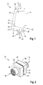
- FIG. 1 a frame 10 is shown, which has two frame parts 12, 14.
- the two frame parts 12, 14 are identical, so that only the frame part 12 is described for the sake of simplicity. Of course, it is conceivable that the frame parts 12, 14 are not identical.
- the frame part 12 is L-shaped and thus has a long leg 16 and a short leg 18, which are arranged at right angles to each other.
- a lever system 20 and a hole 21 are provided, which extends through the frame part 12.
- the lever system 20 has an actuating lever 22 and a clamping lever 24.
- the actuating lever 22 is pivotally mounted on the short leg 18 of the frame part 14.
- the clamping lever 24 is pivotally mounted at one end by means of a hinge axis.
- the hinge axis divides the operating lever 22 into two parts.
- the actuating lever 22 has an eyelet 25, which is arranged for example on the part of the actuating lever 22 farther from the frame part 12.
- the eyelet 25 is disposed on the operating lever 22 such that the eyelet 25 is aligned with the hole 21 when the frame 10 is fully closed.
- the tensioning lever 24 is elongated and made of a flat material so that it defines a plane.
- a clamping element 26 for example in the form of a pin is formed.
- a clamping surface 28 is provided, into which the clamping element 26 of the frame part 14 can engage.
- the clamping surface 28 is formed as a hook into which the clamping element formed as a pin 26 can engage.
- clamping surface 28 is provided on the clamping lever 24 and the clamping element 26 corresponding to the long leg 16 of the frame part 14th
- a contact surface 30 is formed on the inner sides of the legs 16, 18, that is the sides of the legs 16, 18, which face the respective other leg 18, 16.
- the contact surfaces 30 define a receptacle 32 in the frame 10, in the fastening elements 34 (FIG. FIG. 2 ) can be arranged and fixed.
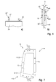
- FIG. 2 a fastener 34 is shown in perspective.
- the FIGS. 3a and 3b show a side or front view of the fastener 34th
- the fastening element 34 has a cuboid base body 36, which has two base surfaces 38 and four side surfaces 40. On the side surfaces 40 projections 42 and recesses 44 are provided to connect a plurality of fasteners 34 together.
- the base body 36 may be hollow or solid. Accordingly, the recess 44 is an opening or a recess.
- a projection 42 is arranged. As in FIG. 3a clearly visible, the projection 42 has a web 46, to which a portion 48 connects. The section 48 is in turn wider than the web 46, so that an undercut 50 is formed.
- the section 48 may, for example, be made round.
- the projection 42 extends parallel to the base surfaces 38. In the embodiment shown, it extends over half the width of the fastener 34th
- one of the recesses 44 is provided on at least one side surface 40 of the fastening element 34.
- the recess 44 may also be made elongated.
- the size and shape of the recess 44 corresponds substantially to the size and the shape of the projection 42, however, the recess 44 is slightly narrower than the width of the portion 48 executed.
- edges of the recess 44 are formed so that they can engage in the undercut 50 of the projection 42 and extend parallel to the web 46 when the projection 42 is received in the recess 44.
- the projection 42 can be inserted into the recess 44, the edge of the recess 44 and / or the portion 48 is formed elastically, in particular made of an elastic material.
- two fasteners 34 can be interconnected by the projection 42 of one of the fasteners 34 is inserted into the recess 44 of another fastener 34 and the edge of the recess 44 engages the undercut 50.
- each side surface 40 each have a projection 42 and a recess 44 is provided, which alternate, one would unwind the side surfaces 40.
- the passage of the cables or lines through the base body 36 takes place through the base surfaces 38 therethrough.
- the base surfaces 38 are preferably square and executed differently depending on the function of the fastener.
- the fastening element 34 is designed as an adapter.
- a plug 54 for example an M12 or M8 plug, is arranged on one of the base surfaces 38 and on the other base surface the coupling 54 complementary to the plug 54.
- the plug 54 is connected to the coupling 56 by electrical lines (not shown) through the base body 36.
- the plug 54 and the coupling 56 are received in the base surfaces 38 via a driving profile 57, for example a hexagon.
- a driving profile 57 for example a hexagon.
- the plug 54 and the coupling 56 can be rotated in defined steps relative to the base surfaces.
- other driving profiles are also conceivable, such as a four- or octagon, whereby other step angles are made possible.
- the plug 54 and the coupling 56 are of different types, so that a change of the cable or termination type is possible by means of the fastener.
- the plug 54 or the coupling 56 is of the type M12 and the respective other of the type M8, so that an M12-M8 adapter is realized.
- the fastening element 34 can also be designed as a plug or coupling (see. FIG. 4 ), in which on a base 38, a plug or a coupling is provided, which are connected by a cable 58, which protrudes from the other base 38, by conductors in the base body 36.
- the fastening element 34 may be designed as a simple cable grommet by an opening 59 is provided by the base body 36 from the one base 38 to the other base 38 (see. FIG. 4 ).
- FIG. 4a Several different fasteners 34 are shown, which can be interconnected.
- FIG. 4a Also shown a fastener 34 'in a second embodiment.
- the fastening element 34 ' has a larger base area 38', which corresponds approximately to four times the base area 38 of the fastening elements 34.
- projections 42 and recesses 44 are also provided, which correspond to those of the fastener 34 of the first embodiment.
- the size of the projections 42 and the recesses 44 and the distance between the projections 42 and the recesses 44 regardless of the size of the base 38, 38 ', so that fasteners 34, 34' with different base surfaces 38th , 38 'are fastened together.
- FIG. 4b are the fasteners 34, 34 'of FIG. 4a now attached to each other and form a cable gland 60 for eight cables or lines. Strictly speaking, it is not a pure cable feedthrough, since the adapter or plug cables are connected only to the cable gland 60. For the sake of simplicity, however, the term “cable feedthrough" will nevertheless be used.
- a cable feedthrough system 62 comprising a frame 10 and a grommet 60.
- the cable duct 60 is arranged in the receptacle 32 of the frame 10.
- the contact surfaces 30 of the frame parts 12, 14 are likewise formed with recesses 44, which can receive the projections 42 of the fastening elements 34, 34'.
- contact surfaces 30 are also provided with projections 42 in order to further improve the fit of the fastening elements 34, 34 'in the frame 10.
- the grommet 60 in the receptacle 32 between the two frame parts 12, 14 is arranged.
- the clamping element 26 of the clamping lever 24 is closer to the plane formed by the contact surface 30 of the short leg 18, as on a plane parallel thereto, in which the connection point between the frame part 12, 14 and the actuating lever 22 is located.
- the fastening elements 34, 34 ' are pressed against each other in such a way that they are pressed both against the adjacent fastening elements 34, 34' in the direction of the long legs 16 of the frame parts 12, 14 and against the adjacent fastening elements 34 in the direction of the short leg 18 of the frame parts 12, 14 are sealed.
- the fastening elements 34 and the cable gland 60 as a whole relative to the frame 10 in the plane of the frame slidably, as long as the frame is not completely closed, but is in a semi-closed position.
- lever systems 20 are designed such that they have a dead center, which must be overcome in order to connect the frame parts 12, 14 completely together.
- This dead center is in the embodiment shown between the positions of FIGS. 5c and 5d .
- FIG. 6a and 6b a further embodiment of a fastener 34 is shown.
- the projections 42 'and recesses 44' are different from those of the previously illustrated embodiments.
- the recess 44 ' has at least two sections 68, 70 with different widths B small , B large .
- the recess 44 ' is in the portion 68 with large marester width B greater than the width b of the hook 67, so that the hook 67 in the recess 44' can be inserted.
- the recess 44 ' has a width B small , which is narrower than the width b of the hook 67th
- the fastening elements 34 are slightly offset relative to each other, so that the hooks 67 are inserted through the sections 68 of the recesses 44 '.
- the hooks 67 are guided into the sections 70 with the smallest width, so that the fasteners 34 can not be separated from each other.
- FIG. 7 a second embodiment of the frame 10 is shown.
- the frame parts 112, 114 are made in several pieces. For simplicity, only frame part 112 will be described because the frame part 114 is identical to it.
- the frame part 112 has two end pieces 112.1, 112.2, which can be interconnected.
- the two end pieces 112.1, 112.2 correspond to the frame part 12 of the first embodiment, when they are directly connected to each other.
- the frame parts 112.1, 112.2 are connected to each other by an extension piece 72, so that in the direction of the long leg 18 longer frame 10 can be generated.
- the frame can be easily enlarged. It is also possible to adapt the frame 10 by adding a plurality of extension pieces 72 according to the required size.
Landscapes
- Engineering & Computer Science (AREA)
- Architecture (AREA)
- Civil Engineering (AREA)
- Structural Engineering (AREA)
- Installation Of Indoor Wiring (AREA)
Applications Claiming Priority (1)
| Application Number | Priority Date | Filing Date | Title |
|---|---|---|---|
| DE102014102790.6A DE102014102790A1 (de) | 2014-03-03 | 2014-03-03 | Rahmen für Kabeldurchführungen, Befestigungselemente sowie Kabeldurchführungssystem |
Publications (2)
| Publication Number | Publication Date |
|---|---|
| EP2916409A2 true EP2916409A2 (fr) | 2015-09-09 |
| EP2916409A3 EP2916409A3 (fr) | 2015-12-23 |
Family
ID=52596788
Family Applications (1)
| Application Number | Title | Priority Date | Filing Date |
|---|---|---|---|
| EP15156718.7A Withdrawn EP2916409A3 (fr) | 2014-03-03 | 2015-02-26 | Cadre pour passe-câble, éléments de fixation et système de passe-câble |
Country Status (2)
| Country | Link |
|---|---|
| EP (1) | EP2916409A3 (fr) |
| DE (1) | DE102014102790A1 (fr) |
Cited By (5)
| Publication number | Priority date | Publication date | Assignee | Title |
|---|---|---|---|---|
| WO2018189182A1 (fr) * | 2017-04-10 | 2018-10-18 | Igus Gmbh | Décharge de traction pour une installation rapide d'une chaîne de transport d'énergie |
| EP3404789A1 (fr) * | 2017-05-16 | 2018-11-21 | Aetec OOO | Passage de conduite et module de passage de conduite d'un tel passage de conduite |
| WO2020089031A1 (fr) * | 2018-10-29 | 2020-05-07 | Icotek Project Gmbh & Co. Kg | Traversée de câble |
| WO2020207796A1 (fr) * | 2019-04-10 | 2020-10-15 | Icotek Project Gmbh & Co. Kg | Dispositif permettant d'insérer des lignes à travers un orifice |
| CN114080729A (zh) * | 2019-07-09 | 2022-02-22 | 库卡德国有限公司 | 用于控制柜的线缆贯通件 |
Citations (1)
| Publication number | Priority date | Publication date | Assignee | Title |
|---|---|---|---|---|
| DE9305975U1 (de) * | 1993-04-20 | 1993-08-05 | Reiku GmbH, 51674 Wiehl | Kabeldurchführungsabdeckung für eine Wandöffnung |
Family Cites Families (10)
| Publication number | Priority date | Publication date | Assignee | Title |
|---|---|---|---|---|
| DE7921514U1 (de) * | 1979-07-27 | 1979-10-25 | Upat Max Langensiepen Kg | Rahmen zum Zusammenhalten von gestapelten Kisten o dgl |
| DE8313278U1 (de) * | 1983-05-05 | 1983-11-03 | Steindorff, Dieter, 3360 Osterode | Rahmenkonstruktion für die Befestigung von Einrichtungsgegenständen eines Wohnmobils |
| DE3727160C1 (de) * | 1987-08-14 | 1988-09-08 | Plastoform Gmbh & Co Kg | Durchfuehrung fuer Leitungen durch eine Wandoeffnung |
| GB2337870A (en) * | 1998-04-29 | 1999-12-01 | Nokia Telecommunications Oy | Modular cable entry system |
| DE19959151C1 (de) * | 1999-12-08 | 2001-08-09 | Klein Guenther Industriebedarf | Vorrichtung zur abgedichteten Durchführung von Kabeln, Leitungen bzw. Rohren in Decken- oder Wanddurchbrüchen von Hochbauten |
| DE102005017689A1 (de) * | 2005-04-08 | 2006-10-12 | Lapp Engineering & Co. | Kabeldurchführung und Kabeldurchführungssystem |
| DE102010037465A1 (de) * | 2010-09-10 | 2012-03-15 | Phoenix Contact Gmbh & Co. Kg | Rahmen für Kabeldurchführungssysteme und Rahmenteile hierfür |
| DE102010037463A1 (de) * | 2010-09-10 | 2012-03-15 | Phoenix Contact Gmbh & Co. Kg | Rahmen eines Kabeleinführungssystems und Kabeltülle hierfür |
| DE202010008917U1 (de) * | 2010-10-28 | 2012-01-30 | SCHÜCO International KG | Rahmenkonstruktion und Einziehwerkzeug |
| DE102012007460A1 (de) * | 2012-04-13 | 2013-10-17 | Pflitsch Gmbh & Co. Kg | Vorrichtung zur Verlegung von Langformteilen durch Gerätewandungen |
-
2014
- 2014-03-03 DE DE102014102790.6A patent/DE102014102790A1/de not_active Ceased
-
2015
- 2015-02-26 EP EP15156718.7A patent/EP2916409A3/fr not_active Withdrawn
Patent Citations (1)
| Publication number | Priority date | Publication date | Assignee | Title |
|---|---|---|---|---|
| DE9305975U1 (de) * | 1993-04-20 | 1993-08-05 | Reiku GmbH, 51674 Wiehl | Kabeldurchführungsabdeckung für eine Wandöffnung |
Cited By (12)
| Publication number | Priority date | Publication date | Assignee | Title |
|---|---|---|---|---|
| WO2018189182A1 (fr) * | 2017-04-10 | 2018-10-18 | Igus Gmbh | Décharge de traction pour une installation rapide d'une chaîne de transport d'énergie |
| CN110800179A (zh) * | 2017-04-10 | 2020-02-14 | 易格斯有限公司 | 用于能量引导链的快速装配的拉力卸载件 |
| US11600981B2 (en) | 2017-04-10 | 2023-03-07 | Igus Gmbh | Strain relief for quick assembly for a cable carrier |
| EP3404789A1 (fr) * | 2017-05-16 | 2018-11-21 | Aetec OOO | Passage de conduite et module de passage de conduite d'un tel passage de conduite |
| WO2020089031A1 (fr) * | 2018-10-29 | 2020-05-07 | Icotek Project Gmbh & Co. Kg | Traversée de câble |
| US11942772B2 (en) | 2018-10-29 | 2024-03-26 | Icotek Project Gmbh & Co. Kg | Cable bushing |
| WO2020207796A1 (fr) * | 2019-04-10 | 2020-10-15 | Icotek Project Gmbh & Co. Kg | Dispositif permettant d'insérer des lignes à travers un orifice |
| CN113950783A (zh) * | 2019-04-10 | 2022-01-18 | 伊科泰克项目有限公司 | 用于通过开口引入管线的装置 |
| JP2022526657A (ja) * | 2019-04-10 | 2022-05-25 | アイコテック・プロジェクト・ゲーエムベーハー・ウント・コー・カーゲー | 開口部を通じて導線を導入するための装置 |
| US20220216649A1 (en) * | 2019-04-10 | 2022-07-07 | Icotek Project Gmbh & Co. Kg | Device for introducing cables through an opening |
| US12040574B2 (en) | 2019-04-10 | 2024-07-16 | Icotek Project Gmbh & Co. Kg | Device for introducing cables through an opening |
| CN114080729A (zh) * | 2019-07-09 | 2022-02-22 | 库卡德国有限公司 | 用于控制柜的线缆贯通件 |
Also Published As
| Publication number | Publication date |
|---|---|
| DE102014102790A1 (de) | 2015-09-03 |
| EP2916409A3 (fr) | 2015-12-23 |
Similar Documents
| Publication | Publication Date | Title |
|---|---|---|
| DE3903839C2 (fr) | ||
| DE102015114702B4 (de) | Halterahmen | |
| DE102011051291A1 (de) | Steckverbinder mit Kammerblock und Kontaktsicherung | |
| DE102015101433B3 (de) | Halterahmen für Steckverbindermodule | |
| WO2015185511A2 (fr) | Appareil électrique | |
| DE102010037465A1 (de) | Rahmen für Kabeldurchführungssysteme und Rahmenteile hierfür | |
| DE102015222561B4 (de) | Halterahmen zur Halterung von Steckverbindermodulen | |
| EP2339701A2 (fr) | Connecteur à fiche de plaquettes doté d'un dispositif de verrouillage | |
| EP2771947A1 (fr) | Connecteur électrique enfichable en deux parties | |
| EP3679631B1 (fr) | Connecteur enfichable comprenant des crochets de verrouillage servant à fixer son support de contact dans son boîtier extérieur | |
| EP2916409A2 (fr) | Cadre pour passe-câble, éléments de fixation et système de passe-câble | |
| DE202013012817U1 (de) | Steckverbinder umfassend eine Schutzleiterbrücke | |
| EP1655813A1 (fr) | Fixation pour connexion électrique | |
| WO2021170175A1 (fr) | Dispositif d'entrée de câble pour armoire de commande, son agencement et son procédé de fonctionnement | |
| EP3756249A1 (fr) | Connecteur comprenant un élément de polarisation ainsi qu'un système et un procédé pour le montage, le branchement et le débranchement de ce connecteur | |
| DE102016217456B3 (de) | Anordnung für einen elektrischen Steckverbinder sowie Steckverbinder mit einem Kontaktgehäuse, Umgehäuse und Sicherungselement | |
| EP2067212B1 (fr) | Connecteur à fiches électrique avec guidage | |
| EP0901190A2 (fr) | Système de traversée câble-fiche | |
| DE9004383U1 (de) | Steckverbinder, insbesondere Zwittersteckverbinder | |
| DE102016104082B3 (de) | Elektrische Steckvorrichtung mit einem Rastmechanismus | |
| DE10393723B4 (de) | Steckverbindung und Montageverfahren zum Herstellen mindestens einer Verbindung durch eine Öffnung in einer Trennwand | |
| DE102021204905A1 (de) | Verwendung einer Einhäusung zum Verhindern eines Heraustretens eines Rohrs oder eines Kabels aus einem ersten Kabelverbinder, Satz, Zusammenbau und ein Verfahren zum Zusammenbauen desselben | |
| DE102017115013B3 (de) | Kontaktträgeranordnung und Verfahren zur Montage der Kontaktträgeranordnung | |
| DE202014100373U1 (de) | Installationsdose | |
| EP2639912B1 (fr) | Boîtier encastrable pour canaux d'intégration d'appareil et canal d'intégration d'appareils doté de celui-ci |
Legal Events
| Date | Code | Title | Description |
|---|---|---|---|
| PUAI | Public reference made under article 153(3) epc to a published international application that has entered the european phase |
Free format text: ORIGINAL CODE: 0009012 |
|
| AK | Designated contracting states |
Kind code of ref document: A2 Designated state(s): AL AT BE BG CH CY CZ DE DK EE ES FI FR GB GR HR HU IE IS IT LI LT LU LV MC MK MT NL NO PL PT RO RS SE SI SK SM TR |
|
| AX | Request for extension of the european patent |
Extension state: BA ME |
|
| PUAL | Search report despatched |
Free format text: ORIGINAL CODE: 0009013 |
|
| AK | Designated contracting states |
Kind code of ref document: A3 Designated state(s): AL AT BE BG CH CY CZ DE DK EE ES FI FR GB GR HR HU IE IS IT LI LT LU LV MC MK MT NL NO PL PT RO RS SE SI SK SM TR |
|
| AX | Request for extension of the european patent |
Extension state: BA ME |
|
| RIC1 | Information provided on ipc code assigned before grant |
Ipc: H02G 3/22 20060101AFI20151119BHEP |
|
| 17P | Request for examination filed |
Effective date: 20160603 |
|
| RBV | Designated contracting states (corrected) |
Designated state(s): AL AT BE BG CH CY CZ DE DK EE ES FI FR GB GR HR HU IE IS IT LI LT LU LV MC MK MT NL NO PL PT RO RS SE SI SK SM TR |
|
| 17Q | First examination report despatched |
Effective date: 20180928 |
|
| GRAP | Despatch of communication of intention to grant a patent |
Free format text: ORIGINAL CODE: EPIDOSNIGR1 |
|
| INTG | Intention to grant announced |
Effective date: 20200316 |
|
| STAA | Information on the status of an ep patent application or granted ep patent |
Free format text: STATUS: THE APPLICATION IS DEEMED TO BE WITHDRAWN |
|
| 18D | Application deemed to be withdrawn |
Effective date: 20200728 |