EP2916448A1 - Dispositif de conversion de puissance et procédé pour diagnostiquer une défaillance du dispositif - Google Patents
Dispositif de conversion de puissance et procédé pour diagnostiquer une défaillance du dispositif Download PDFInfo
- Publication number
- EP2916448A1 EP2916448A1 EP12887726.3A EP12887726A EP2916448A1 EP 2916448 A1 EP2916448 A1 EP 2916448A1 EP 12887726 A EP12887726 A EP 12887726A EP 2916448 A1 EP2916448 A1 EP 2916448A1
- Authority
- EP
- European Patent Office
- Prior art keywords
- power supply
- electric machine
- fault
- armature windings
- polyphase dynamo
- Prior art date
- Legal status (The legal status is an assumption and is not a legal conclusion. Google has not performed a legal analysis and makes no representation as to the accuracy of the status listed.)
- Granted
Links
Images





Classifications
-
- H—ELECTRICITY
- H02—GENERATION; CONVERSION OR DISTRIBUTION OF ELECTRIC POWER
- H02P—CONTROL OR REGULATION OF ELECTRIC MOTORS, ELECTRIC GENERATORS OR DYNAMO-ELECTRIC CONVERTERS; CONTROLLING TRANSFORMERS, REACTORS OR CHOKE COILS
- H02P6/00—Arrangements for controlling synchronous motors or other dynamo-electric motors using electronic commutation dependent on the rotor position; Electronic commutators therefor
- H02P6/12—Monitoring commutation; Providing indication of commutation failure
-
- H—ELECTRICITY
- H02—GENERATION; CONVERSION OR DISTRIBUTION OF ELECTRIC POWER
- H02M—APPARATUS FOR CONVERSION BETWEEN AC AND AC, BETWEEN AC AND DC, OR BETWEEN DC AND DC, AND FOR USE WITH MAINS OR SIMILAR POWER SUPPLY SYSTEMS; CONVERSION OF DC OR AC INPUT POWER INTO SURGE OUTPUT POWER; CONTROL OR REGULATION THEREOF
- H02M1/00—Details of apparatus for conversion
- H02M1/32—Means for protecting converters other than automatic disconnection
-
- H—ELECTRICITY
- H02—GENERATION; CONVERSION OR DISTRIBUTION OF ELECTRIC POWER
- H02M—APPARATUS FOR CONVERSION BETWEEN AC AND AC, BETWEEN AC AND DC, OR BETWEEN DC AND DC, AND FOR USE WITH MAINS OR SIMILAR POWER SUPPLY SYSTEMS; CONVERSION OF DC OR AC INPUT POWER INTO SURGE OUTPUT POWER; CONTROL OR REGULATION THEREOF
- H02M7/00—Conversion of AC power input into DC power output; Conversion of DC power input into AC power output
- H02M7/42—Conversion of DC power input into AC power output without possibility of reversal
- H02M7/44—Conversion of DC power input into AC power output without possibility of reversal by static converters
- H02M7/48—Conversion of DC power input into AC power output without possibility of reversal by static converters using discharge tubes with control electrode or semiconductor devices with control electrode
- H02M7/53—Conversion of DC power input into AC power output without possibility of reversal by static converters using discharge tubes with control electrode or semiconductor devices with control electrode using devices of a triode or transistor type requiring continuous application of a control signal
- H02M7/537—Conversion of DC power input into AC power output without possibility of reversal by static converters using discharge tubes with control electrode or semiconductor devices with control electrode using devices of a triode or transistor type requiring continuous application of a control signal using semiconductor devices only, e.g. single switched pulse inverters
- H02M7/5387—Conversion of DC power input into AC power output without possibility of reversal by static converters using discharge tubes with control electrode or semiconductor devices with control electrode using devices of a triode or transistor type requiring continuous application of a control signal using semiconductor devices only, e.g. single switched pulse inverters in a bridge configuration
-
- G—PHYSICS
- G01—MEASURING; TESTING
- G01R—MEASURING ELECTRIC VARIABLES; MEASURING MAGNETIC VARIABLES
- G01R31/00—Arrangements for testing electric properties; Arrangements for locating electric faults; Arrangements for electrical testing characterised by what is being tested not provided for elsewhere
- G01R31/40—Testing power supplies
- G01R31/42—AC power supplies
Definitions
- the present invention relates to a power conversion device and a fault diagnosis method therefor, in particular, a power conversion device for supplying electric power to a polyphase dynamo-electric machine or rectifying an induction voltage from the polyphase dynamo-electric machine, and a fault diagnosis method for the power conversion device.
- Patent Literature 1 there is proposed a method of detecting a short circuit fault in a diode of a full-wave rectifying circuit with high precision. More specifically, a voltage source or a current source is connected to an arbitrary AC terminal to determine an abnormality based on a voltage value or a current value of the AC terminal.
- Patent Literature 1 normality is determined based on the fact that no current flows from a fault detection terminal (P terminal) to an armature winding, and hence there is a problem in that, in a case where a path from the fault detection terminal (P terminal) to the armature winding is open-circuited, not only it is impossible to detect the open circuit, but it is also impossible to detect a short circuit fault in the full-wave rectifying circuit, or to detect a power fault and an earth fault in the armature winding.
- the present invention has been made to solve the above-mentioned problem, and it is an object of the present invention to provide a power conversion device capable of detecting a power fault, an earth fault, and an open fault of a polyphase dynamo-electric machine without causing a large current to flow, and a fault diagnosis method for the power conversion device.
- a power conversion device in which a plurality of phase bridge circuits each including power semiconductor switching elements, which are connected in series with each other to construct an upper arm and a lower arm, are connected in parallel to one another, both terminals of the plurality of phase bridge circuits are connected to a DC power supply, which is chargeable and dischargeable, and nodes between the power semiconductor switching elements of the upper arm and the lower arm of the plurality of phase bridge circuits are connected to AC terminals of armature windings of a polyphase dynamo-electric machine, for performing AC-DC power conversion or DC-AC power conversion, the power conversion device including: an internal power supply circuit; a driving circuit for turning on or off the power semiconductor switching elements; a discharge type constant current circuit for connecting an output terminal of the internal power supply circuit and one of the AC terminals of the armature windings of the polyphase dynamo-electric machine, to thereby cause a constant current to flow from the output terminal of the internal power supply circuit to the one of the
- the power conversion device in which the plurality of phase bridge circuits each including the power semiconductor switching elements, which are connected in series with each other to construct the upper arm and the lower arm, are connected in parallel to one another, both terminals of the plurality of phase bridge circuits are connected to the DC power supply, which is chargeable and dischargeable, and the nodes between the power semiconductor switching elements of the upper arm and the lower arm of the plurality of phase bridge circuits are connected to the AC terminals of the armature windings of the polyphase dynamo-electric machine, for performing AC-DC power conversion or DC-AC power conversion, includes: the internal power supply circuit; the driving circuit for turning on or off the power semiconductor switching elements; the discharge type constant current circuit for connecting the output terminal of the internal power supply circuit and one of the AC terminals of the armature windings of the polyphase dynamo-electric machine, to thereby cause the constant current to flow from the output terminal of the internal power supply circuit to the one of the AC terminals of the armature windings
- FIG. 1 illustrates a configuration of a power conversion device according to a first embodiment of the present invention.
- a power conversion device 1 is configured so that a predetermined number of (three in FIG. 1 ) phase bridge circuits each including two power semiconductor switching elements 2, which are connected in series with each other to construct upper and lower arms, are connected in parallel to one another. Both terminals (a pair of terminals) of the phase bridge circuits are connected to a DC power supply 3, which is chargeable and dischargeable, and nodes between the power semiconductor switching elements 2 constituting the phase bridge circuits are respectively connected to AC terminals of armature windings of respective phases of a polyphase dynamo-electric machine 4.
- the power conversion device 1 performs AC-DC power conversion or DC-AC power conversion between an internal power supply circuit 6 and the DC power supply 3.
- a three-phase dynamo-electric machine is exemplified as the polyphase dynamo-electric machine 4. Therefore, in the following description, the polyphase dynamo-electric machine 4 is described as the three-phase dynamo-electric machine. However, the present invention is not limited to such case, and the number of phases of the polyphase dynamo-electric machine 4 may be two, six, or the like, or the polyphase dynamo-electric machine 4 may be a star-connected dynamo-electric machine.
- the power conversion device 1 includes six power semiconductor switching elements 2, a driving circuit 5, the internal power supply circuit 6, a discharge type constant current circuit 7, a backflow prevention diode 8, pull-down resistors 9, phase voltage detection units 10, and a fault determination unit 11.
- the driving circuit 5 turns on or off each of the six power semiconductor switching elements 2.
- the internal power supply circuit 6 outputs a predetermined voltage from an output terminal 6a.
- the discharge type constant current circuit 7 is connected to the output terminal 6a of the internal power supply circuit 6 to cause a constant current to flow from the output terminal 6a of the internal power supply circuit 6 to an arbitrary one of the AC terminals of the armature windings of the polyphase dynamo-electric machine 4.
- the backflow prevention diode 8 is connected between the discharge type constant current circuit 7 and the AC terminal of the armature windings of the polyphase dynamo-electric machine 4 to prevent a backflow current from the AC terminal of the armature windings of the polyphase dynamo-electric machine 4 to the internal power supply circuit 6.
- the pull-down resistors 9 respectively connect the other two AC terminals of the armature windings of the polyphase dynamo-electric machine 4, which are not connected to the discharge type constant current circuit 7, to a cathode potential of the DC power supply 3.
- the phase voltage detection units 10 detect phase voltages of the armature windings of the polyphase dynamo-electric machine 4.
- the fault determination unit 11 determines, based on values of the phase voltages of respective phases of the polyphase dynamo-electric machine 4, which are detected by the phase voltage detection units 10, a power fault (or line-to-power fault), an earth fault (or ground fault or line-to-ground fault), and an open fault of armature windings of the polyphase dynamo-electric machine 4.
- power fault means that insulation between an armature winding of the polyphase dynamo-electric machine 4 and the DC power supply 3 is extremely lowered so that a connection is established therebetween by arcing or a conductor.
- a case where a wiring is brought into contact with an anode terminal (power supply line) of the DC power supply 3 is exemplified.
- all the phase voltages of the polyphase dynamo-electric machine 4 become substantially equal to an anode potential of the DC power supply 3.
- substantially as used herein means that, even when detection errors of the phase voltage detection units 10 are subtracted, the phase voltages of the polyphase dynamo-electric machine 4 are equal to the anode potential of the DC power supply 3.
- the term "earth fault” means that insulation between an armature winding of the polyphase dynamo-electric machine 4 and a GND terminal is extremely lowered so that a connection is established therebetween by arcing or a conductor. For example, a case where a wiring is brought into contact with a ground wire is exemplified.
- all the phase voltages of the polyphase dynamo-electric machine 4 become substantially equal to the cathode potential of the DC power supply 3.
- substantially as used herein means that, even when the detection errors of the phase voltage detection units 10 are subtracted, the phase voltages of the polyphase dynamo-electric machine 4 are equal to the cathode potential of the DC power supply 3.
- open fault means that a part of wirings of the armature windings of the polyphase dynamo-electric machine 4 is open-circuited. When the open fault occurs, all the phase voltages of the polyphase dynamo-electric machine become not substantially the same potential.
- substantially as used herein means that, even when the detection errors of the phase voltage detection units 10 are subtracted, all the phase voltages of the polyphase dynamo-electric machine 4 are the same potential as one another.
- the power semiconductor switching elements 2 include, for example, MOSFETs or IGBTs.
- the DC power supply 3 includes, for example, a lead accumulator (battery), a lithium ion battery, or an electric double layer capacitor, which is generally used as a power supply for an automobile.
- the driving circuit 5 includes, for example, a push-pull type predriver using a driving power supply using a charge pump circuit or a bootstrap circuit.
- the internal power supply circuit 6 includes, for example, a DC-DC converter, a series regulator, or a constant voltage diode.
- the discharge type constant current circuit 7 includes, for example, a constant current diode, or a constant current circuit using transistors, such as a current mirror circuit.
- the phase voltage detection units 10 include, for example, transistors, or differential amplifier circuits using operational amplifiers.
- the phase voltages of the polyphase dynamo-electric machine 4 at the time need to be differentiated from the cathode potential of the DC power supply 3, and hence there needs to be a potential difference between the phase voltages of the polyphase dynamo-electric machine 4 and the cathode potential of the DC power supply 3.
- the constant current value of the discharge type constant current circuit 7 is 10 mA by the Ohm's Law.
- the discharge type constant current circuit 7 is used to cause the constant current to flow, and hence even when the leakage from the armature windings of the polyphase dynamo-electric machine 4 to the cathode potential of the DC power supply 3 due to salt water or mud water occurs, it is possible to avoid falsely determining the earth fault.
- the resistance value of the pull-down resistors 9 is set in consideration of the fact that the phase voltages of the polyphase dynamo-electric machine 4 increase up to an anode voltage of the DC power supply 3 due to a power fault of an armature winding of the polyphase dynamo-electric machine 4 or a short circuit fault of a power semiconductor switching element 2 constituting an upper arm.
- a leakage current flows from the driving circuit 5 to the AC terminals of the armature windings of the polyphase dynamo-electric machine 4, and hence there is a need to avoid a phenomenon in which the leakage current increases potentials of both terminals of the pull-down resistors 9 and stops a flow of a minute current which flows so as to detect a fault in the polyphase dynamo-electric machine 4.
- the fault determination unit 11 includes, for example, a logic circuit such as a microcomputer or an ASIC, or a comparing unit such as a comparator.
- the fault determination unit 11 starts a fault determination in a state in which all the power semiconductor switching elements 2 are in the off state and no induction voltage is generated in the armature windings of the polyphase dynamo-electric machine 4, and when a fault determination start signal is received from a control unit (not shown) of the power conversion device 1 or a host controller (not shown) of the power conversion device 1.
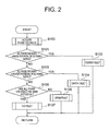
- the fault determination unit 11 uses the internal power supply circuit 6 to cause the minute current to flow through the armature windings of the polyphase dynamo-electric machine 4, and detects the phase voltages to perform the fault determination based on the detected phase voltages. Operation of the fault determination is described below with reference to a flow chart illustrated in FIG. 2 .
- Step S100 all the phase voltages of the armature windings of the polyphase dynamo-electric machine 4 are acquired from the phase voltage detection units 10.
- Step S101 it is determined whether or not all the phase voltages are substantially equal to the anode potential of the DC power supply 3, and when all the phase voltages are substantially equal to the anode potential, the processing transitions to Step S102.
- Step S102 the power fault is determined, and the fault determination processing is ended.
- the term "substantially" as used in Step S101 means that, even when the detection errors of the phase voltage detection units 10 are subtracted, the phase voltages are equal to the anode potential of the DC power supply 3.
- Step S103 it is determined whether or not all the phase voltages are substantially equal to the cathode potential of the DC power supply 3, and when all the phase voltages are substantially equal to the cathode potential, the processing transitions to Step S104.
- Step S104 the earth fault is determined, and the fault determination processing is ended.
- Step S105 when all the phase voltages are not substantially the same potential, the processing transitions to Step S106.
- Step S106 the open fault is determined, and the fault determination processing is ended.
- the processing proceeds to Step S107, and in Step S107, it is determined that none of the power fault, the earth fault, and the open fault has occurred in the polyphase dynamo-electric machine 4, and the fault determination processing is ended.
- a value of the predetermined voltage output by the internal power supply circuit 6 be set to a value smaller than a minimum value of the voltage fluctuation range of the DC power supply 3 in which the power conversion device 1 operates normally.
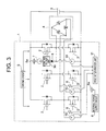
- FIG. 3 illustrates a modified example of FIG. 1
- a constant voltage unit 30 is connected in series with the backflow prevention diode 8.
- the constant voltage unit 30 is provided between the discharge type constant current circuit 7 and the backflow prevention diode 8.
- the other components are the same as in FIG. 1 , and hence a description thereof is omitted here.
- the constant voltage unit 30 increases (or amplifies) the potential difference between the output voltage of the internal power supply circuit 6 and the phase voltages of the armature windings of the polyphase dynamo-electric machine 4.
- the constant voltage unit 30 includes, for example, a constant voltage diode having a cathode side connected to the output terminal 6a of the internal power supply circuit 6.
- the constant voltage unit 30 may include at least one diode, and a voltage drop in the forward direction of the at least one diode may be utilized to connect an anode side of the at least one diode to the output terminal 6a of the internal power supply circuit 6.
- the constant voltage unit 30 is provided to increase the potential difference between the output voltage of the internal power supply circuit 6 and the phase voltages of the armature windings of the polyphase dynamo-electric machine 4, with the result that even when the anode potential of the DC power supply 3 is lower than a value of the output voltage of the internal power supply circuit 6, the power fault can be detected precisely.
- the internal power supply circuit 6 is used to cause the minute current to flow through the armature windings of the polyphase dynamo-electric machine 4, and the respective phase voltages are detected by the phase voltage detection units 10 so that the fault determination is performed based on the detected phase voltages, with the result that the power, earth, and open faults of the polyphase dynamo-electric machine 4 can be detected accurately.
- the discharge type constant current circuit 7 is used to cause the constant current to flow, with the result that even when the leakage from the armature windings of the polyphase dynamo-electric machine 4 to the cathode potential of the DC power supply 3 due to salt water or mud water occurs, it is possible to avoid falsely determining the earth fault.
- the resistance value of the pull-down resistors 9 is selected appropriately, with the result that it is possible to prevent the problem in that the leakage current from the driving circuit 5 stops the minute current for detecting the fault from flowing through the polyphase dynamo-electric machine 4, and even when a power fault occurs in an armature winding of the polyphase dynamo-electric machine 4 or a short circuit fault occurs in a power semiconductor switching element 2 constituting an upper arm of a phase bridge circuit, there is no fear that a pull-down resistor 9 is burned by exceeding the rating so that a secondary fault can be prevented.
- the output voltage of the internal power supply circuit 6 is set to the value smaller than the minimum value of the voltage fluctuation range of the DC power supply 3 in which the power conversion device 1 operates normally, with the result that the fault determination processing can be realized without a false determination.
- the constant voltage unit 30 to decrease the phase voltage value at the time of no fault as in the modified example illustrated in FIG. 3 , even when the anode potential of the DC power supply 3 is lower than the output voltage of the internal power supply circuit 6, the power fault can be detected precisely.
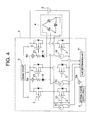
- FIG. 4 illustrates a configuration of a power conversion device according to a second embodiment of the present invention.
- a sink type constant current circuit 20 is connected between an arbitrary one of the AC terminals of the armature windings of the polyphase dynamo-electric machine 4 and the cathode potential of the DC power supply 3, the other two AC terminals of the armature windings of the polyphase dynamo-electric machine 4 are connected to the output terminal 6a of the internal power supply circuit 6 via pull-up resistors 21 and the backflow prevention diodes 8, and the pull-down resistors 9 in FIG. 1 are not provided.
- the other components and operation are the same as in FIG. 1 , and hence a description thereof is omitted here.
- operation of the fault determination unit 11 in this embodiment is the same as the processing of the flow chart of FIG. 2 described above in the first embodiment, and hence a description thereof is omitted here.
- the sink type constant current circuit 20 includes, as with the discharge type constant current circuit 7 illustrated in FIG. 1 , for example, a constant current diode, or a constant current circuit using transistors, such as a current mirror circuit.
- a constant current value of the sink type constant current circuit 20 similar to the discharge type constant current circuit 7 described above, there needs to be such a potential difference that the phase voltages and the anode potential of the DC power supply 3 may be differentiated in the case where the leakage from the armature windings of the polyphase dynamo-electric machine to the anode potential of the DC power supply due to salt water or mud water occurs.
- the constant current value is 10 mA by the Ohm's Law.
- the leakage current flows from the driving circuit 5 to the AC terminals of the armature windings of the polyphase dynamo-electric machine 4, and hence the constant current value of the sink type constant current circuit 20 needs to be set at least larger than the leakage current. Otherwise, the leakage current flows to the DC power supply 3 through body diodes of the power semiconductor switching elements 2 and the phase voltages become equal to or larger than the anode potential of the DC power supply 3, which causes the fault determination unit 11 to falsely determine the power fault.
- the constant current value icd may be set as Expression 3 below, for example, by adding the leakage current to the constant current value calculated from the potential difference VL required at the time of the leakage to the anode potential of the DC power supply 3 and the minimum value RL of the expected leakage resistance.
- the leakage current per phase from the driving circuit 5 is represented by im, and the number of phases is represented by n.
- icd VL / RL + im ⁇ n
- the pull-up resistors 21 have the role of decreasing the phase voltages.
- a resistance value of the pull-up resistors 21 is set too large, a constant current of the sink type constant current circuit 20 causes a voltage between both terminals of the pull-up resistors 21 to become too large, and the phase voltages are decreased to near the cathode potential of the DC power supply 3.
- a rated power of the pull-up resistors 21 needs to be a rated power capable of withstanding even a maximum constant current value of the sink type constant current circuit 20 with one pull-up resistor 21. Therefore, with the rated power of the pull-up resistors 21 being represented by P, a safety factor such as a temperature derating being represented by ⁇ (for example, 0.7 or 0.8), and the constant current value of the sink type constant current circuit 20 being represented by icd, the resistance value Rpu of the pull-up resistors 21 needs to satisfy Expression 5 below.
- the resistance value of the pull-up resistors 21 is set to be, for example, as large as about three to four times the expected minimum value of the leakage resistance, which occurs due to salt water or mud water, even when salt water or mud water causes the leakage in the armature windings of the polyphase dynamo-electric machine 4 to the anode potential or the cathode potential of the DC power supply 3, it is possible for the fault determination unit 11 to avoid falsely determining the power fault and the earth fault.
- the internal power supply circuit 6 may be used to cause the minute current to flow through the armature windings of the polyphase dynamo-electric machine 4, and the fault determination may be performed based on each of the phase voltages, with the result that the power fault, the earth fault, and the open fault of the polyphase dynamo-electric machine 4 can be detected accurately.
- the sink type constant current circuit 20 is used to cause the constant current to flow, with the result that even when the leakage from the armature windings of the polyphase dynamo-electric machine 4 to the anode potential of the DC power supply 3 due to salt water or mud water occurs, it is possible to avoid falsely determining the power fault.
- the resistance value of the pull-up resistors 21 is selected appropriately, with the result that it is possible to avoid falsely determining the power fault and the earth fault even for the leakage from the armature windings of the polyphase dynamo-electric machine 4 to the anode potential or the cathode potential of the DC power supply 3 due to salt water or mud water.
- the resistance value of the pull-up resistors 21 is selected appropriately, with the result that even when the anode potential of the DC power supply 3 is lower than the output voltage of the internal power supply circuit 6, the power fault may be detected accurately.
- FIG. 5 illustrates a configuration of a power conversion device according to a third embodiment of the present invention.
- a difference resides in that a sink type constant current circuit 20 is connected in series with an arbitrary one of the pull-down resistors 9.
- the other components and operation are the same as in the first embodiment, and hence a description thereof is omitted here.
- operation of the fault determination unit 11 in this embodiment is the same as the processing of the flow chart of FIG. 2 described above in the first embodiment, and hence a description thereof is omitted here.
- the constant current value of the discharge type constant current circuit 7 may be set in the same manner as in the first embodiment described above, and it is possible to avoid falsely determining the earth fault even for the leakage from the armature windings of the polyphase dynamo-electric machine 4 to the cathode potential of the DC power supply 3 due to salt water or mud water.
- the constant current value of the sink type constant current circuit 20 may also be set in the same manner as in the second embodiment described above, and it is possible to avoid falsely determining the power fault even for the leakage from the armature windings of the polyphase dynamo-electric machine 4 to the anode potential of the DC power supply 3 due to salt water or mud water.
- the resistance value of the other pull-down resistor 9 which is not connected in series with the sink type constant current circuit 20 may be selected to satisfy Expressions 1 and 2 described above.
- the pull-down resistor 9 which is connected in series with the sink type constant current circuit 20 has the role of adjusting the phase voltage similar to the constant voltage unit 30 illustrated in FIG. 3 . More specifically, in the state in which all the power semiconductor switching elements 2 are in the off state and no induction voltage is generated in the armature windings of the polyphase dynamo-electric machine 4, with the phase voltage being represented by Vu, the constant current value of the discharge type constant current circuit 7 being represented by icu, and the resistance value of the pull-down resistor 9 which is not connected in series with the sink type constant current circuit 20 being represented by Rpdn, a resistance value Rpd1 of the pull-down resistor 9 which is connected in series with the sink type constant current circuit 20 may be determined using Expression 6 below.
- Rpd ⁇ 1 Rpdn ⁇ icu - Vu / Rpdn ⁇ Vu
- the resistance value of the pull-down resistor 9 which is connected in series with the sink type constant current circuit 20 needs to be selected so as not to limit the current that flows to the sink type constant current circuit 20 when the leakage from the armature windings of the polyphase dynamo-electric machine 4 to the anode potential of the DC power supply 3 due to salt water or mud water occurs. More specifically, with the minimum value of the voltage fluctuation range of the DC power supply 3 in which the power conversion device 1 operates normally being represented by Batt(MIN), the constant current value of the sink type constant current circuit 7 being represented by icd, and the minimum value of the expected leakage resistance being represented by RL, the resistance value Rpd1 of the pull-down resistor 9 needs to satisfy Expression 7 below. Rpd ⁇ 1 ⁇ Batt MIN / icd - RL
- the internal power supply circuit 6 is used to cause the minute current to flow through the armature windings of the polyphase dynamo-electric machine 4, and the fault determination is performed based on each of the phase voltages, with the result that the power fault, the earth fault, and the open fault of the polyphase dynamo-electric machine 4 can be detected accurately.
- the sink type constant current circuit 20 is used to cause the constant current to flow, with the result that even for the leakage from the armature windings of the polyphase dynamo-electric machine 4 to the cathode potential of the DC power supply 3 due to salt water or mud water, it is possible to avoid falsely determining the earth fault.
- the discharge type constant current circuit 7 is used to cause the constant current to flow, with the result that even for the leakage from the armature windings of the polyphase dynamo-electric machine 4 to the cathode potential of the DC power supply 3 due to salt water or mud water, it is possible to avoid falsely determining the earth fault.
- the resistance value of the pull-down resistor 9 which is connected in series with the sink type constant current circuit 20 is selected appropriately, with the result that the power fault can be detected precisely even when the anode potential of the DC power supply 3 is lower than the output voltage of the internal power supply circuit 6.
- the one of the AC terminals of the armature windings of the polyphase dynamo-electric machine 4 namely the AC terminal which is connected to neither the discharge type constant current circuit 7 nor the sink type constant current circuit 20, may be connected to the output terminal 6a of the internal power supply circuit 6 via the pull-up resistor 21 and the backflow prevention diode 8 similar to the second embodiment described above, and also in that case, it is possible to obtain similar effects.
- the pull-up resistors 21 in FIG. 4 are mounted for the purpose of detecting the open fault.
- the resistance value is set to be sufficiently larger than that of the pull-down resistor 9, and it is preferred to use the resistance value of several k ⁇ to several tens of k ⁇ , for example.
- the resistance value Rpd1 of the pull-down resistor 9 which is connected in series with the sink type constant current circuit 20 may be determined using Expression 8 below, instead of Expression 5 described above,.
- Rpd ⁇ 1 Vu / icd
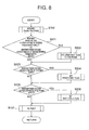
- FIG. 6 illustrates a configuration of a power conversion device according to a fourth embodiment of the present invention.
- a second internal power supply circuit 40 for outputting a voltage that is smaller than the output voltage of the internal power supply circuit 6 is added, and the pull-down resistors 9 connect the AC terminals of the armature windings of the polyphase dynamo-electric machine 4 and an output terminal 40a of the second internal power supply circuit 40.
- the other components and operation are the same as in FIG. 1 .
- the second internal power supply circuit 40 is provided to detect an occurrence of a combined fault such as when a power fault occurs in an armature winding of the polyphase dynamo-electric machine 4 and at the same time an open fault occurs.
- the second internal power supply circuit 40 includes, for example, a DC-DC converter, a series regulator, or a constant voltage diode.
- the output voltage of the second internal power supply circuit 40 is set to be a value that is lower than the output voltage of the internal power supply circuit 6.
- the output voltage of the second internal power supply circuit 40 it is possible to adopt a method of setting the output voltage of the second internal power supply circuit 40 to, for example, a value that is equal to or lower than the potential difference required at the time of occurrence of the leakage from the armature windings of the polyphase dynamo-electric machine 4 to the cathode potential of the DC power supply 3 due to salt water or mud water.
- the output voltage of the second internal power supply circuit 40 is lower than the phase voltage value in the state in which all the power semiconductor switching elements 2 are in the off state and no induction voltage is generated in the armature windings of the polyphase dynamo-electric machine 4 and at the time of no fault, and the method of setting the constant current of the discharge type constant current circuit 7, which is described in the first embodiment, can be used directly without causing a current to flow from the output voltage of the second internal power supply circuit 40 to the AC terminals of the armature windings of the polyphase dynamo-electric machine 4, with the result that similar effects to those of the first embodiment may be obtained.
- the resistance value of the pull-down resistors 9 can be calculated by means of computation in which the output voltage of the second internal power supply circuit 40 is subtracted from the output voltage Vcc of the internal power supply circuit 6 in Expressions 1 and 2 described above or the anode potential of the DC power supply 3, with the result that similar effects to those of the first embodiment may be obtained.
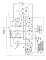
- FIG. 7 illustrates a modified example of the power conversion device according to the fourth embodiment of the present invention.
- the second internal power supply circuit 40, a diode 41, and a resistor 42 are added, and the sink type constant current circuit 20 connects an AC terminal of the armature windings of the polyphase dynamo-electric machine 4 and the output terminal 40a of the second internal power supply circuit 40.
- the other components and operation are the same as in FIG. 4 .
- the second internal power supply circuit 40 outputs the voltage that is smaller than the output voltage of the internal power supply circuit 6.
- the diode 41 and the resistor 42 are connected in parallel to the sink type constant current circuit 20.
- the diode 41 prevents a current from flowing from the AC terminal of the armature windings of the polyphase dynamo-electric machine 4 to the output terminal 40a of the second internal power supply circuit 40.
- the resistor 42 has the role of limiting the current that flows from the output terminal 40a of the second internal power supply circuit 40 to the cathode potential of the DC power supply 3, when an earth fault occurs in an AC terminal of the armature windings of the polyphase dynamo-electric machine 4.
- the output voltage of the second internal power supply circuit 40 may be set to the value that is lower than the output voltage of the internal power supply circuit 6. More specifically, for example, it is possible to adopt the method of setting the output voltage of the second internal power supply circuit 40 to the value that is equal to or lower than the potential difference required at the time of occurrence of the leakage from the armature windings of the polyphase dynamo-electric machine 4 to the cathode potential of the DC power supply 3 due to salt water or mud water.
- the output voltage of the second internal power supply circuit 40 is lower than the phase voltage value in the state in which all the power semiconductor switching elements 2 are in the off state and no induction voltage is generated in the armature windings of the polyphase dynamo-electric machine 4 and at the time of no fault.
- the method of setting the constant current of the sink type constant current circuit 20, which is described in the second embodiment can be used directly without causing the current to flow from the output voltage of the second internal power supply circuit 40 to the AC terminals of the armature windings of the polyphase dynamo-electric machine 4, with the result that similar effects to those of the second embodiment can be obtained.
- the resistance value can be calculated by means of computation in which the output voltage of the second internal power supply circuit 40 is subtracted from the output voltage Vcc of the internal power supply circuit 6 in Expression 4 described above, with the result that similar effects to those of the second embodiment can be obtained.
- the fault determination unit 11 includes, for example, a logic circuit such as a microcomputer or an ASIC, or a comparing unit such as a comparator. In this embodiment also, the fault determination unit 11 starts the fault determination in the state in which all the power semiconductor switching elements 2 are in the off state and no induction voltage is generated in the armature windings of the polyphase dynamo-electric machine 4, and when the fault determination start signal is received from the control unit (not shown) of the power conversion device 1 or the host controller (not shown) of the power conversion device 1.
- the fault determination unit 11 uses the internal power supply circuit 6 and the second internal power supply circuit 40 to cause the minute current to flow through the armature windings of the polyphase dynamo-electric machine 4, and detects the phase voltages to perform the fault determination based on the detected phase voltages.
- Step S100 of FIG. 8 is similar to Step S100 of FIG. 2 , and the phase voltages of the armature windings of the polyphase dynamo-electric machine 4 are acquired from the phase voltage detection units 10.
- Step S201 it is determined whether each of the phase voltages is substantially equal to the output voltage of the internal power supply circuit 6 or substantially equal to the output voltage of the second internal power supply circuit 40.
- the processing transitions to Step S202.
- Step S202 an open fault flag is set to the phase, and the processing proceeds to Step S203.
- Step S203 it is determined whether or not each of the phase voltages is substantially equal to the anode potential of the DC power supply 3. As a result of the determination, in a case where at least one of the phase voltages is substantially equal to the anode potential of the DC power supply 3, the processing proceeds to Step S204. In Step S204, a power fault flag is set to the phase, and the processing proceeds to Step S205.
- Step S205 it is determined whether or not each of the phase voltages is substantially equal to the cathode potential of the DC power supply 3. As a result of the determination, in a case where at least one of the phase voltages is substantially equal to the cathode voltage of the DC power supply 3, the processing proceeds to Step S206. In Step S206, an earth fault flag is set to the phase, and the fault determination processing is ended. On the other hand, in a case where all the phase voltages are substantially different from the cathode potential of the DC power supply 3 in Step S205, the processing proceeds to Step S107.
- Step S107 similar to Step S107 of FIG. 2 , it is determined that no fault has occurred, and the fault determination processing is ended. Moreover, by checking the flag set in Steps S202, S204, and/or S206, it can be confirmed what fault has occurred in what phase, with the result that the power fault, the earth fault, and the open fault of the polyphase dynamo-electric machine 4 can be detected accurately, and a combined fault in which two or more of the above-mentioned faults have occurred simultaneously can also be detected.
- the internal power supply circuit 6 and the second internal power supply circuit 40 are used to cause the minute current to flow through the armature windings of the polyphase dynamo-electric machine 4, and the fault determination is performed based on the respective phase voltages, with the result that the power fault, the earth fault, and the open fault of the polyphase dynamo-electric machine 4 can be detected accurately.
- the second internal power supply circuit 40 is newly provided, and one or more of the AC terminals of the armature windings of the polyphase dynamo-electric machine 4, namely the AC terminal(s) which is/are otherwise connected to the cathode potential of the DC power supply 3, is/are connected to the second internal power supply circuit 40, and the output voltage of the second internal power supply circuit 40 is set appropriately, with the result that the combined fault in which, for example, the open fault and the power fault of the armature windings of the polyphase dynamo-electric machine 4 occur simultaneously can also be detected.
- the second internal power supply circuit 40 may be newly provided, and one or more of the AC terminals of the armature windings of the polyphase dynamo-electric machine 4, namely the AC terminals which are otherwise connected to the cathode potential of the DC power supply 3, may be connected to the second internal power supply circuit 40, and the output voltage of the second internal power supply circuit 40 may be set appropriately, with the result that the combined fault in which, for example, the open fault and the power fault of the armature windings of the polyphase dynamo-electric machine 4 occur simultaneously may also be detected.
- the inability to drive the power semiconductor switching element 2 includes a fault in which the power semiconductor switching element 2 cannot be turned on, and a fault in which the power semiconductor switching element 2 cannot be turned off.
- the fifth embodiment may be applied to every fault determination unit 11 in the first to fourth embodiments, and similar effects may be obtained in any case of applying the fifth embodiment to any of the embodiments.
- the operation other than operation illustrated in FIGS. 9A and 9B to be described below is the same as in the first to fourth embodiments, and hence a description thereof is omitted here.
- a configuration of the power conversion device in the fifth embodiment is the same as the configuration described in each of the first to fourth embodiments. Therefore, a description thereof is omitted here.
- Step S300 the fault determination unit 11 turns on a power semiconductor switching element 2 constituting a lower arm of an arbitrary phase via the driving circuit 5. Then, a predetermined period of time is waited until the phase voltage stabilizes in Step S301, and the processing proceeds to Step S302. A method of setting the predetermined period of time is described in detail later.
- Step S302 the phase voltage of the phase in which the power semiconductor switching element 2 is turned on is acquired via the phase voltage detection unit 10, and the processing proceeds to Step S303.
- Step S303 it is determined whether or not the acquired phase voltage is substantially higher than the cathode potential of the DC power supply 3. As a result of the determination, when the acquired phase voltage is substantially higher, the processing proceeds to Step S304. In Step S304, it is determined that the fault in which the power semiconductor switching element 2 cannot be turned on has occurred and that the power semiconductor switching element 2 is unable to be driven, and the fault determination processing on the power semiconductor switching element 2 constituting the phase is ended. On the other hand, when the phase voltage is substantially equal to or lower than the cathode potential of the DC power supply 3 (in other words, when the phase voltage is substantially equal to the cathode potential) in Step S303, the processing proceeds to Step S305.
- Step S305 the power semiconductor switching element 2 is turned off via the driving circuit 5, and the processing proceeds to Step S306.
- Step S306 as in Step S301, the predetermined period of time is waited until the phase voltage stabilizes, and the processing proceeds to Step S307.
- Step S307 when the phase voltage is substantially equal to the cathode potential of the DC power supply 3, the processing proceeds to Step S304.
- Step S304 it is determined that the fault in which the power semiconductor switching element 2 cannot be turned off has occurred and that the power semiconductor switching element 2 is unable to be driven, and the fault determination processing on the power semiconductor switching element 2 constituting the phase is ended.
- Step S307 when the phase voltage is not substantially equal to the cathode potential of the DC power supply 3 (in other words, when the phase voltage is higher than the cathode potential) in Step S307, the processing proceeds to Step S308 of FIG. 9B .
- Step S308 a power semiconductor switching element 2, which constructs an upper arm paired with the power semiconductor switching element 2 on which the fault determination has been performed in the processing of Steps S300 to S307, is turned on, and the processing proceeds to Step S309.
- Step S309 similar to Step S301, the predetermined period of time is waited until the phase voltage stabilizes, and the processing proceeds to Step S310.
- Step S310 the phase voltage with which the power semiconductor switching element 2 is turned on is acquired via the phase voltage detection unit 10, and the processing proceeds to Step S311.
- Step S311 it is determined whether or not the acquired phase voltage is substantially lower than the anode potential of the DC power supply 3 , and when the acquired phase voltage is substantially lower, the processing proceeds to Step S312.
- Step S312 it is determined that the fault in which the power semiconductor switching element 2 cannot be turned on has occurred and that the power semiconductor switching element 2 is unable to be driven, and the fault determination processing on the power semiconductor switching element 2 constituting the phase is ended.
- the processing proceeds to Step S313.
- Step S313 the power semiconductor switching element 2 is turned off via the driving circuit 5, and the processing proceeds to Step S314.
- Step S314 similar to Step S301, the predetermined period of time is waited until the phase voltage stabilizes, and the processing proceeds to Step S315.
- Step S315 it is determined whether or not the phase voltage is substantially equal to the anode potential of the DC power supply 3. As a result of the determination, in a case where the phase voltage is substantially equal to the anode potential, the processing transitions to Step S312. In Step S312, it is determined that the fault in which the power semiconductor switching element 2 cannot be turned off has occurred and that the power semiconductor switching element 2 is unable to be driven, and the fault determination processing on the power semiconductor switching element 2 constituting the phase is ended. On the other hand, when the phase voltage is not equal to the anode potential of the DC power supply 3 (in other words, when the phase voltage is lower than the anode potential) in Step S315, the processing proceeds to Step S316.
- Step S316 it is determined that no fault has occurred in the power semiconductor switching elements 2 constituting the phase, and the processing is ended.
- the fault determination processing described above with reference to FIGS. 9A and 9B is performed for every phase of the armature windings of the polyphase dynamo-electric machine 4.
- the predetermined period of time Tm needs to be about three times the time constant ⁇ .
- the predetermined period of time Tm may be defined as Expression 10 below by using inductance Lp of the armature windings of the polyphase dynamo-electric machine 4, for example, in a case where the armature windings of the polyphase dynamo-electric machine 4 are in a star connection.
- the fault determination processing is performed first on the lower arm.
- a bootstrap circuit is used as the driving circuit 5
- each of the power semiconductor switching elements 2 of the power conversion device 1 is further turned on and off to check whether the phase voltage has become a predetermined voltage, with the result that the inability to drive the power semiconductor switching elements 2 can be determined.
- the predetermined period of time is waited until the phase voltage stabilizes, with the result that it is possible to prevent a phenomenon in which the fault of the inability to drive is falsely determined in a transition period of the phase voltage.
- the fault determination processing is performed first on the lower arm, with the result that in the case where the bootstrap circuit is used as the driving circuit 5, the bootstrap capacitor can be charged, and it is possible to avoid a phenomenon in which the upper arm cannot be turned on due to insufficient charge of the bootstrap capacitor.
- FIG. 10 illustrates a configuration of a power conversion device according to a sixth embodiment of the present invention.
- a first switch unit 50 and two second switch units 51 are added.
- the first switch unit 50 is a switch for connecting or blocking a current path from the internal power supply circuit 6 to an AC terminal of armature windings of the polyphase dynamo-electric machine 4.
- the second switch units 51 are switches for connecting or blocking current paths from AC terminals of the armature windings of the polyphase dynamo-electric machine 4 to the cathode potential of the DC power supply 3.
- the first switch unit 50 and the second switch units 51 may specifically include, for example, semiconductor switches such as transistors or MOSFETs. The other components and operation are the same as in the first embodiment, and hence a description thereof is omitted here.
- the first switch unit 50 and the second switch units 51 are turned on before the fault determination is performed by the fault determination unit 11, and are turned off when the fault determination ends.
- the first switch unit 50 and the second switch units 51 are provided so that the first switch unit 50 and the second switch units 51 are turned on only when the fault determination processing is performed, which results in the effect that at times of a driving operation and a generating operation of the power conversion device 1, the minute current for the fault determination does not flow through the armature windings of the polyphase dynamo-electric machine 4, and hence there is no effect on the other abnormality detection circuits of the power conversion device 1.
- the minute current may be caused to flow from the internal power supply circuit 6 to the polyphase dynamo-electric machine 4 only when necessary, with the result that current consumption of the internal power supply circuit 6 may be suppressed.
- the fault determination unit 11 does not perform the fault determination when, in the state in which all the power semiconductor switching elements 2 are in the off state and no induction voltage is generated in the armature windings of the polyphase dynamo-electric machine 4, the anode potential of the DC power supply 3 is an AC terminal voltage of the armature windings of the polyphase dynamo-electric machine 4 or lower.
- the method of acquiring the anode potential of the DC power supply 3 may include, for example, a method involving adding a circuit similar to the phase voltage detection unit 10 to detect the anode voltage of the DC power supply 3, and a method involving acquiring by communication from the control unit (not shown) of the power conversion device 1 or the host controller (not shown) of the power conversion device 1.
- the anode potential of the DC power supply 3 is equal to a predetermined value or lower, it is preferred not to perform the fault determination processing, with the result that it is possible to prevent the fault determination unit 11 from overlooking the power fault because the anode potential of the DC power supply 3 does not appear in the phase voltages although the power fault has occurred.
- the present invention relates to the power conversion device 1 for supplying the electric power to the polyphase dynamo-electric machine 4 or rectifying the induction voltage from the polyphase dynamo-electric machine 4, in particular, the fault detection in the polyphase dynamo-electric machine and the power conversion device.
- 1 power conversion device 1 power conversion device, 2 power semiconductor switching element, 3 power supply, 4 polyphase dynamo-electric machine, 5 driving circuit, 6 internal power supply circuit, 7 discharge type constant current circuit, 8 backflow prevention diode, 9 pull-down resistor, 10 phase voltage detection unit, 11 fault determination unit, 20 sink type constant current circuit, 21 pull-up resistor, 30 constant voltage unit, 40 second internal power supply circuit, 50 first switch unit, 51 second switch unit.
Landscapes
- Engineering & Computer Science (AREA)
- Power Engineering (AREA)
- Physics & Mathematics (AREA)
- General Physics & Mathematics (AREA)
- Control Of Ac Motors In General (AREA)
- Control Of Eletrric Generators (AREA)
- Inverter Devices (AREA)
- Tests Of Circuit Breakers, Generators, And Electric Motors (AREA)
Applications Claiming Priority (1)
| Application Number | Priority Date | Filing Date | Title |
|---|---|---|---|
| PCT/JP2012/078349 WO2014068752A1 (fr) | 2012-11-01 | 2012-11-01 | Dispositif de conversion de puissance et procédé pour diagnostiquer une défaillance du dispositif |
Publications (3)
| Publication Number | Publication Date |
|---|---|
| EP2916448A1 true EP2916448A1 (fr) | 2015-09-09 |
| EP2916448A4 EP2916448A4 (fr) | 2017-04-12 |
| EP2916448B1 EP2916448B1 (fr) | 2018-10-31 |
Family
ID=50626717
Family Applications (1)
| Application Number | Title | Priority Date | Filing Date |
|---|---|---|---|
| EP12887726.3A Active EP2916448B1 (fr) | 2012-11-01 | 2012-11-01 | Dispositif de conversion de puissance et procédé pour diagnostiquer une défaillance du dispositif |
Country Status (5)
| Country | Link |
|---|---|
| US (2) | US9564841B2 (fr) |
| EP (1) | EP2916448B1 (fr) |
| JP (1) | JP5823057B2 (fr) |
| CN (1) | CN104756393B (fr) |
| WO (1) | WO2014068752A1 (fr) |
Families Citing this family (16)
| Publication number | Priority date | Publication date | Assignee | Title |
|---|---|---|---|---|
| CO7050216A1 (es) * | 2013-03-05 | 2014-09-10 | Univ Nac De Colombia | Método y sistema para la detección y diagnóstico de fallas de máquinas eléctricas en operación |
| JP6409480B2 (ja) * | 2014-10-08 | 2018-10-24 | 株式会社デンソー | 断線判定装置 |
| JP6230757B2 (ja) * | 2015-05-22 | 2017-11-15 | 三菱電機株式会社 | 通信装置、及び電力変換装置 |
| JP6819238B2 (ja) * | 2016-11-21 | 2021-01-27 | 株式会社デンソー | 配線異常検出装置 |
| DE112017008246B4 (de) * | 2017-12-04 | 2025-07-10 | Mitsubishi Electric Corporation | Leistungswandlungsvorrichtung und Abnormalitätserfassungsverfahren |
| DE102019200470B4 (de) * | 2019-01-16 | 2020-08-06 | Vitesco Technologies GmbH | Vorrichtung und Verfahren zur Funktionsprüfung eines Antennensystems zur Fremdmetallerkennung |
| WO2021085178A1 (fr) * | 2019-11-01 | 2021-05-06 | 株式会社デンソー | Dispositif de commande de machine rotative |
| US12158490B2 (en) | 2020-04-14 | 2024-12-03 | Aalborg Universitet | Non-invasive front-end for power electronic monitoring |
| JP7318605B2 (ja) * | 2020-07-21 | 2023-08-01 | 株式会社デンソー | 電力変換器の制御回路 |
| CN115088184B (zh) * | 2021-01-14 | 2023-08-22 | 日产自动车株式会社 | 三相交流电动机的诊断方法及诊断装置 |
| JP2023046477A (ja) * | 2021-09-24 | 2023-04-05 | 三菱電機株式会社 | 電力変換装置およびその駆動方法 |
| CN114487917B (zh) * | 2022-01-25 | 2023-03-24 | 南京航空航天大学 | 电励磁双凸极电机变换器功率管及绕组开路故障诊断方法 |
| CN114779017B (zh) * | 2022-05-16 | 2023-04-18 | 电子科技大学 | 一种同送同受系统同时换相失败预测方法 |
| CN117665513A (zh) * | 2022-08-25 | 2024-03-08 | 安徽威灵汽车部件有限公司 | 信号检测电路、检测方法、电机控制器、压缩机及车辆 |
| CN120359695A (zh) * | 2022-12-19 | 2025-07-22 | 罗姆股份有限公司 | 马达驱动装置、马达系统及车辆 |
| CN120334733B (zh) * | 2025-04-11 | 2025-10-21 | 河南嘉晨智能控制股份有限公司 | 一种开机电机断线检测方法 |
Family Cites Families (14)
| Publication number | Priority date | Publication date | Assignee | Title |
|---|---|---|---|---|
| JP4368031B2 (ja) | 2000-03-31 | 2009-11-18 | 株式会社ジェイテクト | 伝達比可変操舵装置 |
| DE10359236B3 (de) * | 2003-12-17 | 2005-05-25 | Siemens Ag | Anordnung zur Prüfung einer Leistungsendstufe |
| JP2007060762A (ja) | 2005-08-23 | 2007-03-08 | Mitsubishi Electric Corp | 負荷駆動システムの故障検出装置 |
| CN101060289B (zh) * | 2006-04-20 | 2011-01-26 | 株式会社电装 | 多相旋转电机的控制系统 |
| JP5057908B2 (ja) * | 2007-09-13 | 2012-10-24 | オムロンオートモーティブエレクトロニクス株式会社 | 多相交流モータ駆動装置 |
| JP4385068B2 (ja) | 2007-11-07 | 2009-12-16 | 三菱電機株式会社 | 交流発電機の故障検出装置 |
| JP5142917B2 (ja) * | 2008-09-26 | 2013-02-13 | オムロンオートモーティブエレクトロニクス株式会社 | 多相モータ駆動装置 |
| JP5584994B2 (ja) * | 2009-04-09 | 2014-09-10 | 日産自動車株式会社 | インバータの故障診断装置 |
| JP2011067065A (ja) * | 2009-09-18 | 2011-03-31 | Omron Automotive Electronics Co Ltd | モータ駆動装置 |
| JP2011250533A (ja) * | 2010-05-25 | 2011-12-08 | Kyocera Corp | 負荷回路の駆動装置、およびその故障検知方法、ならびにシートベルトリトラクタ |
| JP2012029462A (ja) * | 2010-07-23 | 2012-02-09 | Denso Corp | 電力変換装置 |
| JP5158528B2 (ja) * | 2010-08-06 | 2013-03-06 | 株式会社デンソー | 電力変換装置 |
| JP5146555B2 (ja) * | 2011-02-28 | 2013-02-20 | 株式会社デンソー | スイッチング素子の駆動回路 |
| JP2013187978A (ja) * | 2012-03-07 | 2013-09-19 | Denso Corp | 回転電機制御装置、および、これを用いた電動パワーステアリング装置 |
-
2012
- 2012-11-01 JP JP2014544165A patent/JP5823057B2/ja active Active
- 2012-11-01 US US14/430,590 patent/US9564841B2/en not_active Expired - Fee Related
- 2012-11-01 CN CN201280076803.4A patent/CN104756393B/zh active Active
- 2012-11-01 EP EP12887726.3A patent/EP2916448B1/fr active Active
- 2012-11-01 WO PCT/JP2012/078349 patent/WO2014068752A1/fr not_active Ceased
-
2016
- 2016-12-14 US US15/378,110 patent/US9793835B2/en not_active Expired - Fee Related
Also Published As
| Publication number | Publication date |
|---|---|
| CN104756393B (zh) | 2017-03-08 |
| US20170093311A1 (en) | 2017-03-30 |
| US9564841B2 (en) | 2017-02-07 |
| EP2916448B1 (fr) | 2018-10-31 |
| US20150280623A1 (en) | 2015-10-01 |
| WO2014068752A1 (fr) | 2014-05-08 |
| US9793835B2 (en) | 2017-10-17 |
| EP2916448A4 (fr) | 2017-04-12 |
| JPWO2014068752A1 (ja) | 2016-09-08 |
| CN104756393A (zh) | 2015-07-01 |
| JP5823057B2 (ja) | 2015-11-25 |
Similar Documents
| Publication | Publication Date | Title |
|---|---|---|
| US9793835B2 (en) | Power conversion device and method for diagnosing failure thereof | |
| US11135932B2 (en) | Electric charging control device | |
| EP3349321B1 (fr) | Dispositif de surveillance de batterie | |
| US12500512B2 (en) | Power converter for transferring power between an AC side and a DC side, and power supply method | |
| EP3026809B1 (fr) | Dispositif de diagnostic de machine électrique tournante du type à enroulement de champ et procédé de diagnostic de machine électrique tournante du type à enroulement de champ | |
| EP3929021A1 (fr) | Dispositif de détection de défaillance électrique et système d'alimentation électrique de véhicule | |
| CN107431432A (zh) | Dc‑dc转换器 | |
| US20090167314A1 (en) | Method and Device for Detecting Ground Faults in a Supply Cable | |
| JP2013219955A (ja) | 電源装置 | |
| JP5844176B2 (ja) | 地絡検出システム及び地絡検出方法 | |
| CN107271073B (zh) | 温度检测装置 | |
| CN107408886B (zh) | 多相转换器 | |
| US9030853B2 (en) | Power conversion equipment having a capacitor failure detecting circuit | |
| CN113167825A (zh) | 用于在不接地的高压系统中进行故障识别的电路组件 | |
| US20070046274A1 (en) | Failure detecting device for a load driving system | |
| US9928955B2 (en) | Zero-phase-sequence current transformer, ground fault current detection device, power conditioner, and method for detecting malfunction of zero-phase-sequence current transformer | |
| CN118661109A (zh) | 通过可非对称地切换的故障电流检测来检测对称的和非对称的绝缘故障 | |
| US20200295669A1 (en) | Rectifier arrangement | |
| CN118769944A (zh) | 电动汽车 | |
| JP2025503240A (ja) | 充電ステーション側の過電圧保護措置を考慮したモニタリングを伴う充電方法 | |
| CN113794394A (zh) | 一种控制器及控制电路 | |
| CN114186171B (zh) | 一种直流守护电源系统及其蓄电池回路状态识别方法 | |
| JP2015082867A (ja) | 高電圧電源回路の制御装置 | |
| JP6790704B2 (ja) | 蓄電装置 | |
| KR20190065627A (ko) | 정류기 다이오드의 고장 검출이 가능한 배터리 충전기 |
Legal Events
| Date | Code | Title | Description |
|---|---|---|---|
| PUAI | Public reference made under article 153(3) epc to a published international application that has entered the european phase |
Free format text: ORIGINAL CODE: 0009012 |
|
| 17P | Request for examination filed |
Effective date: 20150430 |
|
| AK | Designated contracting states |
Kind code of ref document: A1 Designated state(s): AL AT BE BG CH CY CZ DE DK EE ES FI FR GB GR HR HU IE IS IT LI LT LU LV MC MK MT NL NO PL PT RO RS SE SI SK SM TR |
|
| AX | Request for extension of the european patent |
Extension state: BA ME |
|
| DAX | Request for extension of the european patent (deleted) | ||
| RA4 | Supplementary search report drawn up and despatched (corrected) |
Effective date: 20170310 |
|
| RIC1 | Information provided on ipc code assigned before grant |
Ipc: H02M 1/32 20070101ALI20170306BHEP Ipc: H02M 7/5387 20070101AFI20170306BHEP |
|
| GRAP | Despatch of communication of intention to grant a patent |
Free format text: ORIGINAL CODE: EPIDOSNIGR1 |
|
| INTG | Intention to grant announced |
Effective date: 20180711 |
|
| GRAS | Grant fee paid |
Free format text: ORIGINAL CODE: EPIDOSNIGR3 |
|
| GRAA | (expected) grant |
Free format text: ORIGINAL CODE: 0009210 |
|
| AK | Designated contracting states |
Kind code of ref document: B1 Designated state(s): AL AT BE BG CH CY CZ DE DK EE ES FI FR GB GR HR HU IE IS IT LI LT LU LV MC MK MT NL NO PL PT RO RS SE SI SK SM TR |
|
| REG | Reference to a national code |
Ref country code: CH Ref legal event code: EP Ref country code: GB Ref legal event code: FG4D |
|
| REG | Reference to a national code |
Ref country code: AT Ref legal event code: REF Ref document number: 1060593 Country of ref document: AT Kind code of ref document: T Effective date: 20181115 |
|
| REG | Reference to a national code |
Ref country code: IE Ref legal event code: FG4D |
|
| REG | Reference to a national code |
Ref country code: DE Ref legal event code: R096 Ref document number: 602012053038 Country of ref document: DE |
|
| REG | Reference to a national code |
Ref country code: NL Ref legal event code: MP Effective date: 20181031 |
|
| REG | Reference to a national code |
Ref country code: LT Ref legal event code: MG4D |
|
| REG | Reference to a national code |
Ref country code: AT Ref legal event code: MK05 Ref document number: 1060593 Country of ref document: AT Kind code of ref document: T Effective date: 20181031 |
|
| PG25 | Lapsed in a contracting state [announced via postgrant information from national office to epo] |
Ref country code: FI Free format text: LAPSE BECAUSE OF FAILURE TO SUBMIT A TRANSLATION OF THE DESCRIPTION OR TO PAY THE FEE WITHIN THE PRESCRIBED TIME-LIMIT Effective date: 20181031 Ref country code: NO Free format text: LAPSE BECAUSE OF FAILURE TO SUBMIT A TRANSLATION OF THE DESCRIPTION OR TO PAY THE FEE WITHIN THE PRESCRIBED TIME-LIMIT Effective date: 20190131 Ref country code: HR Free format text: LAPSE BECAUSE OF FAILURE TO SUBMIT A TRANSLATION OF THE DESCRIPTION OR TO PAY THE FEE WITHIN THE PRESCRIBED TIME-LIMIT Effective date: 20181031 Ref country code: LT Free format text: LAPSE BECAUSE OF FAILURE TO SUBMIT A TRANSLATION OF THE DESCRIPTION OR TO PAY THE FEE WITHIN THE PRESCRIBED TIME-LIMIT Effective date: 20181031 Ref country code: PL Free format text: LAPSE BECAUSE OF FAILURE TO SUBMIT A TRANSLATION OF THE DESCRIPTION OR TO PAY THE FEE WITHIN THE PRESCRIBED TIME-LIMIT Effective date: 20181031 Ref country code: BG Free format text: LAPSE BECAUSE OF FAILURE TO SUBMIT A TRANSLATION OF THE DESCRIPTION OR TO PAY THE FEE WITHIN THE PRESCRIBED TIME-LIMIT Effective date: 20190131 Ref country code: ES Free format text: LAPSE BECAUSE OF FAILURE TO SUBMIT A TRANSLATION OF THE DESCRIPTION OR TO PAY THE FEE WITHIN THE PRESCRIBED TIME-LIMIT Effective date: 20181031 Ref country code: LV Free format text: LAPSE BECAUSE OF FAILURE TO SUBMIT A TRANSLATION OF THE DESCRIPTION OR TO PAY THE FEE WITHIN THE PRESCRIBED TIME-LIMIT Effective date: 20181031 Ref country code: AT Free format text: LAPSE BECAUSE OF FAILURE TO SUBMIT A TRANSLATION OF THE DESCRIPTION OR TO PAY THE FEE WITHIN THE PRESCRIBED TIME-LIMIT Effective date: 20181031 Ref country code: IS Free format text: LAPSE BECAUSE OF FAILURE TO SUBMIT A TRANSLATION OF THE DESCRIPTION OR TO PAY THE FEE WITHIN THE PRESCRIBED TIME-LIMIT Effective date: 20190228 |
|
| PG25 | Lapsed in a contracting state [announced via postgrant information from national office to epo] |
Ref country code: AL Free format text: LAPSE BECAUSE OF FAILURE TO SUBMIT A TRANSLATION OF THE DESCRIPTION OR TO PAY THE FEE WITHIN THE PRESCRIBED TIME-LIMIT Effective date: 20181031 Ref country code: PT Free format text: LAPSE BECAUSE OF FAILURE TO SUBMIT A TRANSLATION OF THE DESCRIPTION OR TO PAY THE FEE WITHIN THE PRESCRIBED TIME-LIMIT Effective date: 20190301 Ref country code: RS Free format text: LAPSE BECAUSE OF FAILURE TO SUBMIT A TRANSLATION OF THE DESCRIPTION OR TO PAY THE FEE WITHIN THE PRESCRIBED TIME-LIMIT Effective date: 20181031 Ref country code: NL Free format text: LAPSE BECAUSE OF FAILURE TO SUBMIT A TRANSLATION OF THE DESCRIPTION OR TO PAY THE FEE WITHIN THE PRESCRIBED TIME-LIMIT Effective date: 20181031 Ref country code: GR Free format text: LAPSE BECAUSE OF FAILURE TO SUBMIT A TRANSLATION OF THE DESCRIPTION OR TO PAY THE FEE WITHIN THE PRESCRIBED TIME-LIMIT Effective date: 20190201 Ref country code: SE Free format text: LAPSE BECAUSE OF FAILURE TO SUBMIT A TRANSLATION OF THE DESCRIPTION OR TO PAY THE FEE WITHIN THE PRESCRIBED TIME-LIMIT Effective date: 20181031 |
|
| REG | Reference to a national code |
Ref country code: DE Ref legal event code: R119 Ref document number: 602012053038 Country of ref document: DE |
|
| REG | Reference to a national code |
Ref country code: CH Ref legal event code: PL |
|
| PG25 | Lapsed in a contracting state [announced via postgrant information from national office to epo] |
Ref country code: LU Free format text: LAPSE BECAUSE OF NON-PAYMENT OF DUE FEES Effective date: 20181101 Ref country code: DK Free format text: LAPSE BECAUSE OF FAILURE TO SUBMIT A TRANSLATION OF THE DESCRIPTION OR TO PAY THE FEE WITHIN THE PRESCRIBED TIME-LIMIT Effective date: 20181031 Ref country code: IT Free format text: LAPSE BECAUSE OF FAILURE TO SUBMIT A TRANSLATION OF THE DESCRIPTION OR TO PAY THE FEE WITHIN THE PRESCRIBED TIME-LIMIT Effective date: 20181031 Ref country code: CZ Free format text: LAPSE BECAUSE OF FAILURE TO SUBMIT A TRANSLATION OF THE DESCRIPTION OR TO PAY THE FEE WITHIN THE PRESCRIBED TIME-LIMIT Effective date: 20181031 |
|
| REG | Reference to a national code |
Ref country code: BE Ref legal event code: MM Effective date: 20181130 |
|
| REG | Reference to a national code |
Ref country code: IE Ref legal event code: MM4A |
|
| PG25 | Lapsed in a contracting state [announced via postgrant information from national office to epo] |
Ref country code: MC Free format text: LAPSE BECAUSE OF FAILURE TO SUBMIT A TRANSLATION OF THE DESCRIPTION OR TO PAY THE FEE WITHIN THE PRESCRIBED TIME-LIMIT Effective date: 20181031 Ref country code: CH Free format text: LAPSE BECAUSE OF NON-PAYMENT OF DUE FEES Effective date: 20181130 Ref country code: SK Free format text: LAPSE BECAUSE OF FAILURE TO SUBMIT A TRANSLATION OF THE DESCRIPTION OR TO PAY THE FEE WITHIN THE PRESCRIBED TIME-LIMIT Effective date: 20181031 Ref country code: LI Free format text: LAPSE BECAUSE OF NON-PAYMENT OF DUE FEES Effective date: 20181130 Ref country code: RO Free format text: LAPSE BECAUSE OF FAILURE TO SUBMIT A TRANSLATION OF THE DESCRIPTION OR TO PAY THE FEE WITHIN THE PRESCRIBED TIME-LIMIT Effective date: 20181031 Ref country code: EE Free format text: LAPSE BECAUSE OF FAILURE TO SUBMIT A TRANSLATION OF THE DESCRIPTION OR TO PAY THE FEE WITHIN THE PRESCRIBED TIME-LIMIT Effective date: 20181031 Ref country code: SM Free format text: LAPSE BECAUSE OF FAILURE TO SUBMIT A TRANSLATION OF THE DESCRIPTION OR TO PAY THE FEE WITHIN THE PRESCRIBED TIME-LIMIT Effective date: 20181031 |
|
| PLBE | No opposition filed within time limit |
Free format text: ORIGINAL CODE: 0009261 |
|
| STAA | Information on the status of an ep patent application or granted ep patent |
Free format text: STATUS: NO OPPOSITION FILED WITHIN TIME LIMIT |
|
| GBPC | Gb: european patent ceased through non-payment of renewal fee |
Effective date: 20190131 |
|
| 26N | No opposition filed |
Effective date: 20190801 |
|
| PG25 | Lapsed in a contracting state [announced via postgrant information from national office to epo] |
Ref country code: IE Free format text: LAPSE BECAUSE OF NON-PAYMENT OF DUE FEES Effective date: 20181101 Ref country code: SI Free format text: LAPSE BECAUSE OF FAILURE TO SUBMIT A TRANSLATION OF THE DESCRIPTION OR TO PAY THE FEE WITHIN THE PRESCRIBED TIME-LIMIT Effective date: 20181031 Ref country code: DE Free format text: LAPSE BECAUSE OF NON-PAYMENT OF DUE FEES Effective date: 20190601 |
|
| PG25 | Lapsed in a contracting state [announced via postgrant information from national office to epo] |
Ref country code: BE Free format text: LAPSE BECAUSE OF NON-PAYMENT OF DUE FEES Effective date: 20181130 |
|
| PG25 | Lapsed in a contracting state [announced via postgrant information from national office to epo] |
Ref country code: GB Free format text: LAPSE BECAUSE OF NON-PAYMENT OF DUE FEES Effective date: 20190131 |
|
| PG25 | Lapsed in a contracting state [announced via postgrant information from national office to epo] |
Ref country code: MT Free format text: LAPSE BECAUSE OF NON-PAYMENT OF DUE FEES Effective date: 20181101 |
|
| PG25 | Lapsed in a contracting state [announced via postgrant information from national office to epo] |
Ref country code: TR Free format text: LAPSE BECAUSE OF FAILURE TO SUBMIT A TRANSLATION OF THE DESCRIPTION OR TO PAY THE FEE WITHIN THE PRESCRIBED TIME-LIMIT Effective date: 20181031 |
|
| PG25 | Lapsed in a contracting state [announced via postgrant information from national office to epo] |
Ref country code: HU Free format text: LAPSE BECAUSE OF FAILURE TO SUBMIT A TRANSLATION OF THE DESCRIPTION OR TO PAY THE FEE WITHIN THE PRESCRIBED TIME-LIMIT; INVALID AB INITIO Effective date: 20121101 Ref country code: CY Free format text: LAPSE BECAUSE OF FAILURE TO SUBMIT A TRANSLATION OF THE DESCRIPTION OR TO PAY THE FEE WITHIN THE PRESCRIBED TIME-LIMIT Effective date: 20181031 Ref country code: MK Free format text: LAPSE BECAUSE OF NON-PAYMENT OF DUE FEES Effective date: 20181031 |
|
| P01 | Opt-out of the competence of the unified patent court (upc) registered |
Effective date: 20230512 |
|
| PGFP | Annual fee paid to national office [announced via postgrant information from national office to epo] |
Ref country code: FR Payment date: 20250930 Year of fee payment: 14 |