EP2917052B1 - Suspension arrière indépendante pourvue d'un dispositif de levage - Google Patents
Suspension arrière indépendante pourvue d'un dispositif de levage Download PDFInfo
- Publication number
- EP2917052B1 EP2917052B1 EP12887934.3A EP12887934A EP2917052B1 EP 2917052 B1 EP2917052 B1 EP 2917052B1 EP 12887934 A EP12887934 A EP 12887934A EP 2917052 B1 EP2917052 B1 EP 2917052B1
- Authority
- EP
- European Patent Office
- Prior art keywords
- frame
- bracket
- sub
- suspension
- vehicle
- Prior art date
- Legal status (The legal status is an assumption and is not a legal conclusion. Google has not performed a legal analysis and makes no representation as to the accuracy of the status listed.)
- Active
Links
Images

Classifications
-
- B—PERFORMING OPERATIONS; TRANSPORTING
- B60—VEHICLES IN GENERAL
- B60G—VEHICLE SUSPENSION ARRANGEMENTS
- B60G3/00—Resilient suspensions for a single wheel
- B60G3/18—Resilient suspensions for a single wheel with two or more pivoted arms, e.g. parallelogram
- B60G3/20—Resilient suspensions for a single wheel with two or more pivoted arms, e.g. parallelogram all arms being rigid
-
- B—PERFORMING OPERATIONS; TRANSPORTING
- B60—VEHICLES IN GENERAL
- B60G—VEHICLE SUSPENSION ARRANGEMENTS
- B60G11/00—Resilient suspensions characterised by arrangement, location or kind of springs
- B60G11/26—Resilient suspensions characterised by arrangement, location or kind of springs having fluid springs only, e.g. hydropneumatic springs
- B60G11/27—Resilient suspensions characterised by arrangement, location or kind of springs having fluid springs only, e.g. hydropneumatic springs wherein the fluid is a gas
-
- B—PERFORMING OPERATIONS; TRANSPORTING
- B60—VEHICLES IN GENERAL
- B60G—VEHICLE SUSPENSION ARRANGEMENTS
- B60G11/00—Resilient suspensions characterised by arrangement, location or kind of springs
- B60G11/26—Resilient suspensions characterised by arrangement, location or kind of springs having fluid springs only, e.g. hydropneumatic springs
- B60G11/28—Resilient suspensions characterised by arrangement, location or kind of springs having fluid springs only, e.g. hydropneumatic springs characterised by means specially adapted for attaching the spring to axle or sprung part of the vehicle
-
- B—PERFORMING OPERATIONS; TRANSPORTING
- B62—LAND VEHICLES FOR TRAVELLING OTHERWISE THAN ON RAILS
- B62D—MOTOR VEHICLES; TRAILERS
- B62D21/00—Understructures, i.e. chassis frame on which a vehicle body may be mounted
- B62D21/11—Understructures, i.e. chassis frame on which a vehicle body may be mounted with resilient means for suspension, e.g. of wheels or engine; sub-frames for mounting engine or suspensions
-
- B—PERFORMING OPERATIONS; TRANSPORTING
- B62—LAND VEHICLES FOR TRAVELLING OTHERWISE THAN ON RAILS
- B62D—MOTOR VEHICLES; TRAILERS
- B62D61/00—Motor vehicles or trailers, characterised by the arrangement or number of wheels, not otherwise provided for, e.g. four wheels in diamond pattern
- B62D61/12—Motor vehicles or trailers, characterised by the arrangement or number of wheels, not otherwise provided for, e.g. four wheels in diamond pattern with variable number of ground engaging wheels, e.g. with some wheels arranged higher than others, or with retractable wheels
-
- B—PERFORMING OPERATIONS; TRANSPORTING
- B60—VEHICLES IN GENERAL
- B60G—VEHICLE SUSPENSION ARRANGEMENTS
- B60G2200/00—Indexing codes relating to suspension types
- B60G2200/10—Independent suspensions
- B60G2200/14—Independent suspensions with lateral arms
- B60G2200/144—Independent suspensions with lateral arms with two lateral arms forming a parallelogram
-
- B—PERFORMING OPERATIONS; TRANSPORTING
- B60—VEHICLES IN GENERAL
- B60G—VEHICLE SUSPENSION ARRANGEMENTS
- B60G2202/00—Indexing codes relating to the type of spring, damper or actuator
- B60G2202/10—Type of spring
- B60G2202/15—Fluid spring
- B60G2202/152—Pneumatic spring
-
- B—PERFORMING OPERATIONS; TRANSPORTING
- B60—VEHICLES IN GENERAL
- B60G—VEHICLE SUSPENSION ARRANGEMENTS
- B60G2204/00—Indexing codes related to suspensions per se or to auxiliary parts
- B60G2204/10—Mounting of suspension elements
- B60G2204/12—Mounting of springs or dampers
- B60G2204/126—Mounting of pneumatic springs
-
- B—PERFORMING OPERATIONS; TRANSPORTING
- B60—VEHICLES IN GENERAL
- B60G—VEHICLE SUSPENSION ARRANGEMENTS
- B60G2204/00—Indexing codes related to suspensions per se or to auxiliary parts
- B60G2204/10—Mounting of suspension elements
- B60G2204/14—Mounting of suspension arms
- B60G2204/143—Mounting of suspension arms on the vehicle body or chassis
-
- B—PERFORMING OPERATIONS; TRANSPORTING
- B60—VEHICLES IN GENERAL
- B60G—VEHICLE SUSPENSION ARRANGEMENTS
- B60G2204/00—Indexing codes related to suspensions per se or to auxiliary parts
- B60G2204/10—Mounting of suspension elements
- B60G2204/14—Mounting of suspension arms
- B60G2204/148—Mounting of suspension arms on the unsprung part of the vehicle, e.g. wheel knuckle or rigid axle
-
- B—PERFORMING OPERATIONS; TRANSPORTING
- B60—VEHICLES IN GENERAL
- B60G—VEHICLE SUSPENSION ARRANGEMENTS
- B60G2204/00—Indexing codes related to suspensions per se or to auxiliary parts
- B60G2204/10—Mounting of suspension elements
- B60G2204/15—Mounting of subframes
-
- B—PERFORMING OPERATIONS; TRANSPORTING
- B60—VEHICLES IN GENERAL
- B60G—VEHICLE SUSPENSION ARRANGEMENTS
- B60G2204/00—Indexing codes related to suspensions per se or to auxiliary parts
- B60G2204/40—Auxiliary suspension parts; Adjustment of suspensions
- B60G2204/47—Means for retracting the suspension
- B60G2204/4702—Means for retracting the suspension pneumatically
-
- B—PERFORMING OPERATIONS; TRANSPORTING
- B60—VEHICLES IN GENERAL
- B60G—VEHICLE SUSPENSION ARRANGEMENTS
- B60G2206/00—Indexing codes related to the manufacturing of suspensions: constructional features, the materials used, procedures or tools
- B60G2206/01—Constructional features of suspension elements, e.g. arms, dampers, springs
- B60G2206/60—Subframe construction
-
- B—PERFORMING OPERATIONS; TRANSPORTING
- B60—VEHICLES IN GENERAL
- B60G—VEHICLE SUSPENSION ARRANGEMENTS
- B60G2300/00—Indexing codes relating to the type of vehicle
- B60G2300/02—Trucks; Load vehicles
- B60G2300/026—Heavy duty trucks
-
- B—PERFORMING OPERATIONS; TRANSPORTING
- B60—VEHICLES IN GENERAL
- B60G—VEHICLE SUSPENSION ARRANGEMENTS
- B60G2300/00—Indexing codes relating to the type of vehicle
- B60G2300/40—Variable track or wheelbase vehicles
- B60G2300/402—Extra load carrying wheels, e.g. tag axles
Definitions
- the present invention relates to an individual rear suspension having a lifting device for a vehicle.
- the individual rear suspension is especially suitable to be used in a rear suspension arrangement having a pusher function.
- Heavy vehicles are normally provided with front wheels suspended on a rigid front axle and steering knuckles.
- the front axle is an integral unit often made of heat treated, drop-forged special steel.
- the rear wheels are normally also suspended with a rigid rear axle.
- a rear axle housing is used both for suspending the wheels and for the transmission of power from the drive train to the wheels, where the rear axle housing is provided with a differential and drive shafts.
- Heavy vehicles are often provided with more than one rear axle.
- the additional rear axles may be either driven or trailing and they may be fixed or steerable. When more than one axle is used, they are often arranged in a bogie configuration.
- a vehicle can be equipped with a single rear axle, or with a bogie consisting of two or three rear axles.
- the bogie can be composed of two driving rear axles (6x4) or with one driving rear axle and a trailing wheel axle (6x2).
- Some trailing wheel axles can be raised and lowered with the aid of a bogie lift.
- a trailing axle is used strictly for load-bearing purposes and can be raised when it is not required.
- a trailing axle located immediately in front of a drive axle is called a pusher axle and a trailing axle situated behind a drive axle is called a tag axle.
- a trailing axle When a trailing axle is not used, e.g. when the vehicle is empty, it can be raised in order to improve the driveability of the vehicle and to reduce wear on the axle and its components. Designing a lifting tag axle having a rigid axle is relatively easy, since the tag axle will not interfere with the propeller shaft of the vehicle.
- a pusher axel consists of a front axle with steering knuckles installed in front of the driving rear axle.
- This type of bogie appears in two different models, one with a steerable pusher axle and one with a locked pusher axle.
- the steering knuckles are connected to the front axle steering function.
- the steering knuckles are fixed in one position.
- One problem with raising a pusher axle is that the axle will interfere with the propeller shaft.
- the front axle normally extends downwards, such that there is room for the propeller shaft when the pusher axle is raised. This solution however reduces the ground clearance of the vehicle, since the axle must be positioned below the propeller shaft.
- US 2005/151337 relates to a liftable independent suspension system which may also be steerable.
- the liftable suspension system includes wheel spindles positioned to extend outwardly at each respective lateral side of the vehicle.
- An object of the invention is therefore to provide an improved individual suspension for a liftable rear axle.
- a further object of the invention is to provide an improved rear suspension arrangement for a liftable rear axle with a reduced extension in a longitudinal direction.
- a further object of the invention is to provide an improved rear suspension arrangement which reduces stress imposed on the main frame of the vehicle.
- a further object of the invention is to provide an improved rear suspension arrangement having an improved ground clearance.
- a further object of the invention is to provide a method for mounting the improved rear suspension arrangement to the vehicle.
- the object of the invention is achieved in that the suspension further comprises an air bellows and a lifting bellows.
- an individual suspension for a liftable rear axle which have a reduced extension in the longitudinal direction of the suspension.
- the air bellows and the lifting bellows are arranged sideways to each other, along the centre line of the imaginary wheel axle of the suspension. In this way, the suspension arrangement does not extend forwards or rearwards of the wheel, which e.g. allows for the use of a larger fuel tank.
- the suspension is hingedly suspended in a support assembly which is preferably attached to a frame bracket and not directly to the main frame of the vehicle.
- the air bellows and the lifting bellows are also supported by the same frame bracket.
- the actual suspension of a wheel is obtained by the use of two wishbone brackets, an air bellows and a king post which holds and supports the wheel. Both wishbone brackets are hingedly suspended in the support assembly and in the king post.
- the support assembly which may be a sub-frame assembly, is preferably fixedly mounted to a single frame bracket, which means that the support assembly is fixed when the wheel springs. With all load carrying components of the suspension mounted to the same frame bracket, and with the frame bracket mounted to the web of the main frame beam in only one mounting position, no loads acting on the wheel suspension will be transferred to the main frame beam but will be absorbed and diverted by the frame bracket.
- the air bellows is positioned outside the vehicle frame, outside of a plane defined by the web of the main frame beam.
- the lifting bellows is positioned inside the vehicle frame, inside of a plane defined by the web of the main frame beam. In this way, both the air bellows and the lifting bellows are well protected and the longitudinal extension of the wheel suspensions is reduced compared to commonly known lifting arrangements.
- the object of the invention is achieved in that the arrangement further comprises at least one sub-frame assembly extending between the left and right wheel suspensions, where the left and right wheel suspensions are mounted directly to the sub-frame assembly.
- a rear suspension in which each wheel can move independently of the other.
- the wheel suspension is provided with an air bellows and a lifting bellows which further allows for a reduced extension in the longitudinal direction of the suspension arrangement.
- the suspension arrangement does not extend forwards or rearwards of the wheel, which e.g. allows for the use of a larger fuel tank.
- the left and right wheel suspensions are connected to each other with a sub-frame assembly which is fixed in position and does not move when the wheels spring.
- the sub-frame assembly comprises two sub frames.
- Each individual suspension is mounted to a sub-frame assembly which is fixed when the wheel springs.
- the sub-frame assembly is mounted to frame brackets, where one frame bracket is mounted on each side of the vehicle frame.
- the frame brackets are mounted only to the web of the main frame beams, and are mounted only in one mounting position. In this way, no loads acting on the wheel suspension will be transferred through the main frame beams but will be absorbed in the rear suspension arrangement.
- the lifting bellows acts on an extension of the lower wishbone bracket. Since each lifting bellows act on each individual wheel suspension, the sub-frame is fixed also when the wheels are raised. In this way, there will be no interference between the sub-frame and the propeller shaft. Further, the ground clearance of the vehicle may be improved.
- a rear suspension assembly comprising the sub-frame assembly and the right and the left wheel suspensions is preassembled.
- the frame brackets are mounted to the web of the main frame beams, one on each side.
- the rear suspension assembly is docked to the frame brackets and is mounted to the frame brackets in four mounting positions, two spaced apart mounting positions on each frame bracket.
- left and right refers to the position on the vehicle when seen in the driving direction of the vehicle.
- a longitudinal direction is the direction along the driving direction of the vehicle.
- Fig. 1 shows an individual suspension 1 according to the invention for a liftable rear axle of a vehicle, preferably a heavy vehicle such as a truck.
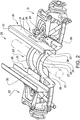
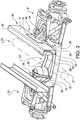
- Figs. 2 and 3 show individual suspension arrangements where the individual suspension is used.
- the shown individual suspension is a left wheel suspension.
- the individual suspension 1 comprises a lower wishbone bracket 2 and an upper wishbone bracket 3.
- the lower wishbone bracket is mounted to the lower portion of a support assembly 11, here shown as a sub-frame assembly 23 comprising two sub-frames 25, with rubber bushings.
- the lower wishbone bracket 2 is further mounted to the lower portion of a king post 4 with rubber bushings.
- On the king post a disc brake 9 and a hub 8 are arranged.
- the upper wishbone bracket 3 is mounted to the upper portion of the support assembly 11 and to the upper portion of the kingpost 4 with rubber bushings. Since the axle is of a non-steering type, the king post is provided with two attachments at the lower and upper portion.
- the wheel suspension further comprises an air bellows 6 which makes up the spring of the suspension, and a shock absorber 5.
- the lower part of the air bellows is mounted to the king post and the upper part of the air bellows bears on an upper air bellows support 12, which is preferably supplied on a frame bracket.
- the shock absorber is mounted between the king post and the upper wishbone bracket.
- the air bellows 6 is mounted in the wheel suspension such that it is positioned outside of a plane defined by the web 31 of the left main frame beam 30 of the vehicle. By positioning the air bellows outside of the frame, a more compact wheel suspension is provided.
- the left wheel suspension is also provided with a lifting bellows 7.
- a lifting bellows By using a lifting bellows, a liftable axle is obtained.
- the liftable axle may be either a pusher axle or a tag axle.
- a pusher axle is used as an example of a liftable axle.
- the lifting bellows 7 is positioned inside a plane defined by the web of the main frame beam, and inside of the air bellows. With this position, the lifting bellows is well protected. The two bellows are thus arranged along the same axle between the wheel hubs. By positioning the lifting bellows in this way, a compact pusher wheel suspension is obtained, where both the air bellows and the lifting bellows can fit between the wheel and the propeller shaft.
- neither the air bellows nor the lifting bellows extends forwards or rearwards of the wheel, which means that other components can be mounted in front of and close to the wheel.
- Such components may be e.g. a fuel tank, a storage box or a battery box.
- springs and brackets extend forwards of the wheel.
- the lifting bellows is arranged between an extension 10 of the lower wishbone bracket and an upper lifting bellows support 13, which may be comprised in a frame bracket.
- the upper lifting bellows support 13 may also be a support mounted to the support assembly 11, such as a U-link 14 mounted to the sub-frame 25.
- the air bellows of the wheel suspension is inflated, acting as the spring of the wheel suspension. In this way, an individual air suspended wheel is provided.
- the air bellows is deflated and the lifting bellows is inflated. This will push the lower wishbone extension 10 supporting the lifting bellows 7 down, and the outer end of the lower wishbone bracket will rise, which will lift the wheel from the ground.
- Fig. 2 shows a first embodiment of an individual suspension arrangement 20 according to the invention for the use in a vehicle, preferably a heavy vehicle such as a truck.
- the individual suspension arrangement 20 comprises a left individual wheel suspension 21 and a right individual wheel suspension 22.
- the left wheel suspension and the right wheel suspension are similar, but mirror-inverted, and have the same functionality. Thus, only the left wheel suspension 21 is described in detail.
- the left and right wheel suspensions are hingedly attached to a sub-frame assembly 23 which provides fixed positions for the inner attachments of the wheel suspensions. In this way, an individual wheel suspension arrangement is provided, where no rigid axle member interconnects the wheels.
- the sub-frame assembly 23 preferably consists of two sub-frames 25 which are spaced apart in order to improve the stiffness and rigidity of the individual suspension arrangement.
- each sub-frame 25 comprises two sub-frame elements 27, 28 made from pressed and cut steel sheet material.
- the two sub-frame elements may be identical or may be different, depending on the design.
- a sub-frame further comprises a sub-frame support bracket 29 which is positioned between the two sub-frame elements, close to the attachment positions for the upper and lower wishbones.
- the sub-frame support bracket helps to stabilize the sub-frame and will also make up the mounting positions 26 for the sub-frame when it is mounted to the frame bracket. It would also be possible to make a sub-frame in other materials, such as cast or forged steel.
- the individual suspension arrangement further comprises frame brackets 24 to which the sub-frame assembly of the individual suspension arrangement is mounted.
- the main frame beam 30 is a U-beam and comprises a web 31, an upper flange 32 and a lower flange 33.
- the vertical frame bracket flange 34 is mounted only to the web of the main frame beam.
- the frame bracket is mounted with a plurality of fastening means such as screws and/or rivets. The fastening means will thus hold the frame bracket to the main frame in only one mounting position 36, where the mounting position extends over a large part of the vertical flange of the frame bracket.
- the horizontal flange 35 of the frame bracket is not in contact with the lower flange 33 of the main frame beam 30.
- the complete rear suspension arrangement will be mounted to the main frame of the vehicle in only two mounting positions, one on each side of the frame.
- the advantage of this is that forces, especially lateral forces, acting on the wheel suspensions will not be transferred to the frame of the vehicle, but will instead be transferred to the sub-frame assembly and will thus act only on the rear suspension arrangement. This will reduce the influences from the wheel suspensions on the frame of the vehicle and will reduce the flexing of the frame.
- sub-frame assembly 23 of the individual suspension arrangement 20 is only mounted to the horizontal flanges 35 of the frame brackets 24.
- Each sub-frame 25 is mounted to a frame bracket in one mounting position 26.
- the bellows 6, 7 may also bear on the frame bracket. This means that all forces acting on the wheel suspensions will be transferred to the frame bracket and to the sub-frame assembly.
- the frame bracket will take up the forces but will not transfer them to the main frame.
- the impact on the fastening means which attaches the frame bracket to the web of the frame is thus reduced.
- two spaced apart brackets, a forward bracket and a rearward bracket will attach the suspension to the main frame, which will transfer the forces to and through the main frame.
- the sub-frame assembly 23 is in the shown example arc-shaped such that it extends above the propeller shaft 37 of the vehicle. In this way, there is room for the propeller shaft to move up and down when the driving wheels spring due to an uneven road or the like. In this way, the ground clearance of the vehicle is improved, which is advantageous for vehicles travelling on rough roads.
- This arrangement is especially suited for a pusher axle which is arranged in front of the drive wheels on a vehicle having more than one rear axle. Since the individual suspension does not extend forwards more than the wheel, it is possible to mount other components close to the wheels of the pusher axle, which is the first rear axle. Such components may be a fuel tank, a battery box or another storage box.
- Fig. 3 shows a development of the individual suspension arrangement 20 according to the invention.
- the individual suspension arrangement shown in Fig. 3 resembles the one shown in Fig. 2 , with the only difference being the design of the sub-frame assembly 23 and the frame bracket 24.
- the sub-frame is designed such that it can extend under a propeller shaft of a vehicle, when the arrangement is used as a pusher axle.
- Such an arrangement may be suitable for highway trucks which may not require a high ground clearance.
- the arrangement may also be used for a tag axle, where the sub-frame assembly may be designed to the required ground clearance, since there is no propeller shaft to adapt to when the axel is arranged behind the drive axle of the vehicle.
- the frame bracket 24 comprises a vertical flange 34 which is mounted to the web 31 of the main frame beam in one mounting position 36.
- the frame bracket further comprises an angled lower flange to which the sub-frame support bracket and thus the sub-frame assembly is mounted.
- each sub-frame assembly is only mounted to each frame bracket in one mounting position.
- the lifting bellows 7 does not bear on the frame bracket in is example, since the lower flange does not extend inwards such that it can provide a bearing surface for the lifting bellows. Instead, the lifting bellows 7 is supported by a U-shaped link member 14 which is attached to the sub-frame assembly, and more specifically to both sub-frames 25. In this way, the lifting bellows can apply a force between the lower wishbone bracket extension and the sub-frame assembly that will lift the wheels of the liftable axle.
- the individual suspension arrangement is mounted to the vehicle in the following way.
- the left and right wheel suspensions are preassembled at a first assembly site. Thereafter, the wheel suspensions are mounted to the sub-frame assembly.
- the wheel suspensions are held to the sub-frame assembly by rubber bushings and screws. In this way, an individual suspension arrangement comprising the sub-frame and the left and right wheel suspensions is obtained.
- the air bellows are mounted to the king posts and the lifting bellows are mounted to the extensions of the lower wishbone brackets.
- the frame brackets are mounted to the web of the main frame beams of the vehicle in the normal production flow.
- the preassembled individual suspension arrangement is docked to the frame brackets from below at a docking station and is mounted to the frame brackets at the sub-frame mounting positions 26 with e.g. screws. This allows the rear suspension arrangement to be mounted to the vehicle in an easy and quick way. Further, the rear suspension assembly can be preassembled in a reliable way.
Landscapes
- Engineering & Computer Science (AREA)
- Mechanical Engineering (AREA)
- Chemical & Material Sciences (AREA)
- Combustion & Propulsion (AREA)
- Transportation (AREA)
- Vehicle Body Suspensions (AREA)
Claims (15)
- Suspension individuelle (1) pour un essieu arrière d'un véhicule, comprenant un triangle de suspension inférieur (2) et une triangle de suspension supérieur (3), où le triangle de suspension inférieur (2) et le triangle de suspension supérieur (3) sont suspendus de manière articulée à un ensemble de support (11) et à un porte-moyeu (4), caractérisée en ce que la suspension comprend en outre un soufflet à air (6) et un soufflet de levage (7), où le soufflet à air (6) est monté sur le porte-moyeu (4) et agencé à l'extérieur d'un plan défini par une bande (31) d'une poutre de châssis principale (30), et en ce que le soufflet de levage (7) agit sur une extension (10) du triangle de suspension inférieur (2) et est agencé à l'intérieur du plan défini par la bande (31) de la poutre de châssis principale (30), ladite suspension individuelle (1) comprenant en outre un support châssis (24) monté sur la poutre de châssis principale (30), où le soufflet à air est relié à une bride verticale de support châssis (34) du support châssis (24) et le soufflet de levage est relié à une bride horizontale de support châssis (35) du support châssis (24), ladite bride horizontale de support châssis (35) étant agencée dans une configuration sans contact avec la poutre de châssis principale (30).
- Suspension selon la revendication 1, caractérisée en ce que le soufflet à air (6) est agencé entre le triangle de suspension inférieur (2) et un support de soufflet à air supérieur (12) et en ce que le soufflet de levage (7) est agencé entre l'extension du triangle de suspension inférieur (2) et un support de soufflet de levage supérieur (13).
- Suspension selon la revendication 2, caractérisée en ce que le support de soufflet à air supérieur (12) est un support châssis (24) fixé à la bande (31) d'une poutre de châssis principale (30).
- Suspension selon la revendication 2 ou 3, caractérisée en ce que le support de soufflet de levage supérieur (13) est un support châssis (24) fixé à la bande (31) de la poutre de châssis principale (30).
- Suspension selon la revendication 2 ou 3, caractérisée en ce que le support de soufflet de levage supérieur (13) est un élément de liaison en forme de U (14) monté sur l'ensemble de support (11).
- Agencement de suspension individuelle (20) pour un essieu arrière d'un véhicule, comprenant une suspension de roue gauche (21) et une suspension de roue droite (22) selon l'une des revendications 1 à 5, caractérisé en ce que l'agencement comprend en outre au moins un ensemble de châssis secondaire (23) s'étendant entre les suspensions de roue gauche et droite (21, 22), où les suspensions de roue gauche et droite (21, 22) sont montées directement sur l'ensemble de châssis secondaire (23).
- Agencement selon la revendication 6, caractérisé en ce que l'agencement comprend en outre une support châssis (24) monté sur l'ensemble de châssis secondaire (23) au niveau de chaque suspension de roue (21, 22), où le support châssis (24) est adapté pour être monté uniquement sur la bande (31) de la poutre de châssis principale (30).
- Agencement selon l'une des revendications 6 ou 7, caractérisé en ce que l'ensemble de châssis secondaire (23) comprend deux châssis secondaires (25) s'étendant entre les suspensions de roue gauche et droite (21, 22) et sont montés sur chaque côté du soufflet de levage (7) dans la direction longitudinale du véhicule.
- Agencement selon la revendication 8, caractérisé en ce que chaque châssis secondaire (25) est monté sur chaque support châssis (24) dans une seule position de montage (26).
- Agencement selon l'une des revendications 8 et 9, caractérisé en ce que chaque châssis secondaire (25) comprend deux éléments de châssis secondaire (27, 28) montés parallèlement l'un à l'autre.
- Agencement selon la revendication 10, caractérisé en ce que chaque châssis secondaire (25) comprend un support de châssis secondaire (29) enfermé entre les éléments de châssis secondaire (27, 28).
- Agencement selon la revendication 7, caractérisé en ce que le support de soufflet à air supérieur (12) et le support de soufflet de levage supérieur (13) sont compris dans le support châssis (24).
- Véhicule, comprenant au moins un agencement de suspension arrière (20) selon l'une des revendications 6 à 12.
- Véhicule selon la revendication 13, caractérisé en ce que l'ensemble de châssis secondaire (23) s'étend au-dessus de l'arbre de transmission (34) du véhicule.
- Véhicule selon la revendication 13, caractérisé en ce que l'ensemble de châssis secondaire (23) s'étend en dessous de l'arbre de transmission (34) du véhicule.
Applications Claiming Priority (1)
| Application Number | Priority Date | Filing Date | Title |
|---|---|---|---|
| PCT/SE2012/000181 WO2014074031A1 (fr) | 2012-11-07 | 2012-11-07 | Suspension arrière indépendante pourvue d'un dispositif de levage |
Publications (3)
| Publication Number | Publication Date |
|---|---|
| EP2917052A1 EP2917052A1 (fr) | 2015-09-16 |
| EP2917052A4 EP2917052A4 (fr) | 2016-09-28 |
| EP2917052B1 true EP2917052B1 (fr) | 2018-08-01 |
Family
ID=50684982
Family Applications (1)
| Application Number | Title | Priority Date | Filing Date |
|---|---|---|---|
| EP12887934.3A Active EP2917052B1 (fr) | 2012-11-07 | 2012-11-07 | Suspension arrière indépendante pourvue d'un dispositif de levage |
Country Status (3)
| Country | Link |
|---|---|
| US (1) | US9469172B2 (fr) |
| EP (1) | EP2917052B1 (fr) |
| WO (1) | WO2014074031A1 (fr) |
Families Citing this family (8)
| Publication number | Priority date | Publication date | Assignee | Title |
|---|---|---|---|---|
| GB2525670A (en) * | 2014-05-02 | 2015-11-04 | Gower College Swansea | Human-propellable vehicle |
| JP5910667B2 (ja) * | 2014-05-15 | 2016-04-27 | トヨタ自動車株式会社 | 車体前部構造 |
| US9550401B2 (en) * | 2015-04-13 | 2017-01-24 | Reyco Granning, Llc | IFS including strut pivotally secured to chassis through torque tube assembly |
| US10427738B2 (en) | 2015-06-18 | 2019-10-01 | Volvo Truck Corporation | Liftable axle suspension |
| US10926596B2 (en) | 2019-02-28 | 2021-02-23 | Arvinmeritor Technology, Llc | Suspension system |
| ES2782401A1 (es) * | 2019-03-12 | 2020-09-14 | Uro Vehiculos Espec S A | Suspension mixta mecanica-neumatica |
| JP7655505B2 (ja) | 2021-03-30 | 2025-04-02 | マツダ株式会社 | 自動車のサブフレーム構造 |
| IT202100010361A1 (it) * | 2021-04-23 | 2022-10-23 | Interactive Fully Electrical Vehicles S R L | Veicolo elettrico, con struttura perfezionata |
Family Cites Families (9)
| Publication number | Priority date | Publication date | Assignee | Title |
|---|---|---|---|---|
| US3477738A (en) * | 1968-01-16 | 1969-11-11 | Gen Motors Corp | Auxiliary road wheel assembly |
| US6789812B2 (en) | 2001-10-04 | 2004-09-14 | Featherlite, Inc. | Vehicle antisway bar |
| US6796566B2 (en) * | 2001-12-07 | 2004-09-28 | Suspension Technology, Inc. | Lift axle suspension system utilizing diaphragm chambers |
| US6957819B2 (en) * | 2003-06-20 | 2005-10-25 | Watson & Chalin Manufacturing, Inc. | Lift axle parallelogram suspension system |
| US7152866B2 (en) * | 2004-01-14 | 2006-12-26 | Watson & Chalin Manufacturing, Inc. | Steerable and liftable independent suspension system |
| US8403346B2 (en) * | 2005-01-20 | 2013-03-26 | Watson & Chalin Manufacturring, Inc. | Adjustable run height lift axle suspension system |
| US7434821B2 (en) * | 2005-05-06 | 2008-10-14 | Tuthill Corporation | Vehicle suspension with lift axle and pivotal lift spring |
| DE102006032884A1 (de) | 2006-07-15 | 2008-01-17 | Daimler Ag | Einzelradaufhängung |
| US8967639B2 (en) * | 2013-01-28 | 2015-03-03 | Saf-Holland, Inc. | Auxiliary axle and suspension assembly |
-
2012
- 2012-11-07 EP EP12887934.3A patent/EP2917052B1/fr active Active
- 2012-11-07 WO PCT/SE2012/000181 patent/WO2014074031A1/fr not_active Ceased
- 2012-11-07 US US14/440,919 patent/US9469172B2/en active Active
Non-Patent Citations (1)
| Title |
|---|
| None * |
Also Published As
| Publication number | Publication date |
|---|---|
| US9469172B2 (en) | 2016-10-18 |
| EP2917052A1 (fr) | 2015-09-16 |
| WO2014074031A1 (fr) | 2014-05-15 |
| US20150298518A1 (en) | 2015-10-22 |
| EP2917052A4 (fr) | 2016-09-28 |
Similar Documents
| Publication | Publication Date | Title |
|---|---|---|
| EP2917052B1 (fr) | Suspension arrière indépendante pourvue d'un dispositif de levage | |
| EP3241691B1 (fr) | Module de suspension comportant un ensemble de chassis auxiliaire | |
| EP1911661B1 (fr) | Sous-ensemble de suspension | |
| JP5784509B2 (ja) | 自動車用サスペンション | |
| US6736232B1 (en) | Front axle arrangement for a heavy vehicle | |
| CN106457939B (zh) | 车辆悬架 | |
| US9469173B2 (en) | Vehicle suspension | |
| CN108025612B (zh) | 用于重型车辆的锥形车轴和悬架系统梁 | |
| CN104608573A (zh) | 气囊提升桥结构板簧悬架系统和汽车 | |
| KR101315489B1 (ko) | 차량용 서브프레임의 구조 | |
| EP1888355B1 (fr) | Systemes de suspension | |
| CN210416093U (zh) | 一整体式管梁车桥装置 | |
| CN216683950U (zh) | 油气悬架用转向驱动桥桥壳 | |
| CN201071075Y (zh) | 发动机前置式三桥客车 | |
| CN201325558Y (zh) | 正三轮摩托车的后轮悬挂结构 | |
| WO2018066608A1 (fr) | Support de tourillon et suspension de type à tourillon | |
| CN219903941U (zh) | 一种钢板弹簧悬挂的驱动桥桥壳 | |
| CN112455243B (zh) | 无轨电车走行系统及无轨电车 | |
| CN112455244B (zh) | 无轨电车动力走行系统及无轨电车 | |
| CN112455489B (zh) | 应用于无轨电车的轴箱 | |
| KR100398211B1 (ko) | 자동차용 반독립 후륜 현가장치 | |
| HK1234707A1 (en) | Vehicle suspension | |
| OA18478A (en) | Conversion of a two-wheel drive vehicle to a four-wheel drive vehicle. |
Legal Events
| Date | Code | Title | Description |
|---|---|---|---|
| PUAI | Public reference made under article 153(3) epc to a published international application that has entered the european phase |
Free format text: ORIGINAL CODE: 0009012 |
|
| 17P | Request for examination filed |
Effective date: 20150605 |
|
| AK | Designated contracting states |
Kind code of ref document: A1 Designated state(s): AL AT BE BG CH CY CZ DE DK EE ES FI FR GB GR HR HU IE IS IT LI LT LU LV MC MK MT NL NO PL PT RO RS SE SI SK SM TR |
|
| AX | Request for extension of the european patent |
Extension state: BA ME |
|
| DAX | Request for extension of the european patent (deleted) | ||
| RA4 | Supplementary search report drawn up and despatched (corrected) |
Effective date: 20160831 |
|
| RIC1 | Information provided on ipc code assigned before grant |
Ipc: B62D 61/12 20060101ALI20160825BHEP Ipc: B60G 11/28 20060101ALI20160825BHEP Ipc: B62D 21/11 20060101ALI20160825BHEP Ipc: B60G 11/27 20060101AFI20160825BHEP Ipc: B60G 3/20 20060101ALI20160825BHEP |
|
| GRAP | Despatch of communication of intention to grant a patent |
Free format text: ORIGINAL CODE: EPIDOSNIGR1 |
|
| INTG | Intention to grant announced |
Effective date: 20180319 |
|
| RIN1 | Information on inventor provided before grant (corrected) |
Inventor name: SAMSON, JOHAN Inventor name: ANDERSSON, JOERGEN |
|
| GRAS | Grant fee paid |
Free format text: ORIGINAL CODE: EPIDOSNIGR3 |
|
| GRAA | (expected) grant |
Free format text: ORIGINAL CODE: 0009210 |
|
| AK | Designated contracting states |
Kind code of ref document: B1 Designated state(s): AL AT BE BG CH CY CZ DE DK EE ES FI FR GB GR HR HU IE IS IT LI LT LU LV MC MK MT NL NO PL PT RO RS SE SI SK SM TR |
|
| REG | Reference to a national code |
Ref country code: GB Ref legal event code: FG4D |
|
| REG | Reference to a national code |
Ref country code: CH Ref legal event code: EP Ref country code: AT Ref legal event code: REF Ref document number: 1023869 Country of ref document: AT Kind code of ref document: T Effective date: 20180815 |
|
| REG | Reference to a national code |
Ref country code: IE Ref legal event code: FG4D |
|
| REG | Reference to a national code |
Ref country code: DE Ref legal event code: R096 Ref document number: 602012049294 Country of ref document: DE |
|
| REG | Reference to a national code |
Ref country code: SE Ref legal event code: TRGR |
|
| REG | Reference to a national code |
Ref country code: NL Ref legal event code: MP Effective date: 20180801 |
|
| REG | Reference to a national code |
Ref country code: LT Ref legal event code: MG4D |
|
| REG | Reference to a national code |
Ref country code: AT Ref legal event code: MK05 Ref document number: 1023869 Country of ref document: AT Kind code of ref document: T Effective date: 20180801 |
|
| PG25 | Lapsed in a contracting state [announced via postgrant information from national office to epo] |
Ref country code: LT Free format text: LAPSE BECAUSE OF FAILURE TO SUBMIT A TRANSLATION OF THE DESCRIPTION OR TO PAY THE FEE WITHIN THE PRESCRIBED TIME-LIMIT Effective date: 20180801 Ref country code: RS Free format text: LAPSE BECAUSE OF FAILURE TO SUBMIT A TRANSLATION OF THE DESCRIPTION OR TO PAY THE FEE WITHIN THE PRESCRIBED TIME-LIMIT Effective date: 20180801 Ref country code: BG Free format text: LAPSE BECAUSE OF FAILURE TO SUBMIT A TRANSLATION OF THE DESCRIPTION OR TO PAY THE FEE WITHIN THE PRESCRIBED TIME-LIMIT Effective date: 20181101 Ref country code: NL Free format text: LAPSE BECAUSE OF FAILURE TO SUBMIT A TRANSLATION OF THE DESCRIPTION OR TO PAY THE FEE WITHIN THE PRESCRIBED TIME-LIMIT Effective date: 20180801 Ref country code: PL Free format text: LAPSE BECAUSE OF FAILURE TO SUBMIT A TRANSLATION OF THE DESCRIPTION OR TO PAY THE FEE WITHIN THE PRESCRIBED TIME-LIMIT Effective date: 20180801 Ref country code: FI Free format text: LAPSE BECAUSE OF FAILURE TO SUBMIT A TRANSLATION OF THE DESCRIPTION OR TO PAY THE FEE WITHIN THE PRESCRIBED TIME-LIMIT Effective date: 20180801 Ref country code: GR Free format text: LAPSE BECAUSE OF FAILURE TO SUBMIT A TRANSLATION OF THE DESCRIPTION OR TO PAY THE FEE WITHIN THE PRESCRIBED TIME-LIMIT Effective date: 20181102 Ref country code: AT Free format text: LAPSE BECAUSE OF FAILURE TO SUBMIT A TRANSLATION OF THE DESCRIPTION OR TO PAY THE FEE WITHIN THE PRESCRIBED TIME-LIMIT Effective date: 20180801 Ref country code: NO Free format text: LAPSE BECAUSE OF FAILURE TO SUBMIT A TRANSLATION OF THE DESCRIPTION OR TO PAY THE FEE WITHIN THE PRESCRIBED TIME-LIMIT Effective date: 20181101 Ref country code: IS Free format text: LAPSE BECAUSE OF FAILURE TO SUBMIT A TRANSLATION OF THE DESCRIPTION OR TO PAY THE FEE WITHIN THE PRESCRIBED TIME-LIMIT Effective date: 20181201 |
|
| PG25 | Lapsed in a contracting state [announced via postgrant information from national office to epo] |
Ref country code: LV Free format text: LAPSE BECAUSE OF FAILURE TO SUBMIT A TRANSLATION OF THE DESCRIPTION OR TO PAY THE FEE WITHIN THE PRESCRIBED TIME-LIMIT Effective date: 20180801 Ref country code: HR Free format text: LAPSE BECAUSE OF FAILURE TO SUBMIT A TRANSLATION OF THE DESCRIPTION OR TO PAY THE FEE WITHIN THE PRESCRIBED TIME-LIMIT Effective date: 20180801 Ref country code: AL Free format text: LAPSE BECAUSE OF FAILURE TO SUBMIT A TRANSLATION OF THE DESCRIPTION OR TO PAY THE FEE WITHIN THE PRESCRIBED TIME-LIMIT Effective date: 20180801 |
|
| PG25 | Lapsed in a contracting state [announced via postgrant information from national office to epo] |
Ref country code: IT Free format text: LAPSE BECAUSE OF FAILURE TO SUBMIT A TRANSLATION OF THE DESCRIPTION OR TO PAY THE FEE WITHIN THE PRESCRIBED TIME-LIMIT Effective date: 20180801 Ref country code: RO Free format text: LAPSE BECAUSE OF FAILURE TO SUBMIT A TRANSLATION OF THE DESCRIPTION OR TO PAY THE FEE WITHIN THE PRESCRIBED TIME-LIMIT Effective date: 20180801 Ref country code: CZ Free format text: LAPSE BECAUSE OF FAILURE TO SUBMIT A TRANSLATION OF THE DESCRIPTION OR TO PAY THE FEE WITHIN THE PRESCRIBED TIME-LIMIT Effective date: 20180801 Ref country code: EE Free format text: LAPSE BECAUSE OF FAILURE TO SUBMIT A TRANSLATION OF THE DESCRIPTION OR TO PAY THE FEE WITHIN THE PRESCRIBED TIME-LIMIT Effective date: 20180801 Ref country code: ES Free format text: LAPSE BECAUSE OF FAILURE TO SUBMIT A TRANSLATION OF THE DESCRIPTION OR TO PAY THE FEE WITHIN THE PRESCRIBED TIME-LIMIT Effective date: 20180801 |
|
| REG | Reference to a national code |
Ref country code: DE Ref legal event code: R097 Ref document number: 602012049294 Country of ref document: DE |
|
| PG25 | Lapsed in a contracting state [announced via postgrant information from national office to epo] |
Ref country code: SK Free format text: LAPSE BECAUSE OF FAILURE TO SUBMIT A TRANSLATION OF THE DESCRIPTION OR TO PAY THE FEE WITHIN THE PRESCRIBED TIME-LIMIT Effective date: 20180801 Ref country code: SM Free format text: LAPSE BECAUSE OF FAILURE TO SUBMIT A TRANSLATION OF THE DESCRIPTION OR TO PAY THE FEE WITHIN THE PRESCRIBED TIME-LIMIT Effective date: 20180801 Ref country code: DK Free format text: LAPSE BECAUSE OF FAILURE TO SUBMIT A TRANSLATION OF THE DESCRIPTION OR TO PAY THE FEE WITHIN THE PRESCRIBED TIME-LIMIT Effective date: 20180801 |
|
| PLBE | No opposition filed within time limit |
Free format text: ORIGINAL CODE: 0009261 |
|
| STAA | Information on the status of an ep patent application or granted ep patent |
Free format text: STATUS: NO OPPOSITION FILED WITHIN TIME LIMIT |
|
| REG | Reference to a national code |
Ref country code: CH Ref legal event code: PL |
|
| 26N | No opposition filed |
Effective date: 20190503 |
|
| GBPC | Gb: european patent ceased through non-payment of renewal fee |
Effective date: 20181107 |
|
| PG25 | Lapsed in a contracting state [announced via postgrant information from national office to epo] |
Ref country code: MC Free format text: LAPSE BECAUSE OF FAILURE TO SUBMIT A TRANSLATION OF THE DESCRIPTION OR TO PAY THE FEE WITHIN THE PRESCRIBED TIME-LIMIT Effective date: 20180801 Ref country code: LU Free format text: LAPSE BECAUSE OF NON-PAYMENT OF DUE FEES Effective date: 20181107 |
|
| REG | Reference to a national code |
Ref country code: BE Ref legal event code: MM Effective date: 20181130 |
|
| REG | Reference to a national code |
Ref country code: IE Ref legal event code: MM4A |
|
| PG25 | Lapsed in a contracting state [announced via postgrant information from national office to epo] |
Ref country code: CH Free format text: LAPSE BECAUSE OF NON-PAYMENT OF DUE FEES Effective date: 20181130 Ref country code: LI Free format text: LAPSE BECAUSE OF NON-PAYMENT OF DUE FEES Effective date: 20181130 Ref country code: SI Free format text: LAPSE BECAUSE OF FAILURE TO SUBMIT A TRANSLATION OF THE DESCRIPTION OR TO PAY THE FEE WITHIN THE PRESCRIBED TIME-LIMIT Effective date: 20180801 |
|
| PG25 | Lapsed in a contracting state [announced via postgrant information from national office to epo] |
Ref country code: IE Free format text: LAPSE BECAUSE OF NON-PAYMENT OF DUE FEES Effective date: 20181107 |
|
| PG25 | Lapsed in a contracting state [announced via postgrant information from national office to epo] |
Ref country code: BE Free format text: LAPSE BECAUSE OF NON-PAYMENT OF DUE FEES Effective date: 20181130 |
|
| PG25 | Lapsed in a contracting state [announced via postgrant information from national office to epo] |
Ref country code: GB Free format text: LAPSE BECAUSE OF NON-PAYMENT OF DUE FEES Effective date: 20181107 |
|
| PG25 | Lapsed in a contracting state [announced via postgrant information from national office to epo] |
Ref country code: MT Free format text: LAPSE BECAUSE OF NON-PAYMENT OF DUE FEES Effective date: 20181107 |
|
| PG25 | Lapsed in a contracting state [announced via postgrant information from national office to epo] |
Ref country code: TR Free format text: LAPSE BECAUSE OF FAILURE TO SUBMIT A TRANSLATION OF THE DESCRIPTION OR TO PAY THE FEE WITHIN THE PRESCRIBED TIME-LIMIT Effective date: 20180801 |
|
| PG25 | Lapsed in a contracting state [announced via postgrant information from national office to epo] |
Ref country code: PT Free format text: LAPSE BECAUSE OF FAILURE TO SUBMIT A TRANSLATION OF THE DESCRIPTION OR TO PAY THE FEE WITHIN THE PRESCRIBED TIME-LIMIT Effective date: 20180801 |
|
| PG25 | Lapsed in a contracting state [announced via postgrant information from national office to epo] |
Ref country code: HU Free format text: LAPSE BECAUSE OF FAILURE TO SUBMIT A TRANSLATION OF THE DESCRIPTION OR TO PAY THE FEE WITHIN THE PRESCRIBED TIME-LIMIT; INVALID AB INITIO Effective date: 20121107 Ref country code: MK Free format text: LAPSE BECAUSE OF NON-PAYMENT OF DUE FEES Effective date: 20180801 Ref country code: CY Free format text: LAPSE BECAUSE OF FAILURE TO SUBMIT A TRANSLATION OF THE DESCRIPTION OR TO PAY THE FEE WITHIN THE PRESCRIBED TIME-LIMIT Effective date: 20180801 |
|
| PGFP | Annual fee paid to national office [announced via postgrant information from national office to epo] |
Ref country code: FR Payment date: 20241126 Year of fee payment: 13 |
|
| PGFP | Annual fee paid to national office [announced via postgrant information from national office to epo] |
Ref country code: DE Payment date: 20251126 Year of fee payment: 14 |
|
| PGFP | Annual fee paid to national office [announced via postgrant information from national office to epo] |
Ref country code: SE Payment date: 20251124 Year of fee payment: 14 |