EP2917457B1 - Appareil à marteau soutenu destiné au carottage - Google Patents
Appareil à marteau soutenu destiné au carottage Download PDFInfo
- Publication number
- EP2917457B1 EP2917457B1 EP13852635.5A EP13852635A EP2917457B1 EP 2917457 B1 EP2917457 B1 EP 2917457B1 EP 13852635 A EP13852635 A EP 13852635A EP 2917457 B1 EP2917457 B1 EP 2917457B1
- Authority
- EP
- European Patent Office
- Prior art keywords
- core
- hammer
- impact
- bit
- assembly
- Prior art date
- Legal status (The legal status is an assumption and is not a legal conclusion. Google has not performed a legal analysis and makes no representation as to the accuracy of the status listed.)
- Active
Links
Images

Classifications
-
- E—FIXED CONSTRUCTIONS
- E21—EARTH OR ROCK DRILLING; MINING
- E21B—EARTH OR ROCK DRILLING; OBTAINING OIL, GAS, WATER, SOLUBLE OR MELTABLE MATERIALS OR A SLURRY OF MINERALS FROM WELLS
- E21B25/00—Apparatus for obtaining or removing undisturbed cores, e.g. core barrels or core extractors
- E21B25/10—Formed core retaining or severing means
-
- E—FIXED CONSTRUCTIONS
- E21—EARTH OR ROCK DRILLING; MINING
- E21B—EARTH OR ROCK DRILLING; OBTAINING OIL, GAS, WATER, SOLUBLE OR MELTABLE MATERIALS OR A SLURRY OF MINERALS FROM WELLS
- E21B10/00—Drill bits
- E21B10/02—Core bits
-
- E—FIXED CONSTRUCTIONS
- E21—EARTH OR ROCK DRILLING; MINING
- E21B—EARTH OR ROCK DRILLING; OBTAINING OIL, GAS, WATER, SOLUBLE OR MELTABLE MATERIALS OR A SLURRY OF MINERALS FROM WELLS
- E21B25/00—Apparatus for obtaining or removing undisturbed cores, e.g. core barrels or core extractors
-
- E—FIXED CONSTRUCTIONS
- E21—EARTH OR ROCK DRILLING; MINING
- E21B—EARTH OR ROCK DRILLING; OBTAINING OIL, GAS, WATER, SOLUBLE OR MELTABLE MATERIALS OR A SLURRY OF MINERALS FROM WELLS
- E21B25/00—Apparatus for obtaining or removing undisturbed cores, e.g. core barrels or core extractors
- E21B25/02—Apparatus for obtaining or removing undisturbed cores, e.g. core barrels or core extractors the core receiver being insertable into, or removable from, the borehole without withdrawing the drilling pipe
-
- E—FIXED CONSTRUCTIONS
- E21—EARTH OR ROCK DRILLING; MINING
- E21B—EARTH OR ROCK DRILLING; OBTAINING OIL, GAS, WATER, SOLUBLE OR MELTABLE MATERIALS OR A SLURRY OF MINERALS FROM WELLS
- E21B6/00—Drives for drilling with combined rotary and percussive action
-
- E—FIXED CONSTRUCTIONS
- E21—EARTH OR ROCK DRILLING; MINING
- E21B—EARTH OR ROCK DRILLING; OBTAINING OIL, GAS, WATER, SOLUBLE OR MELTABLE MATERIALS OR A SLURRY OF MINERALS FROM WELLS
- E21B6/00—Drives for drilling with combined rotary and percussive action
- E21B6/02—Drives for drilling with combined rotary and percussive action the rotation being continuous
- E21B6/04—Separate drives for percussion and rotation
Definitions
- the present disclosure relates to core sampling of ground formations in general.
- the disclosure is also for a novel core sampling impact apparatus and related apparatus, systems, and methods and uses.
- the core barrel is usually 1.5 -3 metres long.
- a latching tool is lowered on a wire line from surface inside the drill rods (casing).
- the latching tool attaches to the core barrel and as it is pulled from the inside of the drill rods (casing) the lower end of the core barrel snags hold of the rock core breaking it from the rock formation and the entire assembly is pulled to surface for core recovery.
- the drill rods (casing) stay in the ground forming a temporary casing which prevents the bore hole from collapsing.
- the core barrel etc. is then lowered back down inside the drill rods (casing) and the process continues until the required depth of core has been recovered. While this system works well it is expensive and relatively slow. In addition the diamond impregnated core bits, which work by abrading the rock are expensive, relatively fragile and are often damaged if too much weight is applied (pushed too hard) or if there is a change in the formation being drilled.
- Tibussek US patent 4,279,315 describes a wire line retrievable core sampling device which uses a rotating cam arrangement to apply low frequency - low force impact to a non-rotating core sampling barrel. This mechanism by its very nature precludes its ability to drill (rotate and therefore penetrate) hard rock when core sampling. Additionally this cam impacting arrangement is not able to generate the considerable forces required for crushing and therefore penetrating hard formations.
- Sweeny US patent 3854539 describes a wire line retrievable hammer which unlike Tibussek uses pressurised drilling fluid to energise a piston which transfers energy to a core sampling bit.
- this mechanism is flawed as there is no method for securely locking the hammer to the outer casing which therefore stops the tool from delivering sufficient impact force to the bit and therefore the rock. Instead the hammer bounces within the outer housing as the hammer blows are delivered.
- the core sample is not protected from the axial impact movement of the coring hammer - which testing has shown to damage or destroy otherwise valuable core samples.
- US4002213 relates to a down-the-hole motor which is adapted to be used to drive a rotary drill rod.
- DE3200927 relates to a method and a device for extracting drill cores that are distinguished by a double core barrel which consists of an outer barrel provided with a drill bit and a hinged inner barrel intended for accommodating the drill bit.
- US3854539 describes an apparatus having a rotary drill rod comprising an elongated pipe having a longitudinally extending bore therethrough and a percussive bit at the distal end thereof.
- the present invention provides a core sampling apparatus as set out in the appended claims.
- a small diameter hammer of any type such as air, fluid, magnetic, electromagnetic, or a mud motor (PDM) oscillator can be lowered inside the drill rods (casing) and seated inside the assembly so that when activated the hammer impacts upon a core bit and allows for faster core sampling and/or protects the core sample itself.
- PDM mud motor
- the present disclosure describes a core sampling apparatus that will satisfy one or more and preferably most or all of such capabilities and/or those listed below.
- a core sampling assembly/apparatus would have one or more (most preferably all) of the following capabilities:
- Examples disclosed herein can use conventional impact type bits with carbide or diamond impact bits (or similar) but with the centre removed to leave a rock core intact. These bits are very durable, are not easily damaged by a change in formation or by excessive weight on bit - and in addition they only require slow rotation (typically less than 100 RPM) meaning that specialised high speed diamond core rigs are not required.
- the disclosure relates to a core sampling apparatus to allow the capture and retrieval of a core from a subterranean formation, the apparatus comprising or including: a rotatable tubular housing, a core taking bit constrained to rotate with the housing yet able to move axially with respect to the rotatable tubular housing, a retrievable core sampling assembly latchable to the rotatably tubular housing comprising: a core catcher barrel for a core, the barrel being rotationally isolated from the tubular housing and cooperable with the core taking bit to retain a core, and a hammer for providing impact to the core taking bit along a longitudinal impact path that is or is substantially decoupled from the core catcher barrel, wherein the tubular housing is operable to rotate the bit and the hammer is operable to impact the bit to capture and pass core material from the formation to the core catcher barrel in manner that isolates a core in the core catcher barrel from rotation and impact forces.
- the longitudinal impact path comprises an impact tube or structure surrounding the core catcher barrel that receives impact from the hammer at a first end and bears against the core taking bit at another end to transfer the impact.
- the core taking bit is splined to the rotatable tubular housing to rotationally constrain the core taking bit yet enable it to move axially, and upon receiving an impact, the core taking bit moves axially with respect to the rotatable tubular housing.
- the retrievable core sampling assembly is latchable to or relative to the rotatable tubular housing using a latching assembly that latches the assembly to the rotatably tubular housing.
- a compliant member is provided between the latching assembly and the hammer to hold the hammer directly or indirectly on the bit, yet during hammer operation restrict stress on the latching assembly to maintain latching of the assembly to the rotatable tubular housing.
- the hammer is actuated by drilling fluid, wherein the drilling fluid exhausts between the core catcher barrel and impact tube or structure that surrounds the core catcher barrel and through the core taking bit thus bypassing a core in the core catcher barrel.
- the hammer comprises a rotor that upon rotation generates longitudinal movement in an impact member that provides the impact to the core taking bit, wherein the rotor is coupled via a swivel joint to the core catcher barrel so that the barrel can be retracted yet is rotationally decoupled from the rotor to isolate a core in the catcher barrel from rotation forces.
- the hammer is a magnetic hammer
- the rotor is an inner magnetic array that rotates relative to an outer magnetic array that is the impact member, wherein the inner magnetic array is coupled via the swivel joint to the core catcher barrel so that the barrel can be retracted yet is rotationally decoupled from the rotor to isolate a core in the catcher barrel from rotation forces.
- the latching assembly, compliant member, hammer, and core catcher barrel of the core sampling assembly are coupled so that they can be inserted into the rotatable tubular housing and latched to or relative to the rotatable tubular housing and retrieved from the rotatable tubular housing by delatching the latching assembly and removing the core sampling assembly using a wire latch.
- a retrievable core sampling assembly for latching to or relative to a rotatable tubular housing of a core sampling apparatus to allow the capture and retrieval of a core from a subterranean formation
- the assembly comprising or including: a core catcher barrel for a core, the barrel being rotationally isolated from the tubular housing and cooperable with a core taking bit coupled to the rotatable tubular housing to retain a core, and a hammer for providing impact to the core taking bit along a longitudinal impact path that is or is substantially decoupled from the core catcher barrel, so that when latched, rotation and impact of the core taking bit captures and passes core material from the formation to the core catcher barrel in manner that isolates a core in the core catcher barrel from rotation and impact forces.
- Also disclosed is a method of obtaining a core sample comprising using an apparatus/assembly of any preceding paragraph and operating the apparatus/assembly to rotate and hammer a bit in a manner to isolate the core from rotation and impact forces.
- Also disclosed is a method of obtaining a core sample comprising using an apparatus/assembly of any preceding paragraph and operating the apparatus/assembly to rotate and hammer a bit in a manner to isolate the core from rotation and impact forces.
- Described herein is a core sampling apparatus to allow the capture and retrieval of a core from a subterranean formation, the apparatus comprising or including
- Described herein is a core sampling apparatus to allow the capture and retrieval of a core from a subterranean formation, the apparatus comprising or including
- the bit is splined to the housing.
- interposed between the retrievable assembly and the housing is at least one member to transfer the hammer impact to the bit.
- said at least one member is a tube.
- the tube is not withdrawable uphole with the retrievable assembly.
- the hammer arrangement is a magnetic hammer arrangement.
- the magnetic hammer arrangement has a hammer mass to rotate with the housing and carrying an outer array of magnets and an inner assembly carrying an inner array of magnets able to be fluid driven to rotate relative to the hammer mass and housing.
- the inner assembly is swivel connected to said core catcher.
- a PDM empowers the magnetic hammer arrangement.
- the hammer arrangement is other than a magnetic hammer arrangement.
- the hammer arrangement is empowered (e.g. as if a piston) by a fluid or gas downflow.
- the hammer arrangement exhausts fluid from one or more outlets. Between the outer housing and the core catcher so as to not damage the core sample and the fluid exits into the bore hole via the core bit - to assist with drill cutting evacuation etc.
- the hammer arrangement is swivel connected to said core catcher, to help minimise any rotational damage from being imparted to the core sample.
- the hammer arrangement is not required to rotate with the housing.
- Described herein is a downhole apparatus comprising or including
- Described herein is a withdrawable assembly comprising or including
- Described herein is the use in conjunction with a retrievable core catching and a rotatable drillstring casing within which the core catcher is located in use of both
- a core receiving and retrieving assembly for use or suitable for use downhole within a rotatable drillstring casing having a hammerable core taking bit captive to rotate with the casing yet move axially with respect thereto, the assembly comprising or including
- an assembly insertable downhole into a drillstring casing having a core taking impact bit comprising or including: a hammer mechanism, a core catcher associated with but not to be hammered by the hammer mechanism, and a hammer impact transfer tube upliftable with the hammer mechanism and core catcher yet axially movable with respect to the core catcher and able to be both endwise hammered and to endwise impact the impact bit in use.
- the hammer mechanism is swivel connected to the core catcher.
- a releasable latching system whereby the assembly can be held from upward movement during hammering.
- Preferably it has a shock absorber or shock spreader to protect the latching system against uphole shock.
- a wire line or the equivalent retrievable core sampling hammer system (the hammer mechanism can be of any type such as pneumatic or fluid driven, magnetic hammer, electromagnetic, or any other that imparts an impact directly or indirectly to the core sampling drill bit, which causes the core sampling bit to advance into the formation being sampled), but in its most preferred forms have the attributes discussed below.
- spring includes any resilient system able to prevent or at least reduce an uphole momentary shock loading of the withdrawable systems engagement at the latching zone. It may be of a single member or a plurality of members able, over a contacting zone, to spread in time and thus momentary magnitude the shock loading away through the latching system loads.
- the "spring” may couple to an energy absorption system (e.g. damper) or not [preferably not if the "spring” is sufficiently tuned to be in phase to the cycling of the associated hammer].
- a spring may be one or more members of metal [e.g. a helical metal spring or a series of disc spring elements]. It can be of a non-metal [e.g. a suitable synthetic rubber]. It can be pneumatic.
- the spring or compliant system preferably acts to buffer with or without damping.
- grid or any other term referring to an arrangement to engage a core in the receiver and/or bit (the “tooling”) can be of any suitable type. Preferably it is a self-deploying wedge based arrangement whether of a split ring or of individually captive sliding members.
- core catcher barrel As used herein "core catcher barrel”, “core receiver” or “barrel” preferably incorporates a “gripper”.
- magnetic As used herein reference to “magnetic”, “magnetic arrays”, “magnetic hammer” includes, but is not restricted to, those devices, apparatus, systems as in downhole hammers of the type disclosed in PCT/NZ2008/000217 (published as WO2009/028964 ) and PCT/IB2012/050875 .
- downhole in respect of any apparatus, system or the like does not exclude when any such apparatus is not actually downhole.
- the term refers to its intended purposes and/or when in situ for use at the bottom end of a drillstring.
- fluid includes liquid(s), liquid systems [e.g. slurry, drilling mud etc], liquid/gas mixtures, gas or gas mixtures. Its use alongside any reference to pneumatics or gas is not restrictive of its scope.
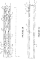
- Figures 1A to 1C show a magnetic hammer core sampling apparatus/assembly according to one embodiment of the invention, incorporated or for incorporation into a drilling apparatus 40.
- the term "core sampling apparatus” can refer to an apparatus comprising or incorporated into a drilling apparatus for core sampling, or an apparatus separate to but for incorporation into a drilling apparatus to give the drilling apparatus core sampling capability - the term should be considered broadly to cover both options.
- the term “core sampling assembly” is nominally used to refer to an apparatus for insertion/incorporation into a drilling apparatus
- the term “core sampling apparatus” is nominally used to refer to the apparatus created when a core sampling assembly is inserted/incorporated into a drilling apparatus. But, the terms should not be interpreted restrictively and, the core sampling assembly inserted into a drilling apparatus could alternatively be referred to a core sampling apparatus by someone skilled in the art.
- Figures 1A to 1C depict the same contiguous apparatus, but split into three separate drawings for purposes of magnifying details.
- the left end of Figure 1A connects to a drill rig and is uphole; the right hand end of Figure 1A follows directly to the left end of Figure 1B and the right end of Figure 1B follows directly to the left end of Figure 1C .
- the right end of Figure 1C is downhole near the bore face (when in use).
- the left direction in the drawings is uphole, and the right direction is downhole.
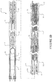
- Figure 1D shows the full apparatus, including drilling fluid flow 75 though the apparatus.
- the apparatus is for taking core samples in a manner that protects the core sample.
- the drilling apparatus 40 comprises an outer drill housing 1 (also termed “drillstring” or “drill rod” or “casing”) coupled to a core taking impact bit (“drill bit” or “core (taking) bit”) 2 ( Figure 1C ).
- Examples disclosed herein can use conventional impact type bits with carbide or diamond impact bits (or similar) but with the centre removed to leave a rock core intact. These bits are very durable, are not easily damaged by a change in formation or by excessive weight on bit - and in addition they only require slow rotation (typically less than 100 RPM) meaning that specialised high speed diamond core rigs are not required.
- the drill housing 1 can be rotated from the surface by a drill rig (known to those skilled in the art), which in turn rotates the drill bit 2 allowing for drilling of a bore and advancement into a formation in the usual manner.
- the housing thus becomes or is a "rotatable tubular housing".
- the drill bit 2 has cutting components which cut material from the formation bore face of the bore.
- the drill bit 2 has an outer casing 2a that couples by rotationally splining 20 to the outside of the rotatable tubular housing 1 so that it is constrained to rotate with the housing 1, but also so that it can move longitudinally/axially (left and right in the Figures) relative to the rotatable housing 1 for hammer purposes.
- a core sampling assembly is incorporated into the rotatable housing 1 of the drilling apparatus 40 to hammer the drill bit 2, collect a core sample 19, and enable withdrawal of the core sample 19.
- the core sampling assembly in the drilling apparatus 40 creates a core sampling apparatus 40 as explained above for capture and retrieval of a core from a subterranean formation.
- the core sampling assembly is retrievable from the drilling apparatus so that the core is retrievable.
- the core sampling assembly comprises a hammer 100 that oscillates or otherwise shuttles (left/right in the Figures) between two longitudinal (axial) positions in the drill housing 1 to provide uphole and downhole strokes (left/right in Figures) that hammer the drill bit 2.
- the core sampling assembly has a magnetic hammer ("shuttle") arrangement 100 and so takes the form of a magnetic hammer core sampling assembly, although other core sampling assemblies with other types of hammer arrangements could be used, such as shown air, fluid, magnetic, electromagnetic, or a mud motor (PDM) driven hammer arrangements.
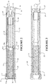
- Figures 2 and 3 show another hammer arrangement.
- the (magnetic hammer) core sampling assembly comprises an overshot system 3 used to lower and retrieve the core sampling assembly (including the hammer) of the core sampling apparatus from the drilling apparatus.
- a latch assembly 4 that couples/latches the core sampling assembly to or relative to the housing.
- the latch assembly 4 comprises extendible latch arms 5 (e.g. spring loaded latches) that engage with a shoulder 6 in the drill housing 1 that provides an abutment shown on the inside diameter of the drill housing 1.
- the latch assembly 4 constrains the magnetic hammer 100 of the apparatus (to be described below) from the upward axial movement or rebound from impacts made from the hammer 100, resulting in a focusing of all or substantially all or at least a major part of the impact force from the hammer 100 into the formation being cored.
- a positive displacement motor (PDM) 8 driven by drilling mud or similar is coupled beneath the latch assembly 4.
- PDM positive displacement motor
- Pump in seals 9 are provided that can be usefully engaged in non-vertical core sampling. Thus drilling fluid can be used to pump the assembly into place and help seat the latch assembly to enable the non-vertical core samples to be obtained.
- the PDM output shaft 11 extends downhole from the PDM 8 and through a bearing section provided below the PDM 8 comprising a bearing housing 10 and bearings 10a-10d that help support the rotating PDM output shaft 11.
- the PDM output shaft 11 is coupled at 53 to a hammer rotor input shaft 54 by a splined, threaded or other suitable coupling. (Note, the hammer rotor input shaft 54 could just be considered to be part of the output shaft 11 and the distinction of whether these are the same or different components is not critical to the invention).
- the hammer rotor input shaft 54 extends through the centre of a spring 13 (or other compliant component) that sits inside the rotatable tubular (drill) housing 1 with sufficient clearance so that as the shaft 54 rotates, it does not contact the spring.
- a first uphole end of the spring 8 is threadedly or otherwise coupled 83 to the bearing assembly 10 and a second downhole end is threadedly or otherwise coupled 80 to the magnetic hammer 100.
- the spring 13 is used to cushion the uphole force from the magnetic hammer 100 as it returns to the top of its stroke during shuttling, therefore reducing stresses on the latch arms 5 and shoulder 6 of the latch assembly 4.
- the housing 1 preferably comprises thin walled drill rods. This means that the latching assembly only has a small cross sectional abutment area to lock against. Substantial impact forces could compromise latching. As such, the spring or other compliant component helps cushion the uphole shock from hammering.
- the spring 13 or other compliant component a) reduces uphole damping, which could otherwise damage uphole components; b) helps to recapture some of the kinetic energy which is otherwise lost during shuttling; and/or c) enables a more stable shuttle oscillation. Without the spring 13, the latch arms 5 and shoulder 6 might not survive the uphole force from the hammer 100. It is not essential for operation that the spring 13 is coupled as described above (for example, it could simply bear against these components), although it is preferable as otherwise the shuttle oscillations and the spring life and fatigue are less controllable.
- the magnetic hammer 100 is downhole from the output shaft 11 and spring 13. It has an outer hammer body 61 (see Figure 4 ), inner magnetic array 15 and an outer magnetic array 14.
- the inner magnetic array (magnetic rotor) 15 is coupled to the hammer rotor input shaft 54.
- the output shaft 11 via the hammer rotor input shaft 54 rotates the inner magnetic array 15 relative to the outer magnetic array 14.
- the outer magnetic array does not rotate (with reference to the inner rotating magnetic array 15) - that is rotationally constrained by being splined 74 directly or indirectly to the impact transfer tube 16.
- the outer magnetic array is rotationally constrained and oscillates back and forth (uphole/downhole or left/right in Figures) longitudinally/axially within the housing 1.
- the outer magnetic array 14 is coupled to an impact (transfer) tube 16 or other suitable structure, for example by a threaded connection 74 either directly or via a magnetic shuttle 60 (see Figure 4 ).
- the impact transfer tube 16 sits within the outer rotatable housing 1 and has a hollow interior.
- the annular downhole end of the impact transfer tube 16 during operation can bear/abut/collide against the drill bit 2 within the drill bit casing 2a.
- a core catcher barrel 18 sits within the impact transfer tube (or other structure) 16 such that the impact tube or other structure surrounds the barrel 18. It has an opening downhole that sits adjacent the back of the drill bit 2 such that it is cooperable with the drill bit 2 to receive (core) material excavated by the drill bit. As the drill bit rotates and impacts the formation at the bore face, it excavates material which is captured in the core catcher barrel 18 resulting in a core sample 19. The core catcher barrel 18 is decoupled from the impact transfer tube 16 so it is independent from any longitudinal movement of the impact transfer tube 16. Keeping the core catcher barrel 18 longitudinally stationary isolates the core 19 therein from impact forces and is helpful in avoiding damaging the core sample.
- the outer magnetic array 14 provides impact/hammering to the core taking bit 2 directly or indirectly along a longitudinal/axial impact path (through the impact tube 16 or other structure that surrounds the core catcher barrel 18) that is decoupled (or substantially decoupled) from the core so that the impact force bypasses the core. This protects the core 19.
- a swivel section 17 couples the magnet hammer 100 (and in particular the rotor thereof) to the core catcher barrel 18 and core sample 19.
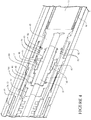
- the swivel is shown in more detail in Figure 4 . It has a swivel housing 41 that is coupled (e.g. by threaded coupling 42) to the magnetic hammer rotor 54/inner array 15, so that the housing 41 and rotor 54/inner array 15 rotate together.
- a rotationally isolated inner member 43 is disposed coaxially within the swivel housing 41. The inner member 43 is coupled (e.g. via threaded coupling 44) to an upper extension 45 from the core catcher barrel 18.
- Bearing surfaces 46 allow the swivel housing 41 to rotate independently of the inner member 43/core catcher 18/upper extension 45, and keep the inner member 43 rotationally stationary.
- the bearing surfaces 46 could be any suitable bearing material, such as PCM, plastic brush, or roller.
- the bearing surfaces 46 are retained in place by an annular plug 47 that couples (e.g. threaded coupling 48) to the swivel housing 41.
- O-rings 49 are provided on the core catcher barrel upper extension 45 to provide friction to assist in keeping the core catcher barrel 18 rotationally isolated.
- Wiper seals 50 are provided on the upper extension to keep contaminants (such as drilling fluid, etc.) out of the bearings.
- An internal axial cavity 51 in the inner magnetic array 15, inner member 43 and upper extensions 45 provide a pathway for drilling fluid 75, which will be explained in more detail later.
- An internal spline 14a is provided on the magnetic shuttle 60 and the internal spline mates to the outer hammer body 61 to stop the outer magnet array 14 from rotating, therefore causing axial movements.
- This swivel 17 enables the core catcher barrel 18 and sample 19 to be retracted from the drilling apparatus (rotatable housing 1) upon removal of the core sampling assembly using the overshot system 3, yet still allow the core catcher barrel 18 to remain rotationally stationary (that is, rotationally decoupled from the rotor to isolate a core in the barrel from rotation forces). Keeping the core catcher barrel 18 rotationally stationary is helpful to avoid damaging the core sample. Isolating the core sample 19/core catcher barrel 18 from the rotational forces of the assembly (necessary to advance the drill bit 2) is achieved using the mechanical swivel 17.
- the core drilling apparatus 40 works in the following manner.
- the core sampling assembly comprising with the overshot system 3, PDM 8, spring 13, magnetic hammer 100, swivel 17, core catcher barrel 18 and impact transfer tube 16 is inserted into the rotatable housing 1 and positioned (optionally using drilling fluid) so that the impact transfer tube 16 sits against the back of the drill bit 2/anvil 72.
- the extendable latch arms 5 engage in the shoulder 6 to retain the apparatus in place in the drill housing 1.
- the drilling rig puts weight on bit and rotates the drill housing, which rotates the splined drill bit 2 to drill into the formation.
- Drilling fluid 75 is pumped (see Figure 1D ) into the assembly around the outside of the overshot system 3 and through the fluid ports 7 to the PDM.
- the fluid rotates the PDM 8 causing the PDM output shaft 11 to rotate, which, via the hammer rotor input shaft 54, turns the inner magnetic array rotor 15.
- the magnetic interaction between the inner magnetic array 15 and outer magnetic array 14 causes longitudinal movement in the outer magnetic array 14/shuttle 61 thus oscillating/moving/impacting the impact transfer tube 16 that is threadedly coupled 74 to the outer magnetic array 14.
- the weight on bit, rotation of the drill bit 2 and hammering of the drill bit 2 excavates material into the core catcher barrel 18 and advances the drill bit 2. In order for the drill bit to advance into hard formations, it has:
- the drilling fluid passes through the PDM, centre of the hammer 100, through the swivel and then is diverted so that it exits/exhausts 75 to and out the bit 2 between the impact transfer tube 16 and the core catcher barrel 18.
- the fluid 75 when exiting the bit 2 removes cuttings from the bore face and transfers them upwardly out of the bore around the annulus between the drill bit 2 and outer drill rod 1 - as well as cooling the bit, stabilising the formation and providing lubricants to help reduce rotational torque.
- the redirection of the drilling fluid 75 achieves the following: delivers the required hydraulic forced to rotate the PDM 8 and energises the hammer 100; clears the drill cuttings from the bore and carries some out of the bore hole; cools the drill bit; and provides lubrication to the entire assembly.
- the drilling fluid 75 does not come into contact with the core sample 19 - it travels to the drill bit 2 between the impact transfer tube 16 and the core catcher barrel 18.
- the overshot system 3 is operated (in a manner known to those skilled in the art) to remove core sampling assembly from the rotatable housing 1 to retrieve the core catcher barrel 18 and the core sample 19.
- the upper end of the overshot is lowered on a wire cable inside the housing until it latches onto the top end of overshot 3 ( Fig 1a ).
- the overshot 3 retracts the spring loaded arms that had engaged with abutment 6 allowing the wire cable to pull the entire assembly to the surface (all that is left down hole is the housing and drill bit).
- the impact zone is shown in region 71/72. It will be appreciated that this impact zone can be at any point between the magnetic hammer 100 and the drill bit 2.
- this impact zone can be at any point between the magnetic hammer 100 and the drill bit 2.
- the core sampling apparatus could utilise other hammer types such as pneumatic or fluid hammers, using pressurised fluid or compressed air to energise the hammer assembly could replace the magnetic hammer section 100 to allow successful core sampling.
- hammer types such as pneumatic or fluid hammers
- pressurised fluid or compressed air to energise the hammer assembly could replace the magnetic hammer section 100 to allow successful core sampling.
- the choice of the hammer itself is not so important, as various hammer mechanisms have been used for many years and a detailed explanation of how they work is not warranted.
- a core sampling apparatus/assembly according to the disclosure is one that has the attributes 1-6 listed below.
- FIGS 2 and 3 show an alternative embodiment of a core sampling apparatus/assembly that utilises a different type of hammer 38, in this case a hydraulic hammer.
- the core sampling assembly is incorporated into a drill housing 1, such as previously described in relation to Figure 1 although details will be briefly described again.
- the core sampling assembly comprises an overshot system 33 that is coupled to a latch assembly 27, and the latch assembly has extendable arms that are coupled to a shoulder 29 in the housing 1.
- a spring 28 is provided that bears against the latch assembly 27 and a hydraulic hammer arrangement 38.
- the hammer arrangement 38 has shoulders 38a that correspond to the uphole annular surface 23a of a hollow impact transfer tube 23.
- a core catcher barrel 22 sits inside the impact transfer tube 23 in a rotational and slidably independent/isolated/decoupled manner.
- the downhole open end of the core catcher barrel 22 sits behind the drill bit 24 to capture core material that is excavated by the drill bit 24.
- the drill bit 24 is coupled to the drill housing 1 and rotationally splined in a manner as described in relation to the embodiment of Figure 1 .
- the downhole annular surface 23b of the impact transfer tube bears/abuts/collides against the inside of the drill bit 24.
- the core sampling assembly comprising the overshot system 33, hammer 38, core catcher barrel 22 and impact transfer tube 23 is inserted into the rotatable housing 1 and positioned so that the impact transfer tube 23 sits against the back of the drill bit 24.
- the extendable latch arms engage in the shoulder 29 to retain the apparatus in place in the housing 1.
- the drilling rig puts weight on bit and rotates the housing 1, which rotates the splined drill bit 2 to drill into the formation at the bore face.
- Drilling fluid 75 energises the hammer 38 with its hammer mass to coerce the hammer mass towards the impact transfer tube 23.
- the shoulders on the hammer 38a impact against the uphole annular surface 23a of the impact transfer tube 23 at an impact zone. This causes the impact transfer tube 23 to impact against the drill bit 24.
- the weight on bit, rotation of the drill bit 24 and hammering of the drill bit 2 excavates material into the core catcher barrel 22 and advances the drill bit 2.
- drilling fluid exhausts 75 between the core catcher 22 and the impact transfer tube 23 and exits at 25 from the bit 24. Some fluid is also allowed to escape at 26 in the hammer impact zone to help reduce the fluid damping the impact force.
- the hammer is held in place during impact by the latch assembly 27.
- the spring 28 allows the latch assembly 27 and shoulder 29 (small cross sectional abutment) to survive and reduces the stress on the drill rod 30 above the latch assembly.
- the core sample 21 is protected from mechanical damage (both impact and rotary).
- the core 21 is housed within the core catcher assembly 22, which is isolated from the impact transfer tube 23.
- the drill bit 24 is splined at 31 to the drill housing 30, allowing the impact force to be transferred via impact transfer tube 23 from the hammer mass via the bit 24 to the formation - without damaging the drill housing 30.
- the rotary swivel joint 32 allows the captured core 21 to be rotationally static.
- the overshot system 3 is operated to remove core sampling assembly from the drill housing 1 to retrieve the core catcher barrel and the core sample.
- the hammer assembly and core 21 are pulled to surface by a wire latching mechanism which is attached to the overshot 33. Once the core is removed at the surface the hammer and core catcher assembly is again lowered down hole.
Landscapes
- Engineering & Computer Science (AREA)
- Geology (AREA)
- Life Sciences & Earth Sciences (AREA)
- Mining & Mineral Resources (AREA)
- Environmental & Geological Engineering (AREA)
- Fluid Mechanics (AREA)
- Physics & Mathematics (AREA)
- General Life Sciences & Earth Sciences (AREA)
- Geochemistry & Mineralogy (AREA)
- Mechanical Engineering (AREA)
- Sampling And Sample Adjustment (AREA)
- Earth Drilling (AREA)
- Investigation Of Foundation Soil And Reinforcement Of Foundation Soil By Compacting Or Drainage (AREA)
Claims (9)
- Appareil de carottage pour permettre la saisie et l'extraction d'une carotte à partir d'une formation souterraine, l'appareil comprenant ou comportant :un boîtier tubulaire rotatif (1),un trépan de prélèvement de carotte (2, 24) contraint à tourner avec le boîtier tout étant capable de se déplacer axialement par rapport au boîtier tubulaire rotatif,un ensemble de carottage amovible pouvant être verrouillé (4, 5, 6) au boîtier tubulaire rotatif (1) comprenant :un cylindre extracteur de carotte (18, 22) pour une carotte (19, 21), le cylindre extracteur de carotte (18, 22) étant isolé en rotation du boîtier tubulaire (1) et pouvant coopérer avec le trépan de prélèvement de carotte (2) pour retenir une carotte (19, 21), etun marteau (38, 100) pour fournir un impact au trépan de prélèvement de carotte (2) le long d'un trajet d'impact longitudinal qui est ou est sensiblement découplé du cylindre extracteur de carotte (18, 22),dans lequel le boîtier tubulaire (1) peut fonctionner pour faire tourner le trépan (2, 24) et le marteau (38, 100) peut fonctionner pour percuter le trépan (2) afin de saisir et faire passer un matériau de carotte de la formation au cylindre extracteur de carotte (18, 22) de manière à isoler une carotte (19, 21) dans le cylindre extracteur de carotte (18, 22) des forces de rotation et d'impact.
- Appareil de carottage selon la revendication 1, dans lequel le trajet d'impact longitudinal comprend un tube (16, 23) ou une structure d'impact entourant le cylindre extracteur de carotte (18, 22) qui reçoit un impact à partir du marteau (38, 100) au niveau d'une première extrémité et s'appuie contre le trépan de prélèvement de carotte (2, 24) au niveau d'une autre extrémité pour transférer l'impact.
- Appareil de carottage selon la revendication 1 ou 2, dans lequel le trépan de prélèvement de carotte (2, 24) est couplé par cannelure au boîtier tubulaire rotatif (1) pour contraindre en rotation le trépan de prélèvement de carotte (2, 24) tout en lui permettant de se déplacer axialement, et suite à la réception d'un impact, le trépan de prélèvement de carotte (2, 24) se déplace axialement par rapport au boîtier tubulaire rotatif (1).
- Appareil de carottage selon l'une des revendications précédentes, dans lequel l'ensemble de carottage amovible peut être verrouillé au boîtier tubulaire rotatif (1) en utilisant un ensemble de verrouillage (4, 5, 6) qui verrouille l'ensemble au boîtier tubulaire rotatif (1).
- Appareil de carottage selon la revendication 4, comprenant en outre un élément adaptatif (13, 28) entre l'ensemble de verrouillage et le marteau pour maintenir le marteau (38, 100) directement ou indirectement sur le trépan (2), tout en limitant pendant le fonctionnement du marteau les contraintes sur l'ensemble de verrouillage (4, 5, 6) afin de maintenir le verrouillage de l'ensemble au boîtier tubulaire rotatif (1).
- Appareil de carottage selon la revendication 2, dans lequel le marteau (38, 100) est actionné par un fluide de forage, où le fluide de forage s'échappe entre le cylindre extracteur de carotte (18, 22) et le tube (16, 23) ou la structure d'impact qui entoure le cylindre extracteur de carotte (18, 22) et à travers le trépan de prélèvement de carotte (2, 24) contournant ainsi une carotte (21, 19) dans le cylindre extracteur de carotte (18, 22).
- Appareil carottage selon l'une des revendications précédentes, dans lequel le marteau (100) comprend un rotor (15/54) qui suite à la rotation génère un mouvement longitudinal dans un élément d'impact qui fournit l'impact au trépan de prélèvement de carotte (2), où le rotor (15/54) est couplé par l'intermédiaire d'un joint à rotule (17) au cylindre extracteur de carotte (18), de sorte que le cylindre extracteur de carotte (18) puisse être rétracté tout en étant découplé en rotation du rotor (15/54) pour isoler une carotte (19) dans le cylindre extracteur de carotte (18) des forces de rotation.
- Appareil de carottage selon la revendication 7, dans lequel le marteau (100) est un marteau magnétique et le rotor (15/54) est un réseau magnétique interne (15) qui tourne par rapport à un réseau magnétique externe (14) qui est l'élément d'impact, où le réseau magnétique interne (15) est couplé par l'intermédiaire du joint à rotule (17) au cylindre extracteur de carotte (18), de sorte que le cylindre extracteur de carotte (18) puisse être rétracté tout en étant découplé en rotation du rotor (15/54) pour isoler une carotte (18) dans le cylindre extracteur de carotte (18) des forces de rotation.
- Appareil de carottage selon la revendication 5, dans lequel l'ensemble de verrouillage (4, 5, 6), l'élément adaptatif (13), le marteau (38, 100) et le cylindre extracteur de carotte (18) de l'ensemble de carottage sont couplés de sorte qu'ils puissent être insérés dans le boîtier tubulaire rotatif (1) et verrouillés au boîtier tubulaire rotatif (1) et extraits du boîtier tubulaire rotatif (1) en déverrouillant l'ensemble de verrouillage (4, 5, 6) et en retirant l'ensemble de carottage à l'aide d'un verrou à fil.
Priority Applications (1)
| Application Number | Priority Date | Filing Date | Title |
|---|---|---|---|
| PL13852635T PL2917457T3 (pl) | 2012-11-08 | 2013-11-08 | Urządzenie z osadzanym młotem do pobierania próbek rdzeniowych |
Applications Claiming Priority (2)
| Application Number | Priority Date | Filing Date | Title |
|---|---|---|---|
| US201261724007P | 2012-11-08 | 2012-11-08 | |
| PCT/IB2013/059987 WO2014072938A1 (fr) | 2012-11-08 | 2013-11-08 | Appareil à marteau soutenu destiné au carottage |
Publications (3)
| Publication Number | Publication Date |
|---|---|
| EP2917457A1 EP2917457A1 (fr) | 2015-09-16 |
| EP2917457A4 EP2917457A4 (fr) | 2016-08-10 |
| EP2917457B1 true EP2917457B1 (fr) | 2019-03-20 |
Family
ID=50684147
Family Applications (1)
| Application Number | Title | Priority Date | Filing Date |
|---|---|---|---|
| EP13852635.5A Active EP2917457B1 (fr) | 2012-11-08 | 2013-11-08 | Appareil à marteau soutenu destiné au carottage |
Country Status (8)
| Country | Link |
|---|---|
| US (1) | US9803441B2 (fr) |
| EP (1) | EP2917457B1 (fr) |
| AU (1) | AU2013343005B2 (fr) |
| BR (1) | BR112015010115B1 (fr) |
| CA (1) | CA2889247C (fr) |
| PL (1) | PL2917457T3 (fr) |
| RU (1) | RU2627781C2 (fr) |
| WO (1) | WO2014072938A1 (fr) |
Families Citing this family (15)
| Publication number | Priority date | Publication date | Assignee | Title |
|---|---|---|---|---|
| CN105019824B (zh) * | 2015-06-30 | 2017-03-29 | 中国地质大学(武汉) | 一种机械式钻探冲击器 |
| AU2017371645B2 (en) * | 2016-12-05 | 2023-02-23 | Flexidrill Limited | Coring apparatus |
| CN107420031B (zh) * | 2017-05-11 | 2023-07-07 | 能诚集团有限公司 | 冲击钻具及具有该冲击钻具的冲击钻机 |
| AU2017101088B4 (en) * | 2017-08-10 | 2020-02-27 | Minex Crc Ltd | High speed downhole coring system |
| CN108316876A (zh) * | 2018-02-08 | 2018-07-24 | 河北工程大学 | 一种地质勘探取芯钻头 |
| CN109138881B (zh) * | 2018-08-13 | 2019-11-05 | 四川大学 | 岩芯钻取工具 |
| CN111894502B (zh) * | 2020-07-28 | 2023-03-10 | 四川大学 | 气体作为流体介质的坑道取芯方法 |
| CN112324336B (zh) * | 2020-10-30 | 2021-09-07 | 中国地质大学(武汉) | 一种水平定向钻进工程地质勘察绳索取芯螺杆钻具 |
| CN114352221B (zh) * | 2022-01-13 | 2022-08-30 | 中国海洋大学 | 深海矿床表层岩芯原位破碎装置 |
| CN115075811B (zh) * | 2022-07-01 | 2025-06-27 | 中国地质调查局西安矿产资源调查中心 | 一种取心钻具 |
| CN115045628A (zh) * | 2022-07-05 | 2022-09-13 | 华能云南滇东能源有限责任公司 | 一种煤矿地质钻探装置 |
| CN116399634B (zh) * | 2023-01-17 | 2025-08-01 | 中国地质调查局长沙自然资源综合调查中心 | 一种超深钻孔侧壁取样装置 |
| CN117871294B (zh) * | 2023-03-06 | 2025-09-16 | 山东汇谦能源技术有限公司 | 一种疲劳冲击损伤测试机 |
| CN116084870B (zh) * | 2023-03-10 | 2023-06-06 | 西南石油大学 | 全地形便携式取心工具 |
| CN116838277A (zh) * | 2023-07-10 | 2023-10-03 | 中国地质科学院勘探技术研究所 | 一种冲击压入式绳索取心钻探装置及工艺 |
Family Cites Families (16)
| Publication number | Priority date | Publication date | Assignee | Title |
|---|---|---|---|---|
| US1896106A (en) * | 1929-10-22 | 1933-02-07 | Richard P Simmons | Core barrel well drilling apparatus |
| US2857138A (en) * | 1954-07-02 | 1958-10-21 | Longyear E J Co | Core barrel |
| DE1558974A1 (de) * | 1967-09-26 | 1970-04-02 | Grossbohrloch Und Spreng Unter | Ringtieflochhammer |
| US3854539A (en) * | 1972-08-23 | 1974-12-17 | Tigre Tierra | Drilling apparatus with down hole motor |
| US3903975A (en) * | 1972-08-23 | 1975-09-09 | Tigre Tierra | Drilling apparatus with down-the-hole motor |
| US3933209A (en) * | 1972-08-23 | 1976-01-20 | Tigre Tierra, Inc. | Drilling apparatus and technique using down-hole motor |
| US3977482A (en) * | 1973-10-04 | 1976-08-31 | Federal Drilling Supplies Limited | Wire line core barrel assembly |
| US4002213A (en) | 1974-03-01 | 1977-01-11 | Tigre Tierra, Inc. | Down-the-hole motor for rotary drill rod and process for drilling using the same |
| SU554397A1 (ru) * | 1974-08-01 | 1977-04-15 | Специальное Конструкторское Бюро Научно-Производственного Объединения "Геотехника" | Устройство дл ударно-вращательного бурени скважин |
| DE2903936C2 (de) | 1979-02-02 | 1982-07-15 | Wirth Maschinen- und Bohrgeräte-Fabrik GmbH, 5140 Erkelenz | Vorrichtung zur Gewinnung von Kernen |
| DE3200927A1 (de) * | 1982-01-14 | 1983-07-28 | Nassovia, Werkzeug- und Maschinenfabrik GmbH, 6290 Weilburg | Verfahren und vorrichtung zur gewinnung von bohrkernen |
| SU1016479A1 (ru) * | 1982-02-17 | 1983-05-07 | Туркменский Научно-Исследовательский Геологоразведочный Институт | Буровой снар д |
| US4598777A (en) * | 1983-07-13 | 1986-07-08 | Diamond Oil Well Drilling Company | Method and apparatus for preventing contamination of a coring sponge |
| US5494119A (en) | 1994-07-12 | 1996-02-27 | Tully; Francis X. | Core sampling device |
| US5601152A (en) * | 1995-03-23 | 1997-02-11 | Boart Longyear Inc. | Vibrator core drilling apparatus |
| NZ560994A (en) * | 2007-08-28 | 2009-04-30 | Flexidrill Ltd | Magnetic hammer with vibration caused by relative rotation of magnetic arrays |
-
2013
- 2013-11-08 CA CA2889247A patent/CA2889247C/fr active Active
- 2013-11-08 AU AU2013343005A patent/AU2013343005B2/en active Active
- 2013-11-08 EP EP13852635.5A patent/EP2917457B1/fr active Active
- 2013-11-08 US US14/438,743 patent/US9803441B2/en active Active
- 2013-11-08 PL PL13852635T patent/PL2917457T3/pl unknown
- 2013-11-08 BR BR112015010115-1A patent/BR112015010115B1/pt active IP Right Grant
- 2013-11-08 RU RU2015121701A patent/RU2627781C2/ru active
- 2013-11-08 WO PCT/IB2013/059987 patent/WO2014072938A1/fr not_active Ceased
Non-Patent Citations (1)
| Title |
|---|
| None * |
Also Published As
| Publication number | Publication date |
|---|---|
| RU2627781C2 (ru) | 2017-08-11 |
| WO2014072938A1 (fr) | 2014-05-15 |
| CA2889247A1 (fr) | 2014-05-15 |
| AU2013343005A1 (en) | 2015-05-07 |
| EP2917457A4 (fr) | 2016-08-10 |
| RU2015121701A (ru) | 2016-12-27 |
| EP2917457A1 (fr) | 2015-09-16 |
| AU2013343005B2 (en) | 2017-11-02 |
| CA2889247C (fr) | 2020-09-22 |
| PL2917457T3 (pl) | 2019-10-31 |
| BR112015010115A2 (pt) | 2017-07-11 |
| US9803441B2 (en) | 2017-10-31 |
| US20150300117A1 (en) | 2015-10-22 |
| BR112015010115B1 (pt) | 2021-06-22 |
Similar Documents
| Publication | Publication Date | Title |
|---|---|---|
| CA2889247C (fr) | Appareil a marteau soutenu destine au carottage | |
| CA2455437C (fr) | Couronne de carottage avec manchon libre | |
| US10415314B2 (en) | Downhole mechanical percussive hammer drill assembly | |
| US9689222B2 (en) | Core drilling tools with external fluid pathways | |
| CN102782248B (zh) | 具有可缩回的可锁从动闩锁机构的岩芯钻井工具 | |
| US20050133267A1 (en) | [coring tool with retention device] | |
| US6729416B2 (en) | Method and apparatus for retaining a core sample within a coring tool | |
| CA2972618A1 (fr) | Appareillage vibratoire destine a un appareil de forage | |
| US20200277824A1 (en) | Hybrid bit including earth-boring and percussion elements for drilling earth formations | |
| EP3060741A1 (fr) | Dispositif de forage | |
| JP7784743B2 (ja) | 緩んだ地盤から固い地盤までほぼ元の状態のコアを回収するための掘削システム | |
| US20220412176A1 (en) | Improvement relating to drill rods | |
| JP2002213177A (ja) | 土壌サンプリングシステム | |
| CN115075811B (zh) | 一种取心钻具 | |
| US20050133258A1 (en) | [nanotube electron emission thermal energy transfer devices] | |
| GB2386629A (en) | Coring apparatus with core breaking wedge | |
| Oppelt et al. | Coring Tools for Application in Crystalline Rock | |
| HK1249566A1 (zh) | 冲击设备 |
Legal Events
| Date | Code | Title | Description |
|---|---|---|---|
| PUAI | Public reference made under article 153(3) epc to a published international application that has entered the european phase |
Free format text: ORIGINAL CODE: 0009012 |
|
| 17P | Request for examination filed |
Effective date: 20150507 |
|
| AK | Designated contracting states |
Kind code of ref document: A1 Designated state(s): AL AT BE BG CH CY CZ DE DK EE ES FI FR GB GR HR HU IE IS IT LI LT LU LV MC MK MT NL NO PL PT RO RS SE SI SK SM TR |
|
| AX | Request for extension of the european patent |
Extension state: BA ME |
|
| RA4 | Supplementary search report drawn up and despatched (corrected) |
Effective date: 20160708 |
|
| RIC1 | Information provided on ipc code assigned before grant |
Ipc: E21B 6/04 20060101ALI20160704BHEP Ipc: E21B 25/02 20060101AFI20160704BHEP |
|
| STAA | Information on the status of an ep patent application or granted ep patent |
Free format text: STATUS: EXAMINATION IS IN PROGRESS |
|
| 17Q | First examination report despatched |
Effective date: 20171023 |
|
| GRAP | Despatch of communication of intention to grant a patent |
Free format text: ORIGINAL CODE: EPIDOSNIGR1 |
|
| STAA | Information on the status of an ep patent application or granted ep patent |
Free format text: STATUS: GRANT OF PATENT IS INTENDED |
|
| RIC1 | Information provided on ipc code assigned before grant |
Ipc: E21B 25/00 20060101AFI20180411BHEP Ipc: E21B 25/02 20060101ALI20180411BHEP Ipc: E21B 6/00 20060101ALI20180411BHEP |
|
| INTG | Intention to grant announced |
Effective date: 20180425 |
|
| GRAJ | Information related to disapproval of communication of intention to grant by the applicant or resumption of examination proceedings by the epo deleted |
Free format text: ORIGINAL CODE: EPIDOSDIGR1 |
|
| STAA | Information on the status of an ep patent application or granted ep patent |
Free format text: STATUS: EXAMINATION IS IN PROGRESS |
|
| REG | Reference to a national code |
Ref country code: DE Ref legal event code: R079 Ref document number: 602013052743 Country of ref document: DE Free format text: PREVIOUS MAIN CLASS: E21B0025020000 Ipc: E21B0025000000 |
|
| GRAP | Despatch of communication of intention to grant a patent |
Free format text: ORIGINAL CODE: EPIDOSNIGR1 |
|
| STAA | Information on the status of an ep patent application or granted ep patent |
Free format text: STATUS: GRANT OF PATENT IS INTENDED |
|
| INTC | Intention to grant announced (deleted) | ||
| RIC1 | Information provided on ipc code assigned before grant |
Ipc: E21B 6/04 20060101ALI20180921BHEP Ipc: E21B 25/02 20060101ALI20180921BHEP Ipc: E21B 25/00 20060101AFI20180921BHEP Ipc: E21B 6/00 20060101ALI20180921BHEP |
|
| INTG | Intention to grant announced |
Effective date: 20181009 |
|
| GRAS | Grant fee paid |
Free format text: ORIGINAL CODE: EPIDOSNIGR3 |
|
| GRAA | (expected) grant |
Free format text: ORIGINAL CODE: 0009210 |
|
| STAA | Information on the status of an ep patent application or granted ep patent |
Free format text: STATUS: THE PATENT HAS BEEN GRANTED |
|
| AK | Designated contracting states |
Kind code of ref document: B1 Designated state(s): AL AT BE BG CH CY CZ DE DK EE ES FI FR GB GR HR HU IE IS IT LI LT LU LV MC MK MT NL NO PL PT RO RS SE SI SK SM TR |
|
| AX | Request for extension of the european patent |
Extension state: BA ME |
|
| REG | Reference to a national code |
Ref country code: GB Ref legal event code: FG4D |
|
| REG | Reference to a national code |
Ref country code: CH Ref legal event code: EP |
|
| REG | Reference to a national code |
Ref country code: DE Ref legal event code: R096 Ref document number: 602013052743 Country of ref document: DE |
|
| REG | Reference to a national code |
Ref country code: AT Ref legal event code: REF Ref document number: 1110712 Country of ref document: AT Kind code of ref document: T Effective date: 20190415 |
|
| REG | Reference to a national code |
Ref country code: IE Ref legal event code: FG4D |
|
| REG | Reference to a national code |
Ref country code: SE Ref legal event code: TRGR |
|
| REG | Reference to a national code |
Ref country code: NO Ref legal event code: T2 Effective date: 20190320 |
|
| REG | Reference to a national code |
Ref country code: NL Ref legal event code: MP Effective date: 20190320 |
|
| PG25 | Lapsed in a contracting state [announced via postgrant information from national office to epo] |
Ref country code: LT Free format text: LAPSE BECAUSE OF FAILURE TO SUBMIT A TRANSLATION OF THE DESCRIPTION OR TO PAY THE FEE WITHIN THE PRESCRIBED TIME-LIMIT Effective date: 20190320 |
|
| REG | Reference to a national code |
Ref country code: LT Ref legal event code: MG4D |
|
| PG25 | Lapsed in a contracting state [announced via postgrant information from national office to epo] |
Ref country code: GR Free format text: LAPSE BECAUSE OF FAILURE TO SUBMIT A TRANSLATION OF THE DESCRIPTION OR TO PAY THE FEE WITHIN THE PRESCRIBED TIME-LIMIT Effective date: 20190621 Ref country code: NL Free format text: LAPSE BECAUSE OF FAILURE TO SUBMIT A TRANSLATION OF THE DESCRIPTION OR TO PAY THE FEE WITHIN THE PRESCRIBED TIME-LIMIT Effective date: 20190320 Ref country code: HR Free format text: LAPSE BECAUSE OF FAILURE TO SUBMIT A TRANSLATION OF THE DESCRIPTION OR TO PAY THE FEE WITHIN THE PRESCRIBED TIME-LIMIT Effective date: 20190320 Ref country code: LV Free format text: LAPSE BECAUSE OF FAILURE TO SUBMIT A TRANSLATION OF THE DESCRIPTION OR TO PAY THE FEE WITHIN THE PRESCRIBED TIME-LIMIT Effective date: 20190320 Ref country code: RS Free format text: LAPSE BECAUSE OF FAILURE TO SUBMIT A TRANSLATION OF THE DESCRIPTION OR TO PAY THE FEE WITHIN THE PRESCRIBED TIME-LIMIT Effective date: 20190320 Ref country code: BG Free format text: LAPSE BECAUSE OF FAILURE TO SUBMIT A TRANSLATION OF THE DESCRIPTION OR TO PAY THE FEE WITHIN THE PRESCRIBED TIME-LIMIT Effective date: 20190620 |
|
| REG | Reference to a national code |
Ref country code: AT Ref legal event code: MK05 Ref document number: 1110712 Country of ref document: AT Kind code of ref document: T Effective date: 20190320 |
|
| PG25 | Lapsed in a contracting state [announced via postgrant information from national office to epo] |
Ref country code: CZ Free format text: LAPSE BECAUSE OF FAILURE TO SUBMIT A TRANSLATION OF THE DESCRIPTION OR TO PAY THE FEE WITHIN THE PRESCRIBED TIME-LIMIT Effective date: 20190320 Ref country code: IT Free format text: LAPSE BECAUSE OF FAILURE TO SUBMIT A TRANSLATION OF THE DESCRIPTION OR TO PAY THE FEE WITHIN THE PRESCRIBED TIME-LIMIT Effective date: 20190320 Ref country code: ES Free format text: LAPSE BECAUSE OF FAILURE TO SUBMIT A TRANSLATION OF THE DESCRIPTION OR TO PAY THE FEE WITHIN THE PRESCRIBED TIME-LIMIT Effective date: 20190320 Ref country code: RO Free format text: LAPSE BECAUSE OF FAILURE TO SUBMIT A TRANSLATION OF THE DESCRIPTION OR TO PAY THE FEE WITHIN THE PRESCRIBED TIME-LIMIT Effective date: 20190320 Ref country code: EE Free format text: LAPSE BECAUSE OF FAILURE TO SUBMIT A TRANSLATION OF THE DESCRIPTION OR TO PAY THE FEE WITHIN THE PRESCRIBED TIME-LIMIT Effective date: 20190320 Ref country code: SK Free format text: LAPSE BECAUSE OF FAILURE TO SUBMIT A TRANSLATION OF THE DESCRIPTION OR TO PAY THE FEE WITHIN THE PRESCRIBED TIME-LIMIT Effective date: 20190320 Ref country code: AL Free format text: LAPSE BECAUSE OF FAILURE TO SUBMIT A TRANSLATION OF THE DESCRIPTION OR TO PAY THE FEE WITHIN THE PRESCRIBED TIME-LIMIT Effective date: 20190320 Ref country code: PT Free format text: LAPSE BECAUSE OF FAILURE TO SUBMIT A TRANSLATION OF THE DESCRIPTION OR TO PAY THE FEE WITHIN THE PRESCRIBED TIME-LIMIT Effective date: 20190720 |
|
| PG25 | Lapsed in a contracting state [announced via postgrant information from national office to epo] |
Ref country code: SM Free format text: LAPSE BECAUSE OF FAILURE TO SUBMIT A TRANSLATION OF THE DESCRIPTION OR TO PAY THE FEE WITHIN THE PRESCRIBED TIME-LIMIT Effective date: 20190320 |
|
| PG25 | Lapsed in a contracting state [announced via postgrant information from national office to epo] |
Ref country code: AT Free format text: LAPSE BECAUSE OF FAILURE TO SUBMIT A TRANSLATION OF THE DESCRIPTION OR TO PAY THE FEE WITHIN THE PRESCRIBED TIME-LIMIT Effective date: 20190320 Ref country code: IS Free format text: LAPSE BECAUSE OF FAILURE TO SUBMIT A TRANSLATION OF THE DESCRIPTION OR TO PAY THE FEE WITHIN THE PRESCRIBED TIME-LIMIT Effective date: 20190720 |
|
| REG | Reference to a national code |
Ref country code: DE Ref legal event code: R097 Ref document number: 602013052743 Country of ref document: DE |
|
| PLBE | No opposition filed within time limit |
Free format text: ORIGINAL CODE: 0009261 |
|
| STAA | Information on the status of an ep patent application or granted ep patent |
Free format text: STATUS: NO OPPOSITION FILED WITHIN TIME LIMIT |
|
| PG25 | Lapsed in a contracting state [announced via postgrant information from national office to epo] |
Ref country code: DK Free format text: LAPSE BECAUSE OF FAILURE TO SUBMIT A TRANSLATION OF THE DESCRIPTION OR TO PAY THE FEE WITHIN THE PRESCRIBED TIME-LIMIT Effective date: 20190320 |
|
| 26N | No opposition filed |
Effective date: 20200102 |
|
| PG25 | Lapsed in a contracting state [announced via postgrant information from national office to epo] |
Ref country code: SI Free format text: LAPSE BECAUSE OF FAILURE TO SUBMIT A TRANSLATION OF THE DESCRIPTION OR TO PAY THE FEE WITHIN THE PRESCRIBED TIME-LIMIT Effective date: 20190320 |
|
| PG25 | Lapsed in a contracting state [announced via postgrant information from national office to epo] |
Ref country code: TR Free format text: LAPSE BECAUSE OF FAILURE TO SUBMIT A TRANSLATION OF THE DESCRIPTION OR TO PAY THE FEE WITHIN THE PRESCRIBED TIME-LIMIT Effective date: 20190320 |
|
| REG | Reference to a national code |
Ref country code: CH Ref legal event code: PL |
|
| PG25 | Lapsed in a contracting state [announced via postgrant information from national office to epo] |
Ref country code: CH Free format text: LAPSE BECAUSE OF NON-PAYMENT OF DUE FEES Effective date: 20191130 Ref country code: LI Free format text: LAPSE BECAUSE OF NON-PAYMENT OF DUE FEES Effective date: 20191130 Ref country code: MC Free format text: LAPSE BECAUSE OF FAILURE TO SUBMIT A TRANSLATION OF THE DESCRIPTION OR TO PAY THE FEE WITHIN THE PRESCRIBED TIME-LIMIT Effective date: 20190320 Ref country code: LU Free format text: LAPSE BECAUSE OF NON-PAYMENT OF DUE FEES Effective date: 20191108 |
|
| REG | Reference to a national code |
Ref country code: BE Ref legal event code: MM Effective date: 20191130 |
|
| PG25 | Lapsed in a contracting state [announced via postgrant information from national office to epo] |
Ref country code: BE Free format text: LAPSE BECAUSE OF NON-PAYMENT OF DUE FEES Effective date: 20191130 |
|
| PGFP | Annual fee paid to national office [announced via postgrant information from national office to epo] |
Ref country code: PL Payment date: 20201029 Year of fee payment: 8 |
|
| PG25 | Lapsed in a contracting state [announced via postgrant information from national office to epo] |
Ref country code: CY Free format text: LAPSE BECAUSE OF FAILURE TO SUBMIT A TRANSLATION OF THE DESCRIPTION OR TO PAY THE FEE WITHIN THE PRESCRIBED TIME-LIMIT Effective date: 20190320 |
|
| PG25 | Lapsed in a contracting state [announced via postgrant information from national office to epo] |
Ref country code: MT Free format text: LAPSE BECAUSE OF FAILURE TO SUBMIT A TRANSLATION OF THE DESCRIPTION OR TO PAY THE FEE WITHIN THE PRESCRIBED TIME-LIMIT Effective date: 20190320 Ref country code: HU Free format text: LAPSE BECAUSE OF FAILURE TO SUBMIT A TRANSLATION OF THE DESCRIPTION OR TO PAY THE FEE WITHIN THE PRESCRIBED TIME-LIMIT; INVALID AB INITIO Effective date: 20131108 |
|
| PG25 | Lapsed in a contracting state [announced via postgrant information from national office to epo] |
Ref country code: MK Free format text: LAPSE BECAUSE OF FAILURE TO SUBMIT A TRANSLATION OF THE DESCRIPTION OR TO PAY THE FEE WITHIN THE PRESCRIBED TIME-LIMIT Effective date: 20190320 |
|
| PG25 | Lapsed in a contracting state [announced via postgrant information from national office to epo] |
Ref country code: PL Free format text: LAPSE BECAUSE OF NON-PAYMENT OF DUE FEES Effective date: 20211108 |
|
| P01 | Opt-out of the competence of the unified patent court (upc) registered |
Effective date: 20230529 |
|
| PGFP | Annual fee paid to national office [announced via postgrant information from national office to epo] |
Ref country code: DE Payment date: 20251022 Year of fee payment: 13 |
|
| PGFP | Annual fee paid to national office [announced via postgrant information from national office to epo] |
Ref country code: GB Payment date: 20251023 Year of fee payment: 13 |
|
| PGFP | Annual fee paid to national office [announced via postgrant information from national office to epo] |
Ref country code: NO Payment date: 20251024 Year of fee payment: 13 |
|
| PGFP | Annual fee paid to national office [announced via postgrant information from national office to epo] |
Ref country code: FI Payment date: 20251022 Year of fee payment: 13 |
|
| PGFP | Annual fee paid to national office [announced via postgrant information from national office to epo] |
Ref country code: FR Payment date: 20251023 Year of fee payment: 13 |
|
| PGFP | Annual fee paid to national office [announced via postgrant information from national office to epo] |
Ref country code: SE Payment date: 20251022 Year of fee payment: 13 |
|
| PGFP | Annual fee paid to national office [announced via postgrant information from national office to epo] |
Ref country code: IE Payment date: 20251024 Year of fee payment: 13 |