EP2917620B1 - Système de soupape - Google Patents
Système de soupape Download PDFInfo
- Publication number
- EP2917620B1 EP2917620B1 EP13786672.9A EP13786672A EP2917620B1 EP 2917620 B1 EP2917620 B1 EP 2917620B1 EP 13786672 A EP13786672 A EP 13786672A EP 2917620 B1 EP2917620 B1 EP 2917620B1
- Authority
- EP
- European Patent Office
- Prior art keywords
- housing
- valve
- coupling device
- protective panel
- control shaft
- Prior art date
- Legal status (The legal status is an assumption and is not a legal conclusion. Google has not performed a legal analysis and makes no representation as to the accuracy of the status listed.)
- Active
Links
Images



Classifications
-
- F—MECHANICAL ENGINEERING; LIGHTING; HEATING; WEAPONS; BLASTING
- F16—ENGINEERING ELEMENTS AND UNITS; GENERAL MEASURES FOR PRODUCING AND MAINTAINING EFFECTIVE FUNCTIONING OF MACHINES OR INSTALLATIONS; THERMAL INSULATION IN GENERAL
- F16K—VALVES; TAPS; COCKS; ACTUATING-FLOATS; DEVICES FOR VENTING OR AERATING
- F16K1/00—Lift valves or globe valves, i.e. cut-off apparatus with closure members having at least a component of their opening and closing motion perpendicular to the closing faces
- F16K1/32—Details
-
- F—MECHANICAL ENGINEERING; LIGHTING; HEATING; WEAPONS; BLASTING
- F16—ENGINEERING ELEMENTS AND UNITS; GENERAL MEASURES FOR PRODUCING AND MAINTAINING EFFECTIVE FUNCTIONING OF MACHINES OR INSTALLATIONS; THERMAL INSULATION IN GENERAL
- F16L—PIPES; JOINTS OR FITTINGS FOR PIPES; SUPPORTS FOR PIPES, CABLES OR PROTECTIVE TUBING; MEANS FOR THERMAL INSULATION IN GENERAL
- F16L37/00—Couplings of the quick-acting type
- F16L37/02—Couplings of the quick-acting type in which the connection is maintained only by friction of the parts being joined
-
- F—MECHANICAL ENGINEERING; LIGHTING; HEATING; WEAPONS; BLASTING
- F16—ENGINEERING ELEMENTS AND UNITS; GENERAL MEASURES FOR PRODUCING AND MAINTAINING EFFECTIVE FUNCTIONING OF MACHINES OR INSTALLATIONS; THERMAL INSULATION IN GENERAL
- F16J—PISTONS; CYLINDERS; SEALINGS
- F16J15/00—Sealings
- F16J15/44—Free-space packings
- F16J15/447—Labyrinth packings
-
- F—MECHANICAL ENGINEERING; LIGHTING; HEATING; WEAPONS; BLASTING
- F16—ENGINEERING ELEMENTS AND UNITS; GENERAL MEASURES FOR PRODUCING AND MAINTAINING EFFECTIVE FUNCTIONING OF MACHINES OR INSTALLATIONS; THERMAL INSULATION IN GENERAL
- F16K—VALVES; TAPS; COCKS; ACTUATING-FLOATS; DEVICES FOR VENTING OR AERATING
- F16K1/00—Lift valves or globe valves, i.e. cut-off apparatus with closure members having at least a component of their opening and closing motion perpendicular to the closing faces
- F16K1/16—Lift valves or globe valves, i.e. cut-off apparatus with closure members having at least a component of their opening and closing motion perpendicular to the closing faces with pivoted closure-members
- F16K1/18—Lift valves or globe valves, i.e. cut-off apparatus with closure members having at least a component of their opening and closing motion perpendicular to the closing faces with pivoted closure-members with pivoted discs or flaps
- F16K1/22—Lift valves or globe valves, i.e. cut-off apparatus with closure members having at least a component of their opening and closing motion perpendicular to the closing faces with pivoted closure-members with pivoted discs or flaps with axis of rotation crossing the valve member, e.g. butterfly valves
- F16K1/221—Lift valves or globe valves, i.e. cut-off apparatus with closure members having at least a component of their opening and closing motion perpendicular to the closing faces with pivoted closure-members with pivoted discs or flaps with axis of rotation crossing the valve member, e.g. butterfly valves specially adapted operating means therefor
-
- F—MECHANICAL ENGINEERING; LIGHTING; HEATING; WEAPONS; BLASTING
- F16—ENGINEERING ELEMENTS AND UNITS; GENERAL MEASURES FOR PRODUCING AND MAINTAINING EFFECTIVE FUNCTIONING OF MACHINES OR INSTALLATIONS; THERMAL INSULATION IN GENERAL
- F16K—VALVES; TAPS; COCKS; ACTUATING-FLOATS; DEVICES FOR VENTING OR AERATING
- F16K11/00—Multiple-way valves, e.g. mixing valves; Pipe fittings incorporating such valves
- F16K11/02—Multiple-way valves, e.g. mixing valves; Pipe fittings incorporating such valves with all movable sealing faces moving as one unit
- F16K11/06—Multiple-way valves, e.g. mixing valves; Pipe fittings incorporating such valves with all movable sealing faces moving as one unit comprising only sliding valves, i.e. sliding closure elements
- F16K11/072—Multiple-way valves, e.g. mixing valves; Pipe fittings incorporating such valves with all movable sealing faces moving as one unit comprising only sliding valves, i.e. sliding closure elements with pivoted closure members
- F16K11/074—Multiple-way valves, e.g. mixing valves; Pipe fittings incorporating such valves with all movable sealing faces moving as one unit comprising only sliding valves, i.e. sliding closure elements with pivoted closure members with flat sealing faces
-
- F—MECHANICAL ENGINEERING; LIGHTING; HEATING; WEAPONS; BLASTING
- F16—ENGINEERING ELEMENTS AND UNITS; GENERAL MEASURES FOR PRODUCING AND MAINTAINING EFFECTIVE FUNCTIONING OF MACHINES OR INSTALLATIONS; THERMAL INSULATION IN GENERAL
- F16K—VALVES; TAPS; COCKS; ACTUATING-FLOATS; DEVICES FOR VENTING OR AERATING
- F16K15/00—Check valves
- F16K15/02—Check valves with guided rigid valve members
- F16K15/06—Check valves with guided rigid valve members with guided stems
- F16K15/063—Check valves with guided rigid valve members with guided stems the valve being loaded by a spring
-
- F—MECHANICAL ENGINEERING; LIGHTING; HEATING; WEAPONS; BLASTING
- F16—ENGINEERING ELEMENTS AND UNITS; GENERAL MEASURES FOR PRODUCING AND MAINTAINING EFFECTIVE FUNCTIONING OF MACHINES OR INSTALLATIONS; THERMAL INSULATION IN GENERAL
- F16K—VALVES; TAPS; COCKS; ACTUATING-FLOATS; DEVICES FOR VENTING OR AERATING
- F16K27/00—Construction of housing; Use of materials therefor
- F16K27/04—Construction of housing; Use of materials therefor of sliding valves
- F16K27/044—Construction of housing; Use of materials therefor of sliding valves slide valves with flat obturating members
- F16K27/045—Construction of housing; Use of materials therefor of sliding valves slide valves with flat obturating members with pivotal obturating members
-
- F—MECHANICAL ENGINEERING; LIGHTING; HEATING; WEAPONS; BLASTING
- F16—ENGINEERING ELEMENTS AND UNITS; GENERAL MEASURES FOR PRODUCING AND MAINTAINING EFFECTIVE FUNCTIONING OF MACHINES OR INSTALLATIONS; THERMAL INSULATION IN GENERAL
- F16K—VALVES; TAPS; COCKS; ACTUATING-FLOATS; DEVICES FOR VENTING OR AERATING
- F16K31/00—Actuating devices; Operating means; Releasing devices
- F16K31/02—Actuating devices; Operating means; Releasing devices electric; magnetic
- F16K31/04—Actuating devices; Operating means; Releasing devices electric; magnetic using a motor
- F16K31/041—Actuating devices; Operating means; Releasing devices electric; magnetic using a motor for rotating valves
-
- F—MECHANICAL ENGINEERING; LIGHTING; HEATING; WEAPONS; BLASTING
- F16—ENGINEERING ELEMENTS AND UNITS; GENERAL MEASURES FOR PRODUCING AND MAINTAINING EFFECTIVE FUNCTIONING OF MACHINES OR INSTALLATIONS; THERMAL INSULATION IN GENERAL
- F16K—VALVES; TAPS; COCKS; ACTUATING-FLOATS; DEVICES FOR VENTING OR AERATING
- F16K31/00—Actuating devices; Operating means; Releasing devices
- F16K31/02—Actuating devices; Operating means; Releasing devices electric; magnetic
- F16K31/04—Actuating devices; Operating means; Releasing devices electric; magnetic using a motor
- F16K31/041—Actuating devices; Operating means; Releasing devices electric; magnetic using a motor for rotating valves
- F16K31/043—Actuating devices; Operating means; Releasing devices electric; magnetic using a motor for rotating valves characterised by mechanical means between the motor and the valve, e.g. lost motion means reducing backlash, clutches, brakes or return means
-
- G—PHYSICS
- G01—MEASURING; TESTING
- G01F—MEASURING VOLUME, VOLUME FLOW, MASS FLOW OR LIQUID LEVEL; METERING BY VOLUME
- G01F1/00—Measuring the volume flow or mass flow of fluid or fluent solid material wherein the fluid passes through a meter in a continuous flow
- G01F1/05—Measuring the volume flow or mass flow of fluid or fluent solid material wherein the fluid passes through a meter in a continuous flow by using mechanical effects
- G01F1/10—Measuring the volume flow or mass flow of fluid or fluent solid material wherein the fluid passes through a meter in a continuous flow by using mechanical effects using rotating vanes with axial admission
- G01F1/115—Measuring the volume flow or mass flow of fluid or fluent solid material wherein the fluid passes through a meter in a continuous flow by using mechanical effects using rotating vanes with axial admission with magnetic or electromagnetic coupling to the indicating device
Definitions
- the invention relates to a valve device according to the preamble features of claim 1, such as from document WO-A-02/059515 known.
- Valve devices are used, for example, in motor vehicles for the regulation of cooling water circuits or in beverage vending machines.
- a disc valve device which comprises a disc valve and a drive unit.
- the disc valve has a first housing, in which the elements necessary for setting desired flow cross-sections, such as a rotatably mounted valve disc, are arranged.
- the drive unit has an electromechanical drive device, which is arranged in a second housing.
- the first housing is arranged at a distance from the second housing, wherein a drive shaft of the drive device protrudes from the second housing out into the first housing, where it is positively connected to the rotational drive with the valve disc.
- the assembly of the disc valve device is characterized relatively difficult and is not suitable in particular for the use of a simple modular system during assembly.
- WO 02/059515 A1 discloses a valve device in which the housing of a drive unit and a valve unit are connected to each other via a circumferentially closed and fixed to both housings cylinder element in the region of a coupling device.
- the invention has for its object to provide a valve device which provides a simple and inexpensive way an improved connection between the housings.
- valve device having the features of claim 1.
- the valve device according to the invention in particular disk valve device, has the advantage that the valve, in particular disk valve, and the drive unit are connected to each other in the area between the housings for torque transmission.
- the coupling point from drive unit to valve / disc valve is in an easily accessible area and allows the disc valve and the drive unit can be completely pre-assembled before they are merged to form the valve device or disc valve device.
- the assembly is simplified and it can be combined in a simple manner different valves / disc valves with different drive units, whereby the use of a modular system is made possible during assembly.
- the invention is characterized in that the disk valve has a control shaft and the drive unit has a drive shaft operatively connected to the drive device and operatively connected to the control shaft by a coupling device, and in that the coupling device is arranged between the first and the second housing.
- a shaft protrudes from the first as well as from the second housing into the intermediate space between the two housings in order to be operatively connected to one another there by the coupling device.
- the coupling device is designed as a positive coupling.
- the positive coupling allows the direct transmission of torque from the control shaft to the drive shaft.
- the positive coupling is formed in the rotational direction at least substantially free of play, so that a precise adjustment or actuation of the disc valve is ensured.
- the form-fitting coupling is formed with play in axial direction in order to be able to compensate for temperature-related or tolerance-related differences in length of the two shafts and / or the housing.
- the coupling device is designed as a tooth or dog clutch.
- the coupling device can be formed by integrally formed on the drive shaft and the control shaft rotational drive elements or integrally by the drive shaft and the control shaft itself.
- the teeth or claws can be arranged according to an embodiment on the end face of the respective shaft.
- the coupling device is formed by an external toothing of the control shaft and an internal toothing of the drive shaft which is in engagement with the external toothing.
- the control shaft thus protrudes partially with its free end in a hollow shaft portion of the drive shaft in order to effect the torque transmission there by external teeth and internal teeth.
- the coupling device is formed by drive shaft and control shaft itself.
- the external toothing is provided on the drive shaft and the internal toothing on the control shaft.
- the drive shaft and the control shaft are preferably connected to one another in a form-fitting manner for torque transmission by mutually complementary polygonal shapes.
- the coupling device is associated with a splash guard.
- the splash guard prevents moisture, for example splash water, from reaching the coupling device during operation and from the latter into the drive unit or into the disk valve. Through the splash guard, the life of the valve device is increased overall.
- the splash guard has at least one first protective wall surrounding the coupling device at least substantially circumferentially.
- This protective wall may be formed completely continuous or with one or more recesses or interruptions, which are used in particular for ventilation and cooling of the coupling device.
- the protective wall extends between the so both housings that it extends from one housing at least substantially to the other housing.
- the recesses in the protective wall preferably also serve for dewatering in the event of a component leakage of the disk valve. In the case of an error or defect or even if due to extreme system conditions, a brief leakage occurs, liquid can escape through the recesses to the outside, so that the drive unit is protected from exiting the valve fluid.
- the splash guard has at least one second protective wall surrounding the coupling device at least substantially, which has a larger or smaller diameter than the first protective wall in order to form a labyrinth seal for the coupling device together with the first protective wall.
- the second protective wall is preferably formed with one or more recesses or interruptions for ventilation or cooling of the coupling device.
- the recesses of the first protective wall and the second protective wall are arranged offset from one another to ensure a full splash protection. Due to the different diameters, the first and the second protective wall are inserted into one another during assembly, for which purpose they are expediently mounted coaxially with one another Condition of the housing are arranged.
- a gap between the protective walls is advantageously formed, which can be used in particular for drainage.
- the first protective wall is formed integrally with the first housing and the second protective wall is formed integrally with the second housing.
- the labyrinth seal is produced by means of the two protective walls by merging the two housings.
- the protective walls are preferably arranged at their respective free end sides at least partially spaced from the respective opposite housing or formed to ensure additional ventilation / cooling, and in particular to avoid over-determined storage of the housing to each other.
- the first and / or the second housing has at least one spacer, which is designed in particular as a screw-on dome.
- the spacers secure the distance between the two housings and the positioning of the shaft ends of the drive shaft and control shaft to each other.
- At least one of the spacers can also be formed by the splash guard or by one of the protective walls. Due to the preferred embodiment of the spacers in each case as a screw-on dome, the spacers simultaneously provide the fastening device for fastening the two housings together.
- the respective Anschraubdom is characterized by an internal thread, which is integrally formed by the Anschraubdom or by an inserted into the respective Anschraubdom threaded member, and in which a screw for fixing the one housing to the other housing can be screwed.
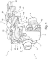
- FIG. 1 shows a designed as a disc valve device valve device 1, which has a disc valve 2 and a drive unit 3, in a perspective view.
- the disk valve 2 has a housing 4, which is formed by a distributor housing 5 and a cover 6.
- the distributor housing 5 has three connections, one of which is designed as an inlet connection 7, and the other two as outlet connections 8 and 9, respectively.
- the distributor housing 5 has a holding device 10 for fastening the valve device 1, for example to a body of a motor vehicle.
- the drive unit 3 is mounted, which is designed in particular as an electromotive actuator and this purpose an electric motor 59, not shown, as well as an operatively connected to the electric motor 59 gear 60 with a drive shaft 70th which can be coupled to a control shaft of the disk valve 2 in order to distribute a medium provided at the inlet connection 7 to the outlet connections 8, 9 as desired. This will be discussed further below.
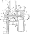
- FIG. 2 shows the disc valve 2 in a longitudinal sectional view.
- the distributor housing 5 is formed substantially cup-shaped, so that it has a U-shaped basic shape seen in longitudinal section.
- the terminals 7, 8, 9 are in this case formed integrally with the distributor housing 5.
- the cover 6 closes the open end of the distributor housing 5, wherein between the cover 6 and the distributor housing 5 in addition a sealing element 11, which is in the present case designed as an O-ring, is provided.
- the inflow port 7 opens - seen axially - above the drain port 8 in the manifold housing 5, ie close to the lid 6.
- From the lid 6 opposite bottom 12 of the manifold housing 5 is a partition 13, which is parallel to the longitudinal extent of the manifold housing 5 and extends axially and ends above the terminal 8 forming an intermediate bottom 14 with its free end face.
- FIG. 3 shows in a cross-sectional view of the disc valve 2 is a plan view of the intermediate bottom 14 or on the manifold housing 5 above the drain ports 8 and 9.
- the partition wall 13 forms two chambers 55, 56, in each of which one of the drain ports 8, 9 opens.
- the chambers 55 and 56 make up about two thirds of the distribution housing 5, while a remaining third of the intermediate bottom 14 is formed.
- the intermediate bottom 14 extends partly web-shaped along the inside of the housing wall over the entire circumference of the Manifold 5, to form a continuous support surface. It is supplemented by the freestanding end face of the partition 13.
- the chambers 55 and 56 thus extend substantially each over approximately 120 ° of the circular distributor housing 5, while a majority of the intermediate bottom 14 is formed by the remaining 120 ° through the partition wall 13.
- a profile seal 15 On the intermediate bottom 14 is a profile seal 15, whose contour corresponds substantially to the contour of the intermediate bottom 14 and is formed elastically deformable.
- the profile seal 15 has an additional opening 16, through which an axial projection 17 of the intermediate bottom 14 for forming an anti-rotation 24 for the profile seal 15 projects therethrough.
- the height of the axial projection 17 is selected such that it projects beyond the profile seal 15 also.
- FIGS. 4A and 4B show a ceramic sealing washer 18 in two perspective views.
- the sealing disc 18 is located on the profile seal 15, wherein the contour of the sealing disc 18 at least substantially corresponds to the contour of the profile seal 15 and the intermediate bottom 14.
- FIG. 4A shows a plan view of the sealing disc 18 from the direction of the lid 6 according to FIG. 2 .
- the sealing disc 18 has two throughflow openings 19, 20, which likewise each represent a circular segment which extends over approximately 120 ° corresponding to the chambers 55 and 56.
- the sealing washer 18 On the cover 16 facing the end face, the sealing washer 18 also has a bearing seat 21, which is formed centrally in the sealing washer 18 as a cylindrical recess.
- the Throughflow openings 19, 20 each provided with a phasing 22, which serve to improve the flow conditions.
- Such Anphasache 22 are also provided on the back of the sealing disc 18 in the region of the flow openings 19, 20, as in FIG. 4B shown.
- the sealing disc 18 on its side facing away from the cover 16 a receiving recess 23, whose contour substantially corresponds to the contour of the axial projection 17 and at least partially receiving the axial projection 17 is used to form a rotation for the sealing disc 18 on the intermediate bottom 14 ,
- the positive rotation prevention 24 a secure arrangement of the hub 18 and the profile seal 15 is ensured in the distributor housing 5 in a simple and cost-effective manner.
- FIG. 5 shows a further plan view of the sealing disc 18, on the lid 6 facing end face.
- a valve disc 25 is also arranged on the sealing disc 18, which is also made of ceramic, and whose outer diameter substantially corresponds to the outer diameter of the sealing disc 18.
- the outer diameter of the valve disc 25 is slightly smaller, in order to avoid frictional contact with the surface of the inside of the distributor housing 5, as well as in FIG. 2 shown.
- the valve disc 25 is formed in a circular segment and extends over a circular segment of about 240 °.
- the remaining 120 ° of the valve disc 25 are free and open-edge formed to form a flow opening 26, which at an overlap position with at least one of the flow openings 19, 20 of the sealing disc 18 sets a flow cross section.
- valve disc 25 Depending on the rotational position of the valve disc 25 is thus a desired flow cross-section between the inlet port 7 and at least one of the drain ports 8, 9 adjustable.
- the valve disc 25 rests flat on the sealing disc 18 and has on its side facing away from the valve disc 18 end two trough-shaped recesses 27 which are arranged on both sides of the center of the valve disc 25 and mirror-symmetrical, but not point-symmetrical, so that a false assembly of the disc valve 2, as explained in more detail later, is avoided.
- the valve disc 25 is provided at the flow opening 26 with Anphasache 29 for improved flow characteristics.
- FIG. 6 shows in a perspective view of a preassembly assembly 30, which consists of the valve disc 25, an intermediate element 31, a spring element 32 and a control shaft 33.
- the control shaft 33 projects with a free end 34 through the opening 28 of the valve disc 25, as in FIG. 2 shown to intervene in the bearing seat 21.
- the free end 34 of the control shaft 33 is also circular-cylindrical, wherein the outer diameter of the free end 34 and the inner diameter of the bearing seat 21 are selected such that together they form a radial sliding bearing for the control shaft 33.
- FIG. 7B shows the control shaft 33 in this case two opposing radially projecting from the control shaft 33 projections 35, 36, wherein the projection 36 on a side wall has an additional projection 37 which in the present Embodiment has a curved contour.
- the intermediate element 31 has an opening 38 corresponding to the contour of the control shaft 33 in the region of the projections 36, 35.
- the opening 38 has laterally on an additional recess 39, in which the additional projection 37 can be inserted.
- the control shaft 33 and the intermediate member 31 can thus be interconnected in only one way. A wrong assembly is thereby reliably prevented.
- FIG. 7A shows a perspective view of the control shaft 33 with the intermediate element 31.
- the intermediate member 31 has on its valve disc 25 side facing two support legs 40 which are preferably integrally formed with the intermediate member 31 and in the recesses 27 of the valve disc 25 can be introduced or intervene. Due to the asymmetrical shape of the recesses 27 and the asymmetrical design of the support legs 40, only a single mounting position for control shaft 33 and valve disc 25 is possible here. As a result, a torsion lock 54 acting positively between control shaft 33 and valve disk 25 is formed as a whole.
- the spring element 32 is formed in the present embodiment as a helical spring 41.
- the coil spring 41 is interposed between the laterally projecting support legs 40 of the intermediate member 31 and a plurality of radially projecting support projections 42 of the control shaft 33 held axially.
- the support projections 42 are distributed uniformly over the circumference of the control shaft 33 and formed integrally therewith. Preferably, two opposing support projections 42 thereby pass over into the lateral projections 35 and 26.
- the support projections 42 together form a first axial stop 43 for the coil spring 41, while the support legs 40 form a second axial stop for the coil spring 41.
- the helical spring 41 is pushed onto the control shaft 33 up to the first axial stop 43, then the intermediate element 31 is pushed onto the control shaft 33 as described above and finally the valve disc 25, so that the feet 40 engage in the recesses 27.
- the intermediate element 31 has a plurality of elastically deformable clamping ribs 45 which extend in a web-like manner parallel to the longitudinal extent of the disk valve 2 or to the axis of rotation of the control shaft 33, as in FIG FIG. 8 shown.
- the dimensioning of the clamping ribs 45 is chosen such that a frictional engagement between the intermediate element 31 and the coil spring 41 and between the intermediate element 31 and valve disc 25 due to the elasticity provided by the biasing force, which ensures the cohesion of the preassembly assembly 30.
- control shaft 33 has a radial projection 46 on the side of the support projections 42 facing away from the spring element 41, as in FIG FIG. 6 shown.
- the radial projection 46 is arranged in a specific, predefined relative position on the control shaft 33 and in particular integrally formed therewith, so that in the assembly of the disc valve 2 and the preassembly assembly 30 is a unique relative position of the valve disc 25 to the radial projection 46 consists. This is ensured by the respective, only one mounting option bidding connections.
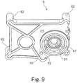
- FIG. 9 shows the cover 6 in a perspective view from below or from the perspective of the distributor housing 5.
- the cover 6 has a bearing opening 47, through which the free end 34 opposite the end of the control shaft 33 can be performed.
- This end is designed as a coupling end 48 and has on its outer periphery an outer toothing 49 which can be coupled to the actuator 3 or brought into operative connection.
- the support projections 42 form on its side opposite the first axial stop 43 side a second axial stop 50, with which the control shaft 33 is supported on the inside of the lid 6.
- a sealing ring 51 is advantageously provided.
- the bearing opening 47 and the coupling end 48 of the control shaft 33 are formed such that the control shaft 33 is mounted radially in the bearing opening 47 and axially on the cover 6.
- the cover 6 on its underside also preferably two rotational stops 52 and 53, which are each formed by an axial projection on the underside of the lid, and which are in the assembled state of the disc valve 2 in the path of movement of the radial projection 46. If the control shaft 33 is actuated by means of the actuator 3, it can be rotated only between the two defined by rotation stops 42 and 43 positions until each of the radial projection 46 against one of Sliding stops 52 or 53 hits.
- the rotary cuffs 52 and 53 may also be formed by a single, correspondingly wide or shaped projection of the cover 6.
- the cover 6 and the distributor housing 5 are formed such that they can be connected to each other only in a certain relative position to each other, so that the lid 6 undergoes a clear alignment on the distributor housing 5.
- the rotation stops 53 and 52 are in known positions with respect to the chambers 55, 56 and with respect to the flow openings 19 and 20.
- the preassembled assembly 30 is first according to FIG. 6 composed. Subsequently, the preassembly assembly is inserted into the distributor housing 5, in which the profile gasket 15 and the gasket 18 are already arranged and aligned according to the axial projection 17, so that the free end 34 of the control shaft 33 engages the bearing seat 21, as in FIG FIG. 2 shown. Subsequently, the lid 6 is pushed with the bearing opening 47 on the coupling end 48 of the control shaft 33 and the control shaft 33 braced due to the first axial stop 43 against the coil spring 41, so that the valve disc 25th is urged spring loaded against the sealing washer 18, so that the valve disc 25 and the sealing washer 18 tightly against each other and an unwanted flow through the disc valve 2 is reliably prevented.
- the lid 6 may, for example, with the distributor housing 5, as, as in FIG. 1 shown, screwed to ensure a permanent connection of the housing 4.
- Valve disc 25 and sealing washer 18 separate or connect, depending on the rotational position of the valve disc 25, the chambers 55 and 56 of the inlet port 7 associated chamber 57, which is bounded by the distributor housing 5, the cover 6 and the valve disc 25 and sealing washer 18.
- the drive unit 3 is mounted on the cover 6 of the disc valve 2.
- the drive unit 3 has a housing 58 in which the electric motor 59 and the transmission 60 are arranged to form a drive device.
- the housing 58 also has a plug connection 61, by means of which the drive unit 3 is electrically contactable.
- the cover 6 of the housing 4 at least three Anschraubdome 62, which protrude in the present embodiment as cylindrical projections perpendicularly from cover 6 parallel to each other.
- a fourth Anschraubdom 62 is provided in the non-visible area.
- the housing 58 has to the Anschraubdomen 62 complementary Anschlußdome 63, which in contrast to the Anschraubdomen 62 have a much shorter axial extent.
- the housing 58 rests on the Anschraubdomen 62, so that the axes of the respective Anschraubdome 62, 63 are aligned.
- the Anschraubdome 62 each have an internal thread into which a screw 64 which is inserted through a through hole of the opposite Anschraubdoms 63, can be screwed to secure the housing 58 to the cover 6 and the housing 4, as in FIG. 1 exemplified for a screw.
- Anschraubdome 63 also differently shaped counter-elements for Anschraubdome 62 may be provided on the housing 58, such as receiving recesses or laterally projecting tabs.
- the housing 58 can be screwed directly onto the screw domes 62 with a housing part.
- the Anschraubdome 62 may be disposed on the housing 58 and the Anschraubdome 63 on the housing 4 or cover 6.
- the size of the Anschraubdome 62 and 63 is according to FIG. 1 chosen such that the housings 58 and 4 are arranged substantially at a distance from each other, so that there is a thermally insulating air gap between them.
- the air gap 66 prevents the drive unit 3 could be heated by the guided through the disc valve 2 and possibly heated medium and thus could be disturbed in its functioning.
- FIG. 10 shows a perspective top view of the cover 6 of the housing 4, the cover 6, the coupling end 48 of the control shaft 38 associated with a splash guard 67.
- the splash guard 67 has a coaxially to the control shaft 33 arranged, the coupling end 48 circumferentially surrounding first Protective wall 68, which is integrally formed with the lid 6.
- the first protective wall 68 has four evenly distributed over its circumference arranged narrow recesses 69.
- the diameter of the protective wall 69 is selected such that it is at a distance from the coupling end 33 of the control shaft 48.
- the height of the protective wall 68 is selected such that it is projected axially from the coupling end 33.
- FIG. 11 shows a sectional view through the valve device 1 according to the section of FIG. 2 , wherein now also the housing 58 of the drive unit 3 is shown, while the disc valve 2 is shown only partially.
- the drive unit has a drive shaft 70, which represents the output shaft of the transmission 60.
- the connection to the transmission 60 and the transmission 60 itself are not shown here for reasons of clarity.
- the drive shaft 70 has at its free, the disc valve 2 facing end or at its coupling end on an axial recess, which has a polygonal shape on its inner surface of the shell, which forms an internal toothing 71.
- the internal toothing 71 is formed complementary to the external toothing 49 of the control shaft 33, so that the internal toothing and the external toothing 49 positively engage with each other and form a positive toothed coupling 76, so that a torque from the drive shaft 70 to the control shaft 33 is preferably transferable without play ,
- the coupling end 48 of the control shaft 33 is mounted axially play in the drive shaft 70.
- the external teeth 49 and the internal teeth 71 together form a coupling device 72, through which the drive shaft 70 and the control shaft 33 are operatively connected to each other for torque transmission.
- the housing 58 of the drive unit 3 has the coupling device 72 associated second protective walls 73 and 74, which are also arranged coaxially to the axis of rotation of the drive shaft 70 and control shaft 33.
- the second protective wall 74 has a diameter which is smaller than the diameter of the first protective wall 68, while the second protective wall 73 has a diameter which is greater than that of the protective wall 68.
- the diameters are chosen such that the first and the second protective walls 68, 73, 74 together form a labyrinth seal 75 which is assigned to the coupling device 72.
- the second protective walls 73, 74 are provided with narrow recesses, which are preferably arranged offset to the recesses 69.
- the recesses 69 and an axial distance between the free end faces of the end walls 68, 73, 74 to the respective opposite housing, cause ventilation and cooling of the coupling device 72.
- the labyrinth seal 75 is also ensured that no splash or other dirt particles in the area the coupling device 72 can pass, so that it is also prevented that moisture in the drive shaft 70 in the drive unit 3 or on the control shaft 33 could get past in the disc valve 2. This ensures that the pumped through the disc valve 2 medium is not contaminated and Moisture can not get into the electrical / electronic components of the drive unit 3.
- the coupling device 72 which is located in the region of the air gap 66, moreover, allows in a simple manner that the disc valve 2 and the drive unit 3 can each be completely pre-assembled before, according to FIG. 1 or 11 be joined together.
- a plug connection between control shaft 33 and drive shaft 70 is made possible in a simple manner, so that only the drive unit 3 has to be plugged onto the disc valve 2 for coupling the shafts with one another.
- This also results in a simple and quick installation of the disc valve device 1.
- the coupling device 72 is disposed between the housings 58 and 4, can also be realized in a simple manner a modular system in which different disc valves 2 with different drive units 3 can be combined are. It does not necessarily have to be disc valves 2 according to the present embodiment, and of course other valve units such as ball valves or the like can be combined with the drive unit 3.
Landscapes
- Engineering & Computer Science (AREA)
- General Engineering & Computer Science (AREA)
- Mechanical Engineering (AREA)
- Physics & Mathematics (AREA)
- Electromagnetism (AREA)
- Fluid Mechanics (AREA)
- General Physics & Mathematics (AREA)
- Lift Valve (AREA)
- Electrically Driven Valve-Operating Means (AREA)
- Valve Housings (AREA)
Claims (7)
- Système de soupape (1), avec une soupape, notamment une soupape de disque (2), comprenant un premier boîtier (4) avec plusieurs connexions (7-9) pour un milieu liquide et/ou gazeux, et avec une unité d'entraînement (3) ayant un second boîtier (58) avec un dispositif d'entraînement (59, 60) y disposé, les boîtiers (4, 58) étant au moins sensiblement espacés l'un de l'autre de telle manière qu'une fente d'air (66) thermiquement isolante est formée entre eux, la soupape (2) ayant un arbre de commande (33) et ladite unité d'entraînement (3) ayant un arbre d'entraînement (70) qui est relié de façon opérationnelle avec le dispositif d'entraînement (59, 60), et qui est relié ou peut être relié de façon opérationnelle avec l'arbre de commande (33) au moyen d'un dispositif d'accouplement (72), le dispositif d'accouplement (72) étant disposé entre le premier et le second boîtier (4, 58), et le dispositif d'accouplement (72) étant associé à une protection anti-éclaboussures (67) qui présente au moins une première paroi de protection (68) entourant au moins sensiblement le dispositif d'accouplement (72) à la périphérie, caractérisé en ce que la protection anti-éclaboussures (67) présente au moins une seconde paroi de protection (73, 74) entourant au moins sensiblement le dispositif d'accouplement (72) à la périphérie, et présentant un diamètre inférieur ou supérieur à la première paroi de protection (68), afin de former, ensemble avec la première paroi de protection (68), un joint d'étanchéité à labyrinthe (75) pour le dispositif d'accouplement (72), l'au moins une première paroi de protection (68) étant formée d'un seul tenant avec le premier boîtier (4), et l'au moins une seconde paroi de protection (73, 74) étant formée d'un seul tenant avec le second boîtier (58), et une distance axiale étant prévue entre les faces frontales libres des parois de protection (68, 73, 74) et le boîtier (4, 58) respectivement opposé, et le premier et/ou le second boîtier (4, 58) présentant au moins un espaceur, notamment formé en tant que bossage pour vis (62, 63).
- Système de soupape selon la revendication 1, caractérisé en ce que le dispositif d'accouplement (72) est réalisé sous forme d'accouplement à engagement positif (76).
- Système de soupape selon l'une quelconque des revendications précédentes, caractérisé en ce que le dispositif d'accouplement (72) est réalisé sous forme d'embrayage à denture (76) ou sous forme de crabot.
- Système de soupape selon l'une quelconque des revendications précédentes, caractérisé en ce que le dispositif d'accouplement (72) est constitué par une denture extérieure (49) de l'arbre de commande (33) et une denture intérieure (71) de l'arbre d'entraînement (70) étant en prise avec la denture extérieure (49).
- Système de soupape selon l'une quelconque des revendications précédentes, caractérisé en ce que la première paroi de protection (68) présente un ou plusieurs évidements (69).
- Système de soupape selon l'une quelconque des revendications précédentes, caractérisé en ce que la seconde paroi de protection (73, 74) présente un ou plusieurs évidements.
- Système de soupape selon les revendications 5 et 6, caractérisé en ce que les évidements (69) de la première paroi de protection (68) et de la seconde paroi de protection (73, 74) sont disposés décalés l'un par rapport à l'autre.
Applications Claiming Priority (2)
| Application Number | Priority Date | Filing Date | Title |
|---|---|---|---|
| DE102012022213.0A DE102012022213B4 (de) | 2012-11-07 | 2012-11-07 | Ventileinrichtung |
| PCT/EP2013/073221 WO2014072376A1 (fr) | 2012-11-07 | 2013-11-07 | Système de soupape |
Publications (2)
| Publication Number | Publication Date |
|---|---|
| EP2917620A1 EP2917620A1 (fr) | 2015-09-16 |
| EP2917620B1 true EP2917620B1 (fr) | 2017-01-04 |
Family
ID=49551603
Family Applications (1)
| Application Number | Title | Priority Date | Filing Date |
|---|---|---|---|
| EP13786672.9A Active EP2917620B1 (fr) | 2012-11-07 | 2013-11-07 | Système de soupape |
Country Status (4)
| Country | Link |
|---|---|
| US (1) | US9410628B2 (fr) |
| EP (1) | EP2917620B1 (fr) |
| DE (2) | DE102012022213B4 (fr) |
| WO (1) | WO2014072376A1 (fr) |
Cited By (2)
| Publication number | Priority date | Publication date | Assignee | Title |
|---|---|---|---|---|
| WO2023237235A1 (fr) | 2022-06-10 | 2023-12-14 | Voss Automotive Gmbh | Vanne multivoies |
| WO2024085463A1 (fr) * | 2022-10-19 | 2024-04-25 | Hanon Systems | Soupape de refroidissement de disque avec disque de commande d'écoulement à mise à niveau automatique |
Families Citing this family (21)
| Publication number | Priority date | Publication date | Assignee | Title |
|---|---|---|---|---|
| EP3470713B1 (fr) * | 2016-06-08 | 2024-05-01 | Zhejiang Sanhua Intelligent Controls Co., Ltd. | Dispositif de régulation de débit et son procédé de fabrication |
| CN107606236B (zh) * | 2016-07-12 | 2020-06-26 | 杭州三花研究院有限公司 | 流量控制装置 |
| EP3486536B1 (fr) * | 2016-07-12 | 2021-08-25 | Zhejiang Sanhua Intelligent Controls Co., Ltd. | Appareil de régulation de débit |
| DE202016004426U1 (de) | 2016-07-20 | 2017-10-23 | Voss Automotive Gmbh | Baugruppeneinheit mit Antriebseinheit und Massenstromregel- oder Ventileinheit und Übertragungseinheit zum Übertragen von Drehmomenten und Rotationen von einer Antriebseinheit an eine Massenstromverstelleinrichtung einer Massenstromregel-oder Ventileinheit |
| DE202016004427U1 (de) | 2016-07-20 | 2017-10-23 | Voss Automotive Gmbh | Massenstromregel- oder Ventileinheit |
| DE102017200573B4 (de) * | 2017-01-16 | 2025-10-30 | Schaeffler Technologies AG & Co. KG | Ventileinheit |
| JP6945859B2 (ja) * | 2018-06-04 | 2021-10-06 | 株式会社不二工機 | 流路切換弁 |
| JP6737380B1 (ja) * | 2019-06-11 | 2020-08-05 | 株式会社デンソー | バルブ装置 |
| CN114391075B (zh) * | 2019-09-13 | 2024-07-19 | 株式会社电装 | 阀装置 |
| DE102019218107A1 (de) * | 2019-11-22 | 2021-05-27 | Mack & Schneider Gmbh | Drehventil |
| US11092249B2 (en) * | 2019-12-12 | 2021-08-17 | Hanon Systems | Binary mode fluid valve |
| JP7674726B2 (ja) * | 2021-02-26 | 2025-05-12 | 株式会社東海理機 | ロータリバルブ |
| JP7517238B2 (ja) * | 2021-04-21 | 2024-07-17 | 株式会社デンソー | バルブ装置 |
| JP7533334B2 (ja) * | 2021-04-21 | 2024-08-14 | 株式会社デンソー | バルブ装置 |
| US11585451B2 (en) | 2021-06-08 | 2023-02-21 | Robert Bosch Llc | Rotary disc valve |
| US11572957B2 (en) | 2021-06-08 | 2023-02-07 | Robert Bosch Gmbh | Rotary disc valve |
| CN113531158B (zh) * | 2021-07-30 | 2023-03-10 | 九通集团有限公司 | 一种三通多晶硅用盘阀 |
| US12013048B2 (en) * | 2021-12-15 | 2024-06-18 | Robert Bosch Llc | Rotary disc valve |
| EP4453454A4 (fr) * | 2021-12-22 | 2026-04-22 | Flowcon Int Aps | Vanne de commande |
| JP7658303B2 (ja) | 2022-03-03 | 2025-04-08 | 株式会社デンソー | バルブ装置 |
| TWM638533U (zh) * | 2022-09-28 | 2023-03-11 | 訊凱國際股份有限公司 | 比例閥 |
Family Cites Families (20)
| Publication number | Priority date | Publication date | Assignee | Title |
|---|---|---|---|---|
| US1842788A (en) * | 1928-11-28 | 1932-01-26 | Kramer Bernhard | Fluid controlling device |
| US3173650A (en) * | 1962-03-05 | 1965-03-16 | Crane Co | Butterfly valve seat construction |
| DE2438875C3 (de) * | 1973-09-24 | 1982-04-01 | Kutzner, Luitpold, Dipl.-Ing., 8000 München | Absperreinrichtung zum Einbau in die Abgasleitung von Feuerstätten |
| DE2530347C3 (de) * | 1975-07-08 | 1979-11-15 | Klein, Schanzlin & Becker Ag, 6710 Frankenthal | Halterung für einen Stellantrieb |
| US4022424A (en) * | 1975-09-29 | 1977-05-10 | General Electric Company | Shaft bearing and seals for butterfly valves |
| US4046350A (en) * | 1976-07-26 | 1977-09-06 | The Parker & Harper Manufacturing Company, Inc. | Power actuated valve |
| FR2463349A1 (fr) * | 1979-08-07 | 1981-02-20 | Gachot Jean | Dispositif de montage pour actionneur de telecommande |
| DE3416970A1 (de) * | 1984-05-08 | 1985-11-14 | Hans 8025 Unterhaching Lechner | Stellventil |
| FR2634853B1 (fr) * | 1988-07-29 | 1990-10-19 | Mecafrance Sa | Perfectionnements aux dispositifs d'etancheite des vannes |
| DE9212236U1 (de) * | 1992-09-10 | 1993-05-27 | Tisch, Walter, 8900 Augsburg | Elektomechanischer Antrieb für Kugelhahnen zum Nachrüsten |
| US5676472A (en) * | 1995-07-10 | 1997-10-14 | Smart Machines | Rotary labyrinth seal |
| US5950576A (en) | 1998-06-30 | 1999-09-14 | Siemens Canada Limited | Proportional coolant valve |
| WO2002059515A1 (fr) * | 2001-01-26 | 2002-08-01 | Yamatake Corporation | Actionneur avec dispositif de clapet |
| DE10323661A1 (de) * | 2003-05-14 | 2004-12-02 | Hirner, Edmund, Dipl.-Ing.(Fh) | Automatischer Flüssigkeitsverteiler |
| JP4285267B2 (ja) * | 2004-02-19 | 2009-06-24 | 株式会社デンソー | 排気ガス再循環装置 |
| WO2005116423A1 (fr) * | 2004-05-31 | 2005-12-08 | Aisan Kogyo Kabushiki Kaisha | Procede de moulage pour corps de papillon et corps de papillon |
| US7556239B2 (en) * | 2007-01-11 | 2009-07-07 | Colonial Engineering, Inc. | Slow close valve |
| SE0700594L (sv) * | 2007-03-05 | 2008-01-15 | Esbe Ab | Ställdon för en flervägsventil och kopplingselement avsett för ett sådant ställdon |
| DE102009024361B4 (de) * | 2009-06-04 | 2021-10-21 | Illinois Tool Works Inc. | Ventilanordnung für eine Verbrennungskraftmaschine |
| GB0910082D0 (en) * | 2009-06-11 | 2009-07-22 | Norgren Ltd C A | Two-part valve |
-
2012
- 2012-11-07 DE DE102012022213.0A patent/DE102012022213B4/de active Active
- 2012-11-07 DE DE202012012980.5U patent/DE202012012980U1/de not_active Expired - Lifetime
-
2013
- 2013-11-07 WO PCT/EP2013/073221 patent/WO2014072376A1/fr not_active Ceased
- 2013-11-07 EP EP13786672.9A patent/EP2917620B1/fr active Active
-
2015
- 2015-05-07 US US14/706,127 patent/US9410628B2/en active Active
Cited By (2)
| Publication number | Priority date | Publication date | Assignee | Title |
|---|---|---|---|---|
| WO2023237235A1 (fr) | 2022-06-10 | 2023-12-14 | Voss Automotive Gmbh | Vanne multivoies |
| WO2024085463A1 (fr) * | 2022-10-19 | 2024-04-25 | Hanon Systems | Soupape de refroidissement de disque avec disque de commande d'écoulement à mise à niveau automatique |
Also Published As
| Publication number | Publication date |
|---|---|
| DE202012012980U1 (de) | 2014-06-18 |
| US20150233476A1 (en) | 2015-08-20 |
| DE102012022213A1 (de) | 2014-05-22 |
| DE102012022213B4 (de) | 2019-04-25 |
| EP2917620A1 (fr) | 2015-09-16 |
| WO2014072376A1 (fr) | 2014-05-15 |
| US9410628B2 (en) | 2016-08-09 |
Similar Documents
| Publication | Publication Date | Title |
|---|---|---|
| EP2917620B1 (fr) | Système de soupape | |
| EP2917619B1 (fr) | Soupape à disque | |
| EP2917621B1 (fr) | Soupape à disque | |
| DE102015207231B4 (de) | Filtereinrichtung | |
| EP2851596B1 (fr) | Élément de traversée murale pour une conduite de fluide et traversée murale | |
| EP2089619A1 (fr) | Dispositif de régulation pour un moteur à combustion interne | |
| DE102007019064B3 (de) | Drehschieber | |
| DE102013209053B4 (de) | Nockenwellenversteller mit einer Federaufnahme und einer Rückstellfeder | |
| WO2012022522A1 (fr) | Soupape d'une pompe à piston présentant un corps de fermeture | |
| DE102013114625A1 (de) | Nockenwellenverstellvorrichtung, Verbrennungsmotor sowie Montageverfahren | |
| EP3227540B1 (fr) | Système de volet pour moteur à combustion interne | |
| DE10356908B4 (de) | Nockenwellenverstelleinrichtung für Verbrennungskraftmaschinen von Fahrzeugen, vorzugsweise Kraftfahrzeugen | |
| DE102011088908A1 (de) | Filtereinrichtung | |
| EP4062088B1 (fr) | Soupape rotative | |
| EP3126651B1 (fr) | Dispositif a volet pour moteur a combustion interne | |
| DE102014117675B4 (de) | Klappenvorrichtung für eine Verbrennungskraftmaschine | |
| WO2018166672A1 (fr) | Soupape à tiroir rotatif destinée à être utilisée dans le domaine automobile | |
| DE102017119921A1 (de) | Steuervorrichtung für ein Fluid | |
| DE3434509A1 (de) | Durchflussschalter fuer stroemungsmedien |
Legal Events
| Date | Code | Title | Description |
|---|---|---|---|
| PUAI | Public reference made under article 153(3) epc to a published international application that has entered the european phase |
Free format text: ORIGINAL CODE: 0009012 |
|
| 17P | Request for examination filed |
Effective date: 20150608 |
|
| AK | Designated contracting states |
Kind code of ref document: A1 Designated state(s): AL AT BE BG CH CY CZ DE DK EE ES FI FR GB GR HR HU IE IS IT LI LT LU LV MC MK MT NL NO PL PT RO RS SE SI SK SM TR |
|
| AX | Request for extension of the european patent |
Extension state: BA ME |
|
| DAX | Request for extension of the european patent (deleted) | ||
| GRAP | Despatch of communication of intention to grant a patent |
Free format text: ORIGINAL CODE: EPIDOSNIGR1 |
|
| INTG | Intention to grant announced |
Effective date: 20160705 |
|
| GRAS | Grant fee paid |
Free format text: ORIGINAL CODE: EPIDOSNIGR3 |
|
| GRAA | (expected) grant |
Free format text: ORIGINAL CODE: 0009210 |
|
| AK | Designated contracting states |
Kind code of ref document: B1 Designated state(s): AL AT BE BG CH CY CZ DE DK EE ES FI FR GB GR HR HU IE IS IT LI LT LU LV MC MK MT NL NO PL PT RO RS SE SI SK SM TR |
|
| REG | Reference to a national code |
Ref country code: GB Ref legal event code: FG4D Free format text: NOT ENGLISH |
|
| REG | Reference to a national code |
Ref country code: CH Ref legal event code: EP |
|
| REG | Reference to a national code |
Ref country code: AT Ref legal event code: REF Ref document number: 859579 Country of ref document: AT Kind code of ref document: T Effective date: 20170115 |
|
| REG | Reference to a national code |
Ref country code: IE Ref legal event code: FG4D Free format text: LANGUAGE OF EP DOCUMENT: GERMAN |
|
| REG | Reference to a national code |
Ref country code: DE Ref legal event code: R096 Ref document number: 502013006003 Country of ref document: DE |
|
| REG | Reference to a national code |
Ref country code: LT Ref legal event code: MG4D Ref country code: NL Ref legal event code: MP Effective date: 20170104 |
|
| PG25 | Lapsed in a contracting state [announced via postgrant information from national office to epo] |
Ref country code: NL Free format text: LAPSE BECAUSE OF FAILURE TO SUBMIT A TRANSLATION OF THE DESCRIPTION OR TO PAY THE FEE WITHIN THE PRESCRIBED TIME-LIMIT Effective date: 20170104 |
|
| PG25 | Lapsed in a contracting state [announced via postgrant information from national office to epo] |
Ref country code: LT Free format text: LAPSE BECAUSE OF FAILURE TO SUBMIT A TRANSLATION OF THE DESCRIPTION OR TO PAY THE FEE WITHIN THE PRESCRIBED TIME-LIMIT Effective date: 20170104 Ref country code: HR Free format text: LAPSE BECAUSE OF FAILURE TO SUBMIT A TRANSLATION OF THE DESCRIPTION OR TO PAY THE FEE WITHIN THE PRESCRIBED TIME-LIMIT Effective date: 20170104 Ref country code: FI Free format text: LAPSE BECAUSE OF FAILURE TO SUBMIT A TRANSLATION OF THE DESCRIPTION OR TO PAY THE FEE WITHIN THE PRESCRIBED TIME-LIMIT Effective date: 20170104 Ref country code: GR Free format text: LAPSE BECAUSE OF FAILURE TO SUBMIT A TRANSLATION OF THE DESCRIPTION OR TO PAY THE FEE WITHIN THE PRESCRIBED TIME-LIMIT Effective date: 20170405 Ref country code: IS Free format text: LAPSE BECAUSE OF FAILURE TO SUBMIT A TRANSLATION OF THE DESCRIPTION OR TO PAY THE FEE WITHIN THE PRESCRIBED TIME-LIMIT Effective date: 20170504 Ref country code: NO Free format text: LAPSE BECAUSE OF FAILURE TO SUBMIT A TRANSLATION OF THE DESCRIPTION OR TO PAY THE FEE WITHIN THE PRESCRIBED TIME-LIMIT Effective date: 20170404 |
|
| PG25 | Lapsed in a contracting state [announced via postgrant information from national office to epo] |
Ref country code: BG Free format text: LAPSE BECAUSE OF FAILURE TO SUBMIT A TRANSLATION OF THE DESCRIPTION OR TO PAY THE FEE WITHIN THE PRESCRIBED TIME-LIMIT Effective date: 20170404 Ref country code: PL Free format text: LAPSE BECAUSE OF FAILURE TO SUBMIT A TRANSLATION OF THE DESCRIPTION OR TO PAY THE FEE WITHIN THE PRESCRIBED TIME-LIMIT Effective date: 20170104 Ref country code: RS Free format text: LAPSE BECAUSE OF FAILURE TO SUBMIT A TRANSLATION OF THE DESCRIPTION OR TO PAY THE FEE WITHIN THE PRESCRIBED TIME-LIMIT Effective date: 20170104 Ref country code: ES Free format text: LAPSE BECAUSE OF FAILURE TO SUBMIT A TRANSLATION OF THE DESCRIPTION OR TO PAY THE FEE WITHIN THE PRESCRIBED TIME-LIMIT Effective date: 20170104 Ref country code: LV Free format text: LAPSE BECAUSE OF FAILURE TO SUBMIT A TRANSLATION OF THE DESCRIPTION OR TO PAY THE FEE WITHIN THE PRESCRIBED TIME-LIMIT Effective date: 20170104 Ref country code: PT Free format text: LAPSE BECAUSE OF FAILURE TO SUBMIT A TRANSLATION OF THE DESCRIPTION OR TO PAY THE FEE WITHIN THE PRESCRIBED TIME-LIMIT Effective date: 20170504 Ref country code: SE Free format text: LAPSE BECAUSE OF FAILURE TO SUBMIT A TRANSLATION OF THE DESCRIPTION OR TO PAY THE FEE WITHIN THE PRESCRIBED TIME-LIMIT Effective date: 20170104 |
|
| REG | Reference to a national code |
Ref country code: DE Ref legal event code: R097 Ref document number: 502013006003 Country of ref document: DE |
|
| PG25 | Lapsed in a contracting state [announced via postgrant information from national office to epo] |
Ref country code: IT Free format text: LAPSE BECAUSE OF FAILURE TO SUBMIT A TRANSLATION OF THE DESCRIPTION OR TO PAY THE FEE WITHIN THE PRESCRIBED TIME-LIMIT Effective date: 20170104 Ref country code: SK Free format text: LAPSE BECAUSE OF FAILURE TO SUBMIT A TRANSLATION OF THE DESCRIPTION OR TO PAY THE FEE WITHIN THE PRESCRIBED TIME-LIMIT Effective date: 20170104 Ref country code: CZ Free format text: LAPSE BECAUSE OF FAILURE TO SUBMIT A TRANSLATION OF THE DESCRIPTION OR TO PAY THE FEE WITHIN THE PRESCRIBED TIME-LIMIT Effective date: 20170104 Ref country code: EE Free format text: LAPSE BECAUSE OF FAILURE TO SUBMIT A TRANSLATION OF THE DESCRIPTION OR TO PAY THE FEE WITHIN THE PRESCRIBED TIME-LIMIT Effective date: 20170104 Ref country code: RO Free format text: LAPSE BECAUSE OF FAILURE TO SUBMIT A TRANSLATION OF THE DESCRIPTION OR TO PAY THE FEE WITHIN THE PRESCRIBED TIME-LIMIT Effective date: 20170104 |
|
| PLBE | No opposition filed within time limit |
Free format text: ORIGINAL CODE: 0009261 |
|
| STAA | Information on the status of an ep patent application or granted ep patent |
Free format text: STATUS: NO OPPOSITION FILED WITHIN TIME LIMIT |
|
| REG | Reference to a national code |
Ref country code: FR Ref legal event code: PLFP Year of fee payment: 5 |
|
| PG25 | Lapsed in a contracting state [announced via postgrant information from national office to epo] |
Ref country code: SM Free format text: LAPSE BECAUSE OF FAILURE TO SUBMIT A TRANSLATION OF THE DESCRIPTION OR TO PAY THE FEE WITHIN THE PRESCRIBED TIME-LIMIT Effective date: 20170104 Ref country code: DK Free format text: LAPSE BECAUSE OF FAILURE TO SUBMIT A TRANSLATION OF THE DESCRIPTION OR TO PAY THE FEE WITHIN THE PRESCRIBED TIME-LIMIT Effective date: 20170104 |
|
| 26N | No opposition filed |
Effective date: 20171005 |
|
| PG25 | Lapsed in a contracting state [announced via postgrant information from national office to epo] |
Ref country code: SI Free format text: LAPSE BECAUSE OF FAILURE TO SUBMIT A TRANSLATION OF THE DESCRIPTION OR TO PAY THE FEE WITHIN THE PRESCRIBED TIME-LIMIT Effective date: 20170104 |
|
| PG25 | Lapsed in a contracting state [announced via postgrant information from national office to epo] |
Ref country code: MC Free format text: LAPSE BECAUSE OF FAILURE TO SUBMIT A TRANSLATION OF THE DESCRIPTION OR TO PAY THE FEE WITHIN THE PRESCRIBED TIME-LIMIT Effective date: 20170104 |
|
| PG25 | Lapsed in a contracting state [announced via postgrant information from national office to epo] |
Ref country code: CH Free format text: LAPSE BECAUSE OF NON-PAYMENT OF DUE FEES Effective date: 20171130 Ref country code: LI Free format text: LAPSE BECAUSE OF NON-PAYMENT OF DUE FEES Effective date: 20171130 |
|
| PG25 | Lapsed in a contracting state [announced via postgrant information from national office to epo] |
Ref country code: LU Free format text: LAPSE BECAUSE OF NON-PAYMENT OF DUE FEES Effective date: 20171107 |
|
| REG | Reference to a national code |
Ref country code: BE Ref legal event code: MM Effective date: 20171130 |
|
| REG | Reference to a national code |
Ref country code: IE Ref legal event code: MM4A |
|
| PG25 | Lapsed in a contracting state [announced via postgrant information from national office to epo] |
Ref country code: MT Free format text: LAPSE BECAUSE OF FAILURE TO SUBMIT A TRANSLATION OF THE DESCRIPTION OR TO PAY THE FEE WITHIN THE PRESCRIBED TIME-LIMIT Effective date: 20170104 |
|
| PG25 | Lapsed in a contracting state [announced via postgrant information from national office to epo] |
Ref country code: IE Free format text: LAPSE BECAUSE OF NON-PAYMENT OF DUE FEES Effective date: 20171107 |
|
| PG25 | Lapsed in a contracting state [announced via postgrant information from national office to epo] |
Ref country code: BE Free format text: LAPSE BECAUSE OF NON-PAYMENT OF DUE FEES Effective date: 20171130 |
|
| PG25 | Lapsed in a contracting state [announced via postgrant information from national office to epo] |
Ref country code: HU Free format text: LAPSE BECAUSE OF FAILURE TO SUBMIT A TRANSLATION OF THE DESCRIPTION OR TO PAY THE FEE WITHIN THE PRESCRIBED TIME-LIMIT; INVALID AB INITIO Effective date: 20131107 |
|
| PG25 | Lapsed in a contracting state [announced via postgrant information from national office to epo] |
Ref country code: CY Free format text: LAPSE BECAUSE OF FAILURE TO SUBMIT A TRANSLATION OF THE DESCRIPTION OR TO PAY THE FEE WITHIN THE PRESCRIBED TIME-LIMIT Effective date: 20170104 |
|
| PG25 | Lapsed in a contracting state [announced via postgrant information from national office to epo] |
Ref country code: MK Free format text: LAPSE BECAUSE OF FAILURE TO SUBMIT A TRANSLATION OF THE DESCRIPTION OR TO PAY THE FEE WITHIN THE PRESCRIBED TIME-LIMIT Effective date: 20170104 |
|
| REG | Reference to a national code |
Ref country code: AT Ref legal event code: MM01 Ref document number: 859579 Country of ref document: AT Kind code of ref document: T Effective date: 20181107 |
|
| PG25 | Lapsed in a contracting state [announced via postgrant information from national office to epo] |
Ref country code: AT Free format text: LAPSE BECAUSE OF NON-PAYMENT OF DUE FEES Effective date: 20181107 |
|
| PG25 | Lapsed in a contracting state [announced via postgrant information from national office to epo] |
Ref country code: TR Free format text: LAPSE BECAUSE OF FAILURE TO SUBMIT A TRANSLATION OF THE DESCRIPTION OR TO PAY THE FEE WITHIN THE PRESCRIBED TIME-LIMIT Effective date: 20170104 |
|
| PG25 | Lapsed in a contracting state [announced via postgrant information from national office to epo] |
Ref country code: AL Free format text: LAPSE BECAUSE OF FAILURE TO SUBMIT A TRANSLATION OF THE DESCRIPTION OR TO PAY THE FEE WITHIN THE PRESCRIBED TIME-LIMIT Effective date: 20170104 |
|
| PGFP | Annual fee paid to national office [announced via postgrant information from national office to epo] |
Ref country code: GB Payment date: 20221122 Year of fee payment: 10 |
|
| GBPC | Gb: european patent ceased through non-payment of renewal fee |
Effective date: 20231107 |
|
| PG25 | Lapsed in a contracting state [announced via postgrant information from national office to epo] |
Ref country code: GB Free format text: LAPSE BECAUSE OF NON-PAYMENT OF DUE FEES Effective date: 20231107 |
|
| PG25 | Lapsed in a contracting state [announced via postgrant information from national office to epo] |
Ref country code: GB Free format text: LAPSE BECAUSE OF NON-PAYMENT OF DUE FEES Effective date: 20231107 |
|
| PGFP | Annual fee paid to national office [announced via postgrant information from national office to epo] |
Ref country code: DE Payment date: 20251127 Year of fee payment: 13 |
|
| PGFP | Annual fee paid to national office [announced via postgrant information from national office to epo] |
Ref country code: FR Payment date: 20251125 Year of fee payment: 13 |