EP2917741B1 - Analysevorrichtung für in-vitro-diagnostik - Google Patents
Analysevorrichtung für in-vitro-diagnostik Download PDFInfo
- Publication number
- EP2917741B1 EP2917741B1 EP13801630.8A EP13801630A EP2917741B1 EP 2917741 B1 EP2917741 B1 EP 2917741B1 EP 13801630 A EP13801630 A EP 13801630A EP 2917741 B1 EP2917741 B1 EP 2917741B1
- Authority
- EP
- European Patent Office
- Prior art keywords
- rack
- preparation
- rotor
- loading
- module
- Prior art date
- Legal status (The legal status is an assumption and is not a legal conclusion. Google has not performed a legal analysis and makes no representation as to the accuracy of the status listed.)
- Active
Links
Images


Classifications
-
- G—PHYSICS
- G01—MEASURING; TESTING
- G01N—INVESTIGATING OR ANALYSING MATERIALS BY DETERMINING THEIR CHEMICAL OR PHYSICAL PROPERTIES
- G01N35/00—Automatic analysis not limited to methods or materials provided for in any single one of groups G01N1/00 - G01N33/00; Handling materials therefor
- G01N35/02—Automatic analysis not limited to methods or materials provided for in any single one of groups G01N1/00 - G01N33/00; Handling materials therefor using a plurality of sample containers moved by a conveyor system past one or more treatment or analysis stations
- G01N35/04—Details of the conveyor system
-
- G—PHYSICS
- G01—MEASURING; TESTING
- G01N—INVESTIGATING OR ANALYSING MATERIALS BY DETERMINING THEIR CHEMICAL OR PHYSICAL PROPERTIES
- G01N35/00—Automatic analysis not limited to methods or materials provided for in any single one of groups G01N1/00 - G01N33/00; Handling materials therefor
- G01N35/02—Automatic analysis not limited to methods or materials provided for in any single one of groups G01N1/00 - G01N33/00; Handling materials therefor using a plurality of sample containers moved by a conveyor system past one or more treatment or analysis stations
- G01N35/026—Automatic analysis not limited to methods or materials provided for in any single one of groups G01N1/00 - G01N33/00; Handling materials therefor using a plurality of sample containers moved by a conveyor system past one or more treatment or analysis stations having blocks or racks of reaction cells or cuvettes
-
- G—PHYSICS
- G01—MEASURING; TESTING
- G01N—INVESTIGATING OR ANALYSING MATERIALS BY DETERMINING THEIR CHEMICAL OR PHYSICAL PROPERTIES
- G01N35/00—Automatic analysis not limited to methods or materials provided for in any single one of groups G01N1/00 - G01N33/00; Handling materials therefor
- G01N2035/00465—Separating and mixing arrangements
- G01N2035/00524—Mixing by agitating sample carrier
-
- G—PHYSICS
- G01—MEASURING; TESTING
- G01N—INVESTIGATING OR ANALYSING MATERIALS BY DETERMINING THEIR CHEMICAL OR PHYSICAL PROPERTIES
- G01N35/00—Automatic analysis not limited to methods or materials provided for in any single one of groups G01N1/00 - G01N33/00; Handling materials therefor
- G01N35/02—Automatic analysis not limited to methods or materials provided for in any single one of groups G01N1/00 - G01N33/00; Handling materials therefor using a plurality of sample containers moved by a conveyor system past one or more treatment or analysis stations
- G01N35/04—Details of the conveyor system
- G01N2035/0401—Sample carriers, cuvettes or reaction vessels
- G01N2035/0403—Sample carriers with closing or sealing means
-
- G—PHYSICS
- G01—MEASURING; TESTING
- G01N—INVESTIGATING OR ANALYSING MATERIALS BY DETERMINING THEIR CHEMICAL OR PHYSICAL PROPERTIES
- G01N35/00—Automatic analysis not limited to methods or materials provided for in any single one of groups G01N1/00 - G01N33/00; Handling materials therefor
- G01N35/02—Automatic analysis not limited to methods or materials provided for in any single one of groups G01N1/00 - G01N33/00; Handling materials therefor using a plurality of sample containers moved by a conveyor system past one or more treatment or analysis stations
- G01N35/04—Details of the conveyor system
- G01N2035/0401—Sample carriers, cuvettes or reaction vessels
- G01N2035/0412—Block or rack elements with a single row of samples
- G01N2035/0415—Block or rack elements with a single row of samples moving in two dimensions in a horizontal plane
-
- G—PHYSICS
- G01—MEASURING; TESTING
- G01N—INVESTIGATING OR ANALYSING MATERIALS BY DETERMINING THEIR CHEMICAL OR PHYSICAL PROPERTIES
- G01N35/00—Automatic analysis not limited to methods or materials provided for in any single one of groups G01N1/00 - G01N33/00; Handling materials therefor
- G01N35/02—Automatic analysis not limited to methods or materials provided for in any single one of groups G01N1/00 - G01N33/00; Handling materials therefor using a plurality of sample containers moved by a conveyor system past one or more treatment or analysis stations
- G01N35/04—Details of the conveyor system
- G01N2035/0439—Rotary sample carriers, i.e. carousels
- G01N2035/0444—Rotary sample carriers, i.e. carousels for cuvettes or reaction vessels
-
- G—PHYSICS
- G01—MEASURING; TESTING
- G01N—INVESTIGATING OR ANALYSING MATERIALS BY DETERMINING THEIR CHEMICAL OR PHYSICAL PROPERTIES
- G01N35/00—Automatic analysis not limited to methods or materials provided for in any single one of groups G01N1/00 - G01N33/00; Handling materials therefor
- G01N35/02—Automatic analysis not limited to methods or materials provided for in any single one of groups G01N1/00 - G01N33/00; Handling materials therefor using a plurality of sample containers moved by a conveyor system past one or more treatment or analysis stations
- G01N35/04—Details of the conveyor system
- G01N2035/046—General conveyor features
- G01N2035/0465—Loading or unloading the conveyor
Definitions
- the present invention relates to an analysis device for in vitro diagnostics, and more particularly to a whole blood analysis device.
- the loading module comprises a storage element provided to allow a stack of racks oriented substantially horizontally, and extraction means arranged to extract the racks out of the storage element in the direction of the stirring module.
- the extraction means are more particularly arranged to move each rack in translation in a horizontal direction and parallel to the plane of said rack.
- the stirring module comprises displacement and tilting means arranged so as to move a rack from a position of introduction into the stirring module in which said rack extends substantially horizontally to a position of withdrawal of said module agitation wherein said rack extends substantially vertically.
- the analysis device described in the document FR 2 907 905 has a complex structure and high manufacturing costs.
- the present invention aims to remedy these drawbacks.
- the technical problem underlying the invention therefore consists in providing an analysis device for in vitro diagnostics which is of simple and economical structure, while ensuring a high analysis rate.
- the present invention relates to an analysis device for in vitro diagnostics, according to claim 1.
- Such a configuration of the stirring module and of the loading and unloading modules makes it possible to ensure a movement of the racks between the loading and unloading positions using simple movement means, which improves reliability and reduces costs. manufacturing costs of the analysis device according to the invention.
- such a configuration of the loading and unloading modules makes it possible to ensure automatic loading and unloading of the racks in and out of the analysis device according to the invention, for example by arranging the loading and unloading conveyors in look at the loading and unloading modules respectively. These arrangements make it possible to ensure high analysis rates.
- the analysis device can be used to perform in particular hematology analyzes, Blood Formula Count (BFS) analyzes, cytology analyzes, flow cytometry analyzes, analyzes. hematology, coagulation haemostasis analyzes, or to prepare slides for automatic microscopic observation of cells and to determine the rate of sedimentation, etc.
- BFS Blood Formula Count
- the stirring module is arranged such that the at least one rack extends substantially in the same plane in the first and second intermediate positions.
- the stirring module is arranged such that the at least one rack extends substantially vertically in the first and second intermediate positions.
- the first and second intermediate positions correspond respectively to positions of insertion and withdrawal of a rack in and out of the stirring module.
- the first and second intermediate positions are respectively arranged at one of the ends of the loading and unloading modules.
- the loading and unloading modules are arranged such that the first and second directions of movement are substantially perpendicular to the plane of the at least one rack.
- the loading and unloading modules are arranged to hold the at least one substantially vertical rack, and more particularly the containers received in said rack, during its movements in the first and second directions of movement.
- the stirring module is arranged to maintain the at least one substantially vertical rack, and more particularly the receptacles received in said rack, during its movements between the first and second intermediate positions.
- the first and second directions of movement are substantially parallel.
- the loading and unloading modules comprise for example respectively a first and a second conveyor.
- the first and second conveyors are advantageously belt or belt conveyors.
- the guidance direction is substantially perpendicular to the first and second directions of movement.
- the guidance direction and the first and second directions of movement are substantially horizontal under conditions of use.
- the guide means are arranged at the ends of the loading and unloading modules.
- the guide means are arranged to guide laterally in translation the at least one rack between the first and second intermediate positions in the direction of guidance.
- the stirring module and the loading and unloading modules define a generally U-shaped rack transport path.
- the rack transport path is substantially horizontal under conditions of 'use.
- the pivot axis of the guide means is substantially parallel to the guide direction.
- the pivot axis of the guide means is substantially horizontal under conditions of use.
- the guide means comprise a rack support delimiting a housing in which the at least one rack is able to slide in the guiding direction, the support of rack being mounted to pivot about the pivot axis.
- the housing delimited by the rack support is designed to simultaneously accommodate a plurality of racks.
- the rack support comprises a rack introduction portion and a rack removal portion, the translational drive means being arranged to translate the at least one received rack. in the housing of the rack holder between the rack introduction portion and the rack removal portion.
- the rack support extends substantially perpendicularly to the loading and unloading modules.
- the rack support is mounted to pivot about the pivot axis between at least a first angular position in which a rack is adapted to be inserted into or withdrawn from the rack support and a second angular position angularly offset from the first angular position, the pivot axis of the rack support being disposed below the housing of the rack support when the rack support is in its first angular position.
- the rack support extends substantially vertically in its first angular position.
- the rack support comprises a guide surface arranged to cooperate with the base of a rack during the sliding of said rack in the housing of the rack support, the pivot axis of the support rack being disposed below the guide surface when the rack support is in its first angular position.
- the rack support comprises at least a first guide wall arranged to cooperate with a side wall of a rack during the sliding of said rack in the housing of the rack support, and a wall of retainer arranged to cooperate with closure elements of receptacles received in said rack so as to retain the receptacles in said rack during the pivoting of the rack support.
- the rack support further comprises a second guide wall arranged to cooperate with a lower surface of a rack during the sliding of said rack in the housing of the rack support.
- the retaining wall is also arranged to cooperate with the closure elements of the receptacles received in said rack during the sliding of said rack in the housing of the rack support.
- the retaining wall comprises a passage orifice intended for the passage of a sampling needle.
- the pivoting means are arranged to pivot the guide means around the pivot axis according to an angular displacement of between 0 and 160 °, and for example between 0 and approximately 120 °. °.
- the rack support is inclined at an angle of approximately 120 ° relative to the vertical when it is in its second angular position.
- the sampling module is placed near the agitation module.
- the translational drive means are arranged to immobilize the at least one rack in at least one sampling position arranged between the first and second intermediate positions, the sampling module being arranged to taking a sample of biological fluid in at least one container received in said rack when said rack is immobilized in the at least one sampling position.
- the translational drive means are arranged to immobilize the at least one rack in a plurality of sampling positions arranged between the first and second intermediate positions, each sampling position corresponding to a position of said rack in which the module sampling device is arranged to take a sample of biological fluid in one of the containers received in said rack.
- the translational drive means are arranged to immobilize said rack in N distinct sampling positions.
- the translational drive means comprise at least one fork intended to cooperate with a rack received in the housing of the rack support, a guide rail extending parallel to the guidance direction. and on which the fork is slidably mounted, an endless belt, such as a toothed endless belt, connected to the fork, and a drive motor arranged to drive the endless belt.
- the stirring module is arranged to immobilize the guide means in a transfer position in which the at least one rack is able to be guided in translation between the first and second intermediate positions.
- the pivoting means comprise a drive motor, such as a stepping motor, coupled, for example by means of an endless belt, such as a belt. endless notched, to a pulley integral in rotation with the rack support and axis coincident with the pivot axis of the rack support.
- a drive motor such as a stepping motor
- an endless belt such as a belt. endless notched
- the analysis device comprises detection means arranged to detect the insertion of a rack in the housing of the rack support, and control means connected to the detection means and arranged to initiate pivoting of the rack support when the detecting means has detected the insertion of a rack into the housing of the rack support.
- the pivoting means are arranged to pivotally drive the guide means according to a rocking movement about the pivot axis.
- the pivoting means are for example arranged to generate at least twelve rockings per minute of the guide means around the pivot axis, preferably with pauses between the rockings so that the air bubble present in each receptacle received in the rack can travel the entire height of the container, and thus cause optimal mixing of the sample.
- the pivoting means are arranged to allow tilting of the rack between a position in which the rack is oriented upward and a position in which the rack is oriented downward, and more particularly between a position in which the containers received in the rack are oriented towards the up and a position in which the containers received in the rack face down.
- the loading rotor is removable.
- each housing provided on the loading rotor opens into the upper face of the loading rotor.
- At least two housings provided on the loading rotor have different dimensions. These arrangements allow the mounting of containers of different dimensions on the loading rotor.
- Each preparation bowl may for example extend in a plane substantially perpendicular to a diameter of the preparation rotor.
- the medium of each preparation cuvette passes through a diameter of the preparation rotor.
- the preparation cuvettes are distributed over the periphery of the preparation rotor, and preferably regularly distributed over the periphery of the preparation rotor.
- At least one preparation bowl has a rounded bottom, the concavity of which faces upwards.
- the preparation rotor is transparent.
- the preparation rotor is made of transparent plastic, such as polymethyl methacrylate (PMMA).
- PMMA polymethyl methacrylate
- the rotary drive means associated with the preparation rotor are advantageously arranged to drive the preparation rotor in rotation in a first direction and in a second direction opposite to the first direction.
- the rotary drive means associated with the preparation rotor are for example arranged to drive the preparation rotor alternately in rotation in the first and second directions, for example at an oscillation frequency corresponding to the natural oscillation frequency of the liquid. contained in the preparation cuvette (s).
- the means for driving in rotation associated with the preparation rotor comprise a stepping motor.
- the preparation and measurement module comprises regulating means arranged to regulate the temperature of the preparation cuvettes to a determined level.
- the preparation and measurement module comprises at least one measurement and / or analysis station arranged around the preparation rotor.
- the at least one measurement and / or analysis station is, for example, a spectrophotometric reading module, a fluorescence reading module, a luminescence reading module, a coagulation measurement module.
- the preparation rotor comprises a rotating body on which the preparation cuvettes are removably mounted.
- the analysis device comprises a supply station arranged to supply the rotary body with preparation cuvettes.
- the preparation rotor comprises a rotating body on which the preparation cuvettes are formed.
- the at least one rack comprises windows allowing optical reading of identification codes carried by the receptacles received on said rack.
- the sampling module comprises a sampling head equipped with a sampling needle, first displacement means arranged to move the sampling head in translation in a direction which is substantially horizontal and perpendicular to the guiding direction, and second displacement means arranged to move the sampling head in a substantially vertical direction.
- the sampling needle has a tip capable of piercing the closure elements of the receptacles received in the at least one rack.
- the sampling module comprises at least one rinsing well capable of receiving and rinsing the sampling needle from the sampling head.
- the loading and unloading modules comprise first and second guide means arranged to cooperate with complementary guide means provided on the at least one rack.
- the first and second guide means comprise for example respectively a first and a second guide rails able to cooperate with the complementary guide means provided on the at least one rack, and more particularly on the base of said rack.
- the loading and unloading modules each have a storage capacity of at least fifteen racks.
- each rack comprises a plurality of housings substantially aligned in the plane of said rack and intended to receive one of the corresponding containers.
- each housing comprises an introduction opening opening out to the outside of the rack and shaped to allow the introduction of the corresponding container into said housing.
- Each container is preferably removably mounted in the corresponding rack.
- each housing has a substantially circular section.
- each container is mounted to rotate freely in the corresponding housing.
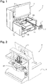
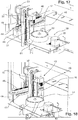
- the figure 1 represents an analysis device 2 for in vitro diagnosis, and more particularly for carrying out blood tests, such as whole blood tests.
- the analysis device 2 comprises a frame 3, a communication and display interface 4 mounted on the frame 3, and on-board electronics (not shown in the figures) housed in the frame 3.
- the communication and display interface 4 comprises for example a touch screen 5 connected to a PC type computer.
- the PC type computer is more particularly designed to record analysis requests loaded manually by an operator using a touch screen 5 or originating from a central unit of an analysis laboratory, to send requests for analysis. analysis with on-board electronics, to recover measured data, process them using specific algorithms, and make the results available to the operator.
- the analysis device 2 comprises a plurality of racks 6, also called racks or cassettes, each intended to receive a plurality of containers 7 equipped with sealing elements 8 and containing samples of biological liquid to be analyzed, such as blood samples.
- the containers 7 are sample tubes.
- Each rack 6 has a general parallelepipedal shape and comprises a plurality of housings 9, preferably cylindrical, aligned in the extension plane of said rack 6.
- the housings 9 are open upwards in order to allow easy introduction and removal of the containers. 7 in and out of the housings 9.
- each housing 9 is shaped so that the corresponding container 7 is mounted to rotate freely in said housing 9.
- Each rack 6 also comprises a first series of windows 11 allowing optical reading of identification codes carried by the receptacles 7, and a second series of windows 12 enabling visualization of the contents of said receptacles 7.
- each rack 6 further comprises a transverse notch 13, the function of which will be explained below.
- each rack 6 is designed to receive five containers 7. However, each rack 6 could be designed to receive less or more than five containers 7.
- the analysis device 2 further comprises a loading module 14 arranged to move each rack 6 loaded in the loading module 14 between a loading position P1 (see figure 5 ) and a first intermediate position P2 (see figure 10 ) in a first direction of movement D1 horizontal and perpendicular to the extension plane of said rack 6.
- the loading module 14 comprises a guide rail 15 extending parallel to the first direction of movement D1 and arranged to cooperate with the transverse notch 13 of each rack 6 loaded in the loading module 14 so as to guide said translation in translation. rack during its movements between the loading position P1 and the first intermediate position P2.
- the guide rail 15 has a dovetail section and the transverse notch 13 of each rack 6 has a complementary shape.
- the loading module 14 further comprises a conveyor 16 comprising two conveyor belts 17 each equipped with a plurality of drive fingers 18 (shown on the figure. figure 9 ) arranged to cooperate with the base of each rack 6 loaded in the loading module 14 so as to drive said rack in translation between the loading position P1 and the first intermediate position P2.
- the two conveyor belts 17 are driven by a motor 19 mounted on the frame 3 and more particularly shown in the figure. figure 11 .
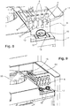
- the analysis device 2 also comprises a stirring module 21 comprising a rack support 22 arranged to guide in translation at least one rack between the first intermediate position P2 and a second intermediate position P3 in a horizontal and perpendicular guiding direction D2. to the first direction of travel D1.
- the rack support 22 delimits a housing 23 into which is able to be inserted, preferably completely, at least one rack 6, and for example up to three racks 6 simultaneously.
- the rack support 22 comprises at least a first guide wall 24 arranged to cooperate with a side wall of a rack 6 introduced into the housing 23, a second guide wall 25 arranged to cooperate with the closure elements 8 of the containers. 7 received in the rack, and a third guide wall 26 arranged to cooperate with a lower surface of the rack 6.
- the second guide wall 25 is more particularly arranged to cooperate with the closure elements 8 of the receptacles 7 received in the rack 6 so as to retain the containers 7 in the rack 6 during the pivoting of the rack support 22, and thus also forms a retaining wall.
- the second guide wall 25 further comprises a passage orifice 25a intended for the passage of a sampling needle.
- the rack support 22 is mounted to pivot with respect to the frame 3 about a horizontal pivot axis A and parallel to the guiding direction D2.
- the stirring module 21 also comprises pivoting means arranged to pivotally drive the rack support 22 about the pivot axis A between a first angular position in which the rack support 22 extends vertically (see figure 5 ) and a second angular position (see figure 6 ) wherein the rack support 22 is inclined relative to the vertical.
- the pivoting means are more particularly arranged to pivot the rack support 22 around the pivot axis A according to an angular displacement of between 0 and 160 °, and for example between 0 and approximately 120 °.
- the pivoting means are arranged to allow a tilting of a rack 6 loaded in the stirring module 21 between a position in which the containers 7 received in the rack 6 are oriented upward and a position in which the containers 7 received in the rack 6 are oriented downward.
- the pivoting means are arranged to pivot the rack support 22 according to a rocking movement around the pivot axis A.
- the pivot means are for example arranged to generate at least twelve rockings per minute of the rack support 22 around the pivot axis A, preferably with pauses between the swings so that the air bubble present in each container 7 received in a rack 6 loaded in the stirring module 21 can travel the entire height of the container 7, and thus cause optimal mixing of the sample contained in the container.
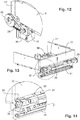
- the pivoting means comprise a stepping motor 27 (see figure 12 ) whose output shaft is coupled, for example by means of an endless belt 28, such as a toothed endless belt, to a pulley 29 integral in rotation with the carrier support 22 and of coincident axis with the pivot axis A.
- an endless belt 28 such as a toothed endless belt
- the stirring module 21 further comprises translational drive means arranged to drive in translation a rack 6 loaded in the stirring module 21 between the first and second intermediate positions P2, P3 in the guiding direction D2.
- the translational drive means comprise (see figures 13 and 14 ) in particular a guide rail 31 mounted on the frame 3 and extending parallel to the guide direction D2, and a fork 32 slidably mounted on the guide rail 31 and intended to cooperate with a rack 6 received in the housing 23 of the rack support 22.
- the fork 32 comprises in particular two parallel branches 33 spaced with respect to each other by a distance corresponding substantially to the length of a rack 6, and intended to extend through a lumen of passage 34 provided on the rack support 22.
- the translational drive means also comprise an endless belt 35, such as a toothed endless belt, connected to the fork 32, and a drive motor 36 (see figure 12 ) whose output shaft is provided with a pinion, preferably toothed, designed to drive the endless belt 35.
- an endless belt 35 such as a toothed endless belt
- a drive motor 36 see figure 12
- pinion preferably toothed
- the fork is provided with optical detection means arranged to detect the insertion of a rack 6 in the housing 23 of the rack support 22, and the analysis device 2 is provided with control means connected to the detection means and arranged to initiate the pivoting of the rack support 22 when the detection means have detected the insertion of a rack 6 in the housing 23.
- the rack support 22 and the translational drive means are preferably arranged to keep each rack 6 substantially vertical during its movements in the guiding direction D2.
- the analysis device 2 further comprises an unloading module 37 arranged to move a rack 6 between the second intermediate position P3 and an unloading position P4 in a second direction of movement D3 horizontal and perpendicular to the extension plane of said rack 6
- the second direction of movement D3 is advantageously parallel to the first direction of movement D1 and perpendicular to the guide direction D2.
- the unloading module 37 is substantially identical to the loading module 14.
- the unloading module 37 also comprises a guide rail 38 extending parallel to the second direction of movement D2 and arranged to cooperate with the transverse notch 13 of each rack 6 loaded in the unloading module 37 so as to guide said rack in translation during its movements between the second intermediate position P3 and the unloading position P4.
- the unloading module 37 further comprises a conveyor 39 comprising two conveyor belts 41 each equipped with a plurality of drive fingers.
- the two conveyor belts 41 are driven by a motor 42 mounted on the frame 3 and more particularly shown in the figure. figure 11 .
- the stirring 21, loading 14 and unloading 37 modules define a substantially horizontal carrier transport path in the general shape of a U.
- Such a configuration of the loading and unloading modules 14, 37 ensures loading and unloading. automatic unloading of the racks 6 in and out of the analysis device 2, for example by arranging loading conveyors and unloading respectively facing the loading and unloading modules 14, 37.
- the translational drive means are also arranged to vertically immobilize each rack received in the stirring module 21 in a plurality of sampling positions arranged between the first and second intermediate positions P2, P3, and more particularly in as many positions collection only receptacles 7 received in said rack 6.
- the analysis device 2 further comprises a sampling module 43 disposed near the agitation module 21 (see the figures 16 to 18 ).
- the sampling module 43 is arranged to take samples of biological fluid in the containers 7 received in each rack 6 loaded in the stirring module 21.
- the sampling module 43 is arranged to take a sample of biological fluid in one of the containers received in said rack 6.
- the sampling module 43 comprises in particular a sampling support 44, and a sampling head 45 mounted on the sampling support 44 and equipped with a sampling needle 46, the sampling needle 46 having a tip capable of piercing the elements. sealing 8 of the containers 7 received in each rack 6.
- the sampling module 43 further comprises first displacement means arranged to move the sampling head 44 in translation in a horizontal direction and perpendicular to the guiding direction D2, and second displacement means arranged to move the sampling head 44 in a vertical direction.
- the sampling module 43 further comprises a rinsing well 54 capable of receiving and rinsing the sampling needle 46 from the sampling head 45.
- the sampling module 43 could also include level detection means.
- level detection means make it possible, on the one hand, to avoid systematically plunging the sampling needle almost to the bottom of the receptacles, as do most hematology analyzers, which contaminates almost the entire length of the vessel. sampling needle, and on the other hand to be able to pipette reactive products into the vials with precision.
- the level detection means may for example comprise a capacitive detection system.
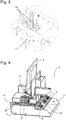
- the analysis device 2 comprises a loading rotor 55 arranged between the loading and unloading modules 14, 37 and having a substantially vertical axis of rotation.
- the loading rotor 55 comprises a plurality of housings 56 capable of receiving receptacles 57 containing samples of biological fluid to be analyzed or reactive products.
- Each housing 56 provided on the loading rotor 55 opens into the upper face of the loading rotor 55 in order to allow easy introduction and removal of the containers 57 in and out of the loading rotor 55.
- the loading rotor comprises housings 56 having different dimensions in order to allow the mounting of containers 57 of different dimensions on the loading rotor 55.
- the analysis device 2 also comprises means for driving in rotation associated with the loading rotor 55 and arranged to rotate the loading rotor 55 about its axis of rotation.
- the rotational drive means associated with the loading rotor 55 comprise for example a drive motor 58, such as a stepping motor, visible on the figure. figure 11 .
- the sampling module 43 is arranged to take, using the sampling head 45, samples or reactive products in the containers 57 received in the loading rotor 55.
- the loading rotor 55 makes it possible to load manually and at any time into the analysis device, receptacles 57 containing samples to be analyzed and which must be shaken manually beforehand, and / or bottles of reagent products.
- the analysis device 2 further comprises a preparation and measurement module 59 arranged inside the frame 3.
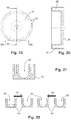
- the preparation and measurement module 59 comprises in particular a preparation rotor 61 with a substantially vertical axis of rotation. As shown more particularly on figures 19 to 22 , the preparation rotor 61 comprises a plurality of preparation bowls 62 regularly distributed over the periphery of the preparation rotor 61.
- the sampling module 43 is arranged to supply the preparation cuvettes 62 with biological liquid samples or with reactive products using the sampling head 45.
- the position of the sampling head 45 during feeding of the preparation cuvettes 62 is aligned with the positions of the sampling head 45 respectively when taking liquid from a container 57 received in the loading rotor 55, when taking samples from a container 7 received in a rack 6, and when rinsing the sampling needle 46.
- Each preparation bowl 62 advantageously extends in a plane perpendicular to a diameter of the preparation rotor 61 and the middle of each preparation bowl 62 passes through the corresponding diameter of the preparation rotor 61.
- the preparation rotor 61 comprises a rotating body on which the preparation cuvettes 62 are formed.
- the preparation rotor 61 could comprise a rotating body on which the preparation cuvettes are removably mounted.
- the analysis device 2 would include a supply station arranged to supply the rotary body with preparation cuvettes.
- each preparation bowl 62 has a rounded bottom whose concavity is turned upwards.
- the preparation and measurement module 59 further comprises rotational drive means associated with the preparation rotor 61. These rotational drive means are advantageously arranged to drive the preparation rotor 61 in rotation around its axis of rotation. alternately in a first direction and in a second direction opposite to the first direction, for example at an oscillation frequency corresponding to the natural oscillation frequency of the liquid contained in the preparation bowls 62.
- the means for driving in rotation associated with the preparation rotor 61 comprise a stepping motor 63 more particularly visible on the figure. figure 17 .
- the preparation and measurement module 59 may advantageously comprise regulation means arranged to regulate the temperature of the preparation cuvettes 62 to a determined level.
- the regulating means may comprise in particular a thermally conductive metallic plate 64 arranged under the preparation rotor 61 and heating means arranged to heat the thermally conductive metallic plate 64.
- the preparation rotor 61 is for example made of transparent plastic, such as polymethyl methacrylate (PMMA). These arrangements make it possible to perform various measurements through the material of the preparation rotor 61, such as photometric measurements.
- PMMA polymethyl methacrylate
- the analysis device advantageously comprises at least one measuring station arranged around the preparation rotor 61, such as a photometric measuring station suitable for measuring in particular the hemoglobin level in the sample to be analyzed, or the level of D-dimer or CRP in the sample to be analyzed.
- a photometric measuring station suitable for measuring in particular the hemoglobin level in the sample to be analyzed, or the level of D-dimer or CRP in the sample to be analyzed.
- the analysis device 2 could furthermore also comprise a spectrophotometric reading module, a fluorescence reading module, a luminescence reading module or even a coagulation measurement module arranged around the preparation rotor 61.
- the analysis device 2 may further include one or more cytometric measuring heads 65 which make it possible to perform all the hematology measurements relating to the blood count with precision.
- the analysis device 2 could for example comprise a first cytometric measuring head 65 for carrying out measurements of red blood cells or platelets, and a second cytometric measuring head 65 for carrying out measurements of white blood cells. These arrangements make it possible to carry out measurements in parallel, and therefore to increase the rate of analysis of the analysis device 2 according to the invention.
- the analysis device 2 also comprises a flat container 66 arranged under the loading and unloading modules 14, 37, and intended to contain isotonic dilution liquid acting as system liquid.
- the flat can 66 is advantageously provided with a rubber stopper pierced automatically at the end of the stroke by a suitable piercing member, which both makes the system liquid available to the analysis device 2, but also allows the open air.
- the system liquid will be heated by known devices.
- the container intended to receive used liquid is not shown in the figures.
- the operation of the analysis device 2 is as follows.
- Racks 6 provided with receptacles 7 containing samples of biological liquid to be analyzed are loaded manually or automatically into the loading module 14. These racks 6 are successively brought to the rack support 22 with a view to their agitation using the agitation module 21.
- each rack 6 is then moved to a first sampling position.
- the sampling head 45 of the sampling module 43 is then moved such that the sampling needle 46 passes through the passage opening 25a provided on the second guide wall 25 and takes a predetermined volume of biological fluid sample at analyze in a first container 7 received in the rack 6 immobilized in the first sampling position.
- the second guide wall 25 which cooperates with the closure element 8 of the first container 7, maintains the first container 7 in the housing 23 of the rack support 22.
- sampling head 45 of the sampling module 43 is then moved such that the sampling needle 46 introduces the predetermined volume of sample into a preparation cuvette 62 of the preparation rotor 61. Then, system liquid withdrawn from it. flat can 66 is introduced, using an appropriate feed station, into said preparation cuvette 62 in order to carry out a first dilution of the biological liquid to be analyzed.
- the preparation rotor is rotated around its axis of rotation alternately in a first direction S1 and in a second direction S2 opposite to the first direction S1, according to an oscillation frequency corresponding substantially to the natural oscillation frequency of the mixture contained in the preparation bowl 62.
- Such reciprocating rotational movements of the preparation rotor 61 generate movements of the liquids contained in the preparation bowl 62 as shown on the figure. figure 22 and ensure optimum mixing of these liquids, due to the arrangement of the preparation cuvettes 62 relative to the axis of rotation of the preparation rotor and the shape of the preparation cuvettes 62. It should be noted that the walls sides of the preparation basins are high enough to avoid liquid overflows during these oscillations.
- the mixture obtained is aspirated by the sampling needle 46 and dispensed into an empty preparation cuvette 62, for example to carry out a second dilution.
- the preparation rotor is driven in rotation in order to position the preparation cuvette 62 containing the mixture to be analyzed in front of a distribution station for the Lyse reagents to obtain the solutions ready for carrying out tests. haematological measurements.
- the various preparation cuvettes 62 are rinsed using an appropriate rinsing station if they are irremovable, or they are replaced by other preparation cuvettes if they are disposable, with a view to the analysis of another receptacle 7 received in the rack 6 in the sampling position.
- the translational drive means move the corresponding rack 6 into a second sampling position, so as to allow the taking of a sample in a second receptacle 7 housed in said rack 6 and perform, using the sampling module 43, and the analysis of this sample. These steps are repeated so as to allow the analysis of the samples contained in the various containers 7 received in the rack 6.
- the rack 6 When the samples contained in the various receptacles 7 housed in the disposed rack 6 have been analyzed, the rack 6 is moved to the second intermediate position P3 with a view to its unloading using the unloading module 37. However, if necessary, the rack 6 can be returned to a sampling position by reversing the direction of operation of the drive motors 36, 42 in order to carry out a new analysis of a sample contained in one of the containers housed in said rack 6.
- the analysis device 2 makes it possible to carry out specific or urgent analyzes using the loading rotor 55 by placing therein receptacles 57 containing samples of biological liquid to be analyzed or specific reactive products.
- the loading rotor 55 is rotated to dispose the desired container 57 in a predetermined position (see figure 16 ) allowing a sampling of the liquid contained in the latter using the sampling needle 46, this liquid then being introduced into a preparation bowl 62 of the preparation rotor 61.
Landscapes
- Chemical & Material Sciences (AREA)
- General Health & Medical Sciences (AREA)
- Life Sciences & Earth Sciences (AREA)
- Health & Medical Sciences (AREA)
- Analytical Chemistry (AREA)
- Biochemistry (AREA)
- Physics & Mathematics (AREA)
- General Physics & Mathematics (AREA)
- Immunology (AREA)
- Pathology (AREA)
- Chemical Kinetics & Catalysis (AREA)
- Automatic Analysis And Handling Materials Therefor (AREA)
- Sampling And Sample Adjustment (AREA)
Claims (10)
- Analysevorrichtung (2) für In-vitro-Diagnostik, umfassend:- mindestens einen Träger (6), der dazu bestimmt ist, eine Vielzahl von Behältern (7) aufzunehmen, die mit Verschlusselementen (8) versehen sind und Proben von Körperflüssigkeiten enthalten, die zu analysieren sind,- ein Lademodul (14), das angeordnet ist, um den mindestens einen Träger (6) zwischen einer Ladeposition (P1) und einer ersten Zwischenposition (P2) gemäß einer ersten Bewegungsrichtung (D1) quer zu der Ebene des mindestens einen Trägers zu bewegen,- ein Schüttelmodul (21), das angeordnet ist, um den mindestens einen Träger (6) zwischen der ersten Zwischenposition (P2) und einer zweiten Zwischenposition (P3) zu bewegen und um den mindestens einen Träger (6) zu schütteln, wobei das Schüttelmodul so angeordnet ist, dass sich der mindestens eine Träger im Wesentlichen gemäß einer gleichen Ausrichtung in der ersten und zweiten Zwischenposition erstreckt, wobei das Schüttelmodul (21) umfasst:- Führungsmittel, die angeordnet sind, um den mindestens einen Träger (6) zwischen der ersten und zweiten Zwischenposition gemäß einer Führungsrichtung (D2) verschiebend zu führen,- Verschiebungsantriebsmittel, die angeordnet sind, um den mindestens einen Träger (6) zwischen der ersten und zweiten Zwischenposition gemäß der Führungsrichtung verschiebend anzutreiben, und- ein Entlademodul (37), das angeordnet ist, um den mindestens einen Träger (6) zwischen der zweiten Zwischenposition (P3) und einer Entladeposition (P4) gemäß einer zweiten Bewegungsrichtung (D3) quer zu der Ebene des mindestens einen Trägers zu bewegen, und- ein Entnahmemodul (43), das angeordnet ist, um Proben einer Körperflüssigkeit in den Behältern (7) zu entnehmen, die in dem mindestens einem Träger (6) aufgenommen sind,dadurch gekennzeichnet, dass das Schüttelmodul (21) des Weiteren Schwenkmittel umfasst, die angeordnet sind, um die Führungsmittel schwenkend um eine Schwenkachse (A) anzutreiben, und dadurch, dass die Analysevorrichtung des Weiteren umfasst:∘ einen Laderotor (55), der zwischen dem Lade- und Entlademodul (14, 37) und mit einer im Wesentlichen vertikalen Drehachse angeordnet ist, und Drehantriebsmittel, die mit dem Laderotor (55) verbunden und angeordnet sind, um den Laderotor um seine Drehachse anzutreiben, wobei der Laderotor (55) eine Vielzahl von Aussparungen (56) umfasst, die geeignet sind, Behälter (57) aufzunehmen, die Proben einer Körperflüssigkeit, die zu analysieren sind, oder Reagenzprodukte enthalten, wobei das Entnahmemodul (43) angeordnet ist, um Proben oder Reagenzprodukte in den Behältern (57) zu entnehmen, die in dem Laderotor (55) aufgenommen sind,
und/oder∘ ein Vorbereitungs- und Messmodul (59), umfassend:- einen Vorbereitungsrotor (61) mit einer im Wesentlichen vertikalen Drehachse, wobei der Vorbereitungsrotor (61) eine Vielzahl von Vorbereitungswannen (62) umfasst, wobei das Entnahmemodul (43) angeordnet ist, um die Vorbereitungswannen (62) mit Proben einer Körperflüssigkeit oder mit Reagenzprodukten, die zuvor entnommen wurden, zu versorgen, und- Drehantriebsmittel, die mit dem Vorbereitungsrotor (61) verbunden und angeordnet sind, um den Vorbereitungsrotor um seine Drehachse in Drehung zu versetzen. - Analysevorrichtung nach Anspruch 1, wobei das Lade- und Entlademodul (14, 37) angeordnet sind, um den mindestens einen Träger (6) bei seinen Bewegungen gemäß der ersten und zweiten Bewegungsrichtung im Wesentlichen vertikal zu halten.
- Analysevorrichtung nach Anspruch 1 oder 2, wobei das Schüttelmodul (21) angeordnet ist, um den mindestens einen Träger (6) bei seinen Bewegungen zwischen der ersten und zweiten Zwischenposition im Wesentlichen vertikal zu halten.
- Analysevorrichtung nach einem der Ansprüche 1 bis 3, wobei das Schüttelmodul (21) und das Lade- und Entlademodul (14, 37) einen Transportweg des Trägers definieren, der im Allgemeinen U-förmig ist.
- Analysevorrichtung nach einem der Ansprüche 1 bis 4, wobei das Lade- und Entlademodul (14, 37) jeweils ein erstes und ein zweites Förderband (16, 39) umfassen.
- Analysevorrichtung nach einem der Ansprüche 1 bis 5, wobei die Führungsmittel einen Trägerhalter (22) umfassen, der eine Aussparung (23) begrenzt, in der der mindestens eine Träger (6) gemäß der Führungsrichtung gleiten kann, wobei der Trägerhalter schwenkend um die Schwenkachse (A) montiert ist.
- Analysevorrichtung nach Anspruch 6, wobei der Trägerhalter (22) mindestens eine erste Führungswand (24) umfasst, die angeordnet ist, um mit einer Seitenwand eines Trägers (6) beim Gleiten des Trägers in der Aussparung (23) des Trägerhalters zusammenzuwirken, und eine Rückhaltewand (25), die angeordnet ist, um mit Verschlusselementen (8) der Behälter (7), die in dem Träger (6) aufgenommen sind, zusammenzuwirken, sodass die Behälter (7) in dem Träger (6) beim Schwenken des Trägerhalters (22) zurückgehalten werden.
- Analysevorrichtung nach einem der Ansprüche 1 bis 7, wobei sich jede Vorbereitungswanne (62) in einer Ebene im Wesentlichen senkrecht zu einem Durchmesser des Vorbereitungsrotors (61) erstreckt.
- Analysevorrichtung nach einem der Ansprüche 1 bis 8, wobei mindestens eine Vorbereitungswanne (62) einen abgerundeten Boden aufweist, dessen Konkavität nach oben gewandt ist.
- Analysevorrichtung nach einem der Ansprüche 1 bis 9, wobei die Drehantriebsmittel, die mit dem Vorbereitungsrotor (61) verbunden sind, angeordnet sind, um den Vorbereitungsrotor in einer ersten Richtung (S1) und in einer zweiten Richtung (S2), die der ersten Richtung entgegengesetzt ist, in Drehung zu versetzen.
Applications Claiming Priority (2)
| Application Number | Priority Date | Filing Date | Title |
|---|---|---|---|
| FR1260661A FR2998057B1 (fr) | 2012-11-09 | 2012-11-09 | Dispositif d’analyse pour diagnostic in vitro |
| PCT/FR2013/052597 WO2014072616A1 (fr) | 2012-11-09 | 2013-10-30 | Dispositif d'analyse pour diagnostic in vitro |
Publications (2)
| Publication Number | Publication Date |
|---|---|
| EP2917741A1 EP2917741A1 (de) | 2015-09-16 |
| EP2917741B1 true EP2917741B1 (de) | 2020-11-18 |
Family
ID=47624355
Family Applications (1)
| Application Number | Title | Priority Date | Filing Date |
|---|---|---|---|
| EP13801630.8A Active EP2917741B1 (de) | 2012-11-09 | 2013-10-30 | Analysevorrichtung für in-vitro-diagnostik |
Country Status (15)
| Country | Link |
|---|---|
| US (1) | US9989546B2 (de) |
| EP (1) | EP2917741B1 (de) |
| JP (1) | JP6231118B2 (de) |
| KR (1) | KR102145922B1 (de) |
| CN (2) | CN104823057A (de) |
| AU (1) | AU2013343374B2 (de) |
| BR (1) | BR112015010593B1 (de) |
| CA (1) | CA2889536C (de) |
| ES (1) | ES2848214T3 (de) |
| FR (1) | FR2998057B1 (de) |
| IN (1) | IN2015DN03240A (de) |
| MX (1) | MX347635B (de) |
| RU (1) | RU2645771C2 (de) |
| WO (1) | WO2014072616A1 (de) |
| ZA (1) | ZA201503138B (de) |
Families Citing this family (9)
| Publication number | Priority date | Publication date | Assignee | Title |
|---|---|---|---|---|
| FR3022998B1 (fr) | 2014-06-30 | 2016-07-15 | Alain Rousseau Techniques & Innovations Arteion | Systeme et ensemble de cytometrie en flux, dispositif d’analyse comprenant un tel ensemble de cytometrie et ensemble comprenant un tel systeme de cytometrie |
| EP3314269A4 (de) | 2015-06-26 | 2019-01-23 | Abbott Laboratories | Reaktionsgefässtauschervorrichtung für einen diagnostischen analysator |
| FR3047082B1 (fr) | 2016-01-25 | 2018-02-16 | Arteion | Systeme de convoyage de supports pour recipients d’echantillons de liquide biologique, et systeme d’analyse automatique comprenant un tel systeme de convoyage |
| FR3054560B1 (fr) | 2016-07-28 | 2018-08-17 | Horiba Abx Sas | Dispositif d'agitation et de prelevement d'echantillons de liquides biologiques |
| WO2018175880A1 (en) * | 2017-03-24 | 2018-09-27 | Gen-Probe Incorporated | System for mixing contents of containers and related methods of use |
| CN107703108B (zh) * | 2017-06-29 | 2024-05-31 | 迈克医疗电子有限公司 | 样本检测装置和体外诊断设备 |
| CN107677843B (zh) * | 2017-09-26 | 2024-11-22 | 迈克医疗电子有限公司 | 试剂容器封闭装置 |
| FR3089303B1 (fr) * | 2018-11-30 | 2022-09-30 | Erba Diagnostics Ltd | Unité de transport d’échantillons pour automate de diagnostic |
| CN119125595B (zh) * | 2024-09-04 | 2025-03-18 | 优抵生物技术(上海)有限公司 | 一种全自动荧光分析仪及其控制系统 |
Family Cites Families (23)
| Publication number | Priority date | Publication date | Assignee | Title |
|---|---|---|---|---|
| US4609017A (en) * | 1983-10-13 | 1986-09-02 | Coulter Electronics, Inc. | Method and apparatus for transporting carriers of sealed sample tubes and mixing the samples |
| US5207986A (en) * | 1990-03-30 | 1993-05-04 | Shimadzu Corporation | Automatic analyzer |
| FR2692358B1 (fr) * | 1992-06-11 | 1995-08-04 | Abx Sa | Dispositif de transfert, d'agitation et de prelevement d'echantillons de produits sanguins en tubes regroupes dans des cassettes, notamment pour analyseurs hematologiques. |
| US5856194A (en) * | 1996-09-19 | 1999-01-05 | Abbott Laboratories | Method for determination of item of interest in a sample |
| FR2754599B1 (fr) * | 1996-10-15 | 1998-12-04 | Merck Clevenot Laboratoires | Appareil automatique de dosage immunologique |
| US6649128B1 (en) * | 1998-09-23 | 2003-11-18 | Randox Laboratories Ltd | Assay device processing instrument |
| FR2812088B1 (fr) * | 2000-07-21 | 2003-01-24 | Abx Sa | Dispositif de traitement d'echantillons de produits sanguins |
| JP2003004751A (ja) * | 2001-06-15 | 2003-01-08 | Sysmex Corp | 試料撹拌装置およびそれを用いた試料分析装置 |
| US6815691B1 (en) * | 2003-05-06 | 2004-11-09 | The Titan Corporation | Compact self-shielded irradiation system and method |
| KR20050019620A (ko) * | 2003-08-20 | 2005-03-03 | 삼성전자주식회사 | 마이크로 회절 시스템 및 이를 이용한 시료 분석방법 |
| EP1721171B1 (de) * | 2004-03-05 | 2008-09-24 | Beckman Coulter, Inc. | Magnetisch anziehendes präparatbehältergestell für automatisches klinikinstrument |
| US7850914B2 (en) * | 2004-03-05 | 2010-12-14 | Beckman Coulter, Inc. | Specimen-transport module for a multi-instrument clinical workcell |
| FR2867860B1 (fr) * | 2004-03-16 | 2006-07-14 | Abx Sa | Dispositif pour l'approvisionnement d'analyseurs sur sang en tubes de sang |
| JP4221349B2 (ja) * | 2004-09-17 | 2009-02-12 | 株式会社日立ハイテクノロジーズ | 自動分析装置 |
| CN1932514A (zh) * | 2006-09-30 | 2007-03-21 | 江西特康科技有限公司 | 血细胞分析仪送样方式及自动送样装置 |
| FR2907905B1 (fr) * | 2006-10-30 | 2009-04-03 | C2 Diagnostics Sa | "appareil et procede pour manipuler des tubes,notamment appareil automate d'analyse sanguine" |
| JP2008128662A (ja) * | 2006-11-16 | 2008-06-05 | Olympus Corp | 分析装置 |
| CN101376087A (zh) | 2007-08-30 | 2009-03-04 | 张奉琦 | 往复运动型式随选原料混合装置 |
| EP2523000B1 (de) * | 2008-12-23 | 2014-07-16 | C A Casyso AG | Kartuschenvorrichtung für ein Messsystem zur Messung der viskoelastischen Eigenschaften einer Probenflüssigkeit, zugehöriges Messsystem und zugehöriges Verfahren |
| JP5517467B2 (ja) * | 2009-02-20 | 2014-06-11 | 株式会社日立ハイテクノロジーズ | 自動分析装置 |
| MX338624B (es) * | 2009-05-15 | 2016-04-26 | Bio Merieux Inc | Aparato automatizado para la deteccion microbiana. |
| EP2253958B1 (de) | 2009-05-18 | 2013-04-17 | F. Hoffmann-La Roche AG | Auf Zentrifugalkraft basierendes mikrofluidisches System und Verfahren zur automatischen Probenanalyse |
| CN103364577B (zh) * | 2012-03-29 | 2014-11-26 | 深圳市开立科技有限公司 | 用于血细胞分析仪的进样取样装置 |
-
2012
- 2012-11-09 FR FR1260661A patent/FR2998057B1/fr not_active Expired - Fee Related
-
2013
- 2013-10-30 AU AU2013343374A patent/AU2013343374B2/en active Active
- 2013-10-30 MX MX2015005769A patent/MX347635B/es active IP Right Grant
- 2013-10-30 US US14/442,067 patent/US9989546B2/en active Active
- 2013-10-30 CN CN201380057188.7A patent/CN104823057A/zh active Pending
- 2013-10-30 WO PCT/FR2013/052597 patent/WO2014072616A1/fr not_active Ceased
- 2013-10-30 CA CA2889536A patent/CA2889536C/fr active Active
- 2013-10-30 CN CN201810492070.1A patent/CN108761112B/zh active Active
- 2013-10-30 EP EP13801630.8A patent/EP2917741B1/de active Active
- 2013-10-30 KR KR1020157013028A patent/KR102145922B1/ko active Active
- 2013-10-30 ES ES13801630T patent/ES2848214T3/es active Active
- 2013-10-30 RU RU2015121124A patent/RU2645771C2/ru active
- 2013-10-30 BR BR112015010593-9A patent/BR112015010593B1/pt active IP Right Grant
- 2013-10-30 JP JP2015541210A patent/JP6231118B2/ja active Active
-
2015
- 2015-04-17 IN IN3240DEN2015 patent/IN2015DN03240A/en unknown
- 2015-05-07 ZA ZA2015/03138A patent/ZA201503138B/en unknown
Non-Patent Citations (1)
| Title |
|---|
| None * |
Also Published As
| Publication number | Publication date |
|---|---|
| MX347635B (es) | 2017-05-03 |
| CA2889536C (fr) | 2020-07-21 |
| WO2014072616A1 (fr) | 2014-05-15 |
| US9989546B2 (en) | 2018-06-05 |
| RU2015121124A (ru) | 2017-01-10 |
| RU2645771C2 (ru) | 2018-02-28 |
| CN108761112A (zh) | 2018-11-06 |
| AU2013343374A1 (en) | 2015-06-18 |
| ES2848214T3 (es) | 2021-08-05 |
| BR112015010593A2 (pt) | 2018-04-24 |
| CN108761112B (zh) | 2022-01-18 |
| KR102145922B1 (ko) | 2020-08-19 |
| JP2015534089A (ja) | 2015-11-26 |
| FR2998057B1 (fr) | 2016-12-30 |
| CA2889536A1 (fr) | 2014-05-15 |
| FR2998057A1 (fr) | 2014-05-16 |
| JP6231118B2 (ja) | 2017-11-15 |
| ZA201503138B (en) | 2016-01-27 |
| MX2015005769A (es) | 2015-11-16 |
| KR20150082325A (ko) | 2015-07-15 |
| BR112015010593B1 (pt) | 2020-03-10 |
| EP2917741A1 (de) | 2015-09-16 |
| CN104823057A (zh) | 2015-08-05 |
| IN2015DN03240A (de) | 2015-10-02 |
| US20150285829A1 (en) | 2015-10-08 |
| AU2013343374B2 (en) | 2017-04-27 |
Similar Documents
| Publication | Publication Date | Title |
|---|---|---|
| EP2917741B1 (de) | Analysevorrichtung für in-vitro-diagnostik | |
| CA2639147C (fr) | Cuvette unitaire pour l'analyse d'un fluide biologique, et dispositif automatique d'analyse in vitro | |
| EP1913403B1 (de) | Multidisziplinärer analyseautomat zur in-vitro-diagnose | |
| EP1303761B1 (de) | Vorrichtung zur analyse von proben | |
| EP0107580B1 (de) | Einrichtung zur Feststellung und zahlenmässigen Auswertung von Agglutinaten | |
| CA2474073C (fr) | Dispositif pour l'analyse automatisee d'un echantillon liquide | |
| FR2692358A1 (fr) | Dispositif de transfert, d'agitation et de prélèvement d'échantillons de produits sanguins en tubes regroupés dans des cassettes, notamment pour analyseurs hématologiques. | |
| EP3423840B1 (de) | Automatisches analysesystem für in-vitro-diagnostik | |
| EP1337860A2 (de) | Automatische vorrichtung zur immunologischen prüfung | |
| EP0271398B1 (de) | Einrichtung und Behälter zur Feststellung und zahlenmässigen Auswertung von Agglutinaten | |
| FR2957671A1 (fr) | Dispositif a prelever, peser et ranger des echantillons a analyser | |
| FR2671629A1 (fr) | Dispositif d'analyse d'un echantillon liquide. | |
| FR3048775A1 (fr) | Systeme et procede de melange automatique de solutions |
Legal Events
| Date | Code | Title | Description |
|---|---|---|---|
| PUAI | Public reference made under article 153(3) epc to a published international application that has entered the european phase |
Free format text: ORIGINAL CODE: 0009012 |
|
| 17P | Request for examination filed |
Effective date: 20150507 |
|
| AK | Designated contracting states |
Kind code of ref document: A1 Designated state(s): AL AT BE BG CH CY CZ DE DK EE ES FI FR GB GR HR HU IE IS IT LI LT LU LV MC MK MT NL NO PL PT RO RS SE SI SK SM TR |
|
| AX | Request for extension of the european patent |
Extension state: BA ME |
|
| DAX | Request for extension of the european patent (deleted) | ||
| RAP1 | Party data changed (applicant data changed or rights of an application transferred) |
Owner name: ARTEION |
|
| RIC1 | Information provided on ipc code assigned before grant |
Ipc: G01N 35/00 20060101ALN20200430BHEP Ipc: G01N 35/04 20060101AFI20200430BHEP |
|
| GRAP | Despatch of communication of intention to grant a patent |
Free format text: ORIGINAL CODE: EPIDOSNIGR1 |
|
| STAA | Information on the status of an ep patent application or granted ep patent |
Free format text: STATUS: GRANT OF PATENT IS INTENDED |
|
| INTG | Intention to grant announced |
Effective date: 20200610 |
|
| GRAS | Grant fee paid |
Free format text: ORIGINAL CODE: EPIDOSNIGR3 |
|
| GRAA | (expected) grant |
Free format text: ORIGINAL CODE: 0009210 |
|
| STAA | Information on the status of an ep patent application or granted ep patent |
Free format text: STATUS: THE PATENT HAS BEEN GRANTED |
|
| AK | Designated contracting states |
Kind code of ref document: B1 Designated state(s): AL AT BE BG CH CY CZ DE DK EE ES FI FR GB GR HR HU IE IS IT LI LT LU LV MC MK MT NL NO PL PT RO RS SE SI SK SM TR |
|
| REG | Reference to a national code |
Ref country code: GB Ref legal event code: FG4D Free format text: NOT ENGLISH |
|
| REG | Reference to a national code |
Ref country code: CH Ref legal event code: EP |
|
| REG | Reference to a national code |
Ref country code: IE Ref legal event code: FG4D Free format text: LANGUAGE OF EP DOCUMENT: FRENCH |
|
| REG | Reference to a national code |
Ref country code: DE Ref legal event code: R096 Ref document number: 602013074157 Country of ref document: DE |
|
| REG | Reference to a national code |
Ref country code: AT Ref legal event code: REF Ref document number: 1336336 Country of ref document: AT Kind code of ref document: T Effective date: 20201215 |
|
| REG | Reference to a national code |
Ref country code: CH Ref legal event code: NV Representative=s name: CABINET GERMAIN AND MAUREAU, CH |
|
| REG | Reference to a national code |
Ref country code: NL Ref legal event code: FP |
|
| REG | Reference to a national code |
Ref country code: SE Ref legal event code: TRGR |
|
| REG | Reference to a national code |
Ref country code: AT Ref legal event code: MK05 Ref document number: 1336336 Country of ref document: AT Kind code of ref document: T Effective date: 20201118 |
|
| PG25 | Lapsed in a contracting state [announced via postgrant information from national office to epo] |
Ref country code: FI Free format text: LAPSE BECAUSE OF FAILURE TO SUBMIT A TRANSLATION OF THE DESCRIPTION OR TO PAY THE FEE WITHIN THE PRESCRIBED TIME-LIMIT Effective date: 20201118 Ref country code: RS Free format text: LAPSE BECAUSE OF FAILURE TO SUBMIT A TRANSLATION OF THE DESCRIPTION OR TO PAY THE FEE WITHIN THE PRESCRIBED TIME-LIMIT Effective date: 20201118 Ref country code: NO Free format text: LAPSE BECAUSE OF FAILURE TO SUBMIT A TRANSLATION OF THE DESCRIPTION OR TO PAY THE FEE WITHIN THE PRESCRIBED TIME-LIMIT Effective date: 20210218 Ref country code: PT Free format text: LAPSE BECAUSE OF FAILURE TO SUBMIT A TRANSLATION OF THE DESCRIPTION OR TO PAY THE FEE WITHIN THE PRESCRIBED TIME-LIMIT Effective date: 20210318 Ref country code: GR Free format text: LAPSE BECAUSE OF FAILURE TO SUBMIT A TRANSLATION OF THE DESCRIPTION OR TO PAY THE FEE WITHIN THE PRESCRIBED TIME-LIMIT Effective date: 20210219 |
|
| PG25 | Lapsed in a contracting state [announced via postgrant information from national office to epo] |
Ref country code: IS Free format text: LAPSE BECAUSE OF FAILURE TO SUBMIT A TRANSLATION OF THE DESCRIPTION OR TO PAY THE FEE WITHIN THE PRESCRIBED TIME-LIMIT Effective date: 20210318 Ref country code: PL Free format text: LAPSE BECAUSE OF FAILURE TO SUBMIT A TRANSLATION OF THE DESCRIPTION OR TO PAY THE FEE WITHIN THE PRESCRIBED TIME-LIMIT Effective date: 20201118 Ref country code: LV Free format text: LAPSE BECAUSE OF FAILURE TO SUBMIT A TRANSLATION OF THE DESCRIPTION OR TO PAY THE FEE WITHIN THE PRESCRIBED TIME-LIMIT Effective date: 20201118 Ref country code: AT Free format text: LAPSE BECAUSE OF FAILURE TO SUBMIT A TRANSLATION OF THE DESCRIPTION OR TO PAY THE FEE WITHIN THE PRESCRIBED TIME-LIMIT Effective date: 20201118 Ref country code: BG Free format text: LAPSE BECAUSE OF FAILURE TO SUBMIT A TRANSLATION OF THE DESCRIPTION OR TO PAY THE FEE WITHIN THE PRESCRIBED TIME-LIMIT Effective date: 20210218 |
|
| REG | Reference to a national code |
Ref country code: LT Ref legal event code: MG9D |
|
| PG25 | Lapsed in a contracting state [announced via postgrant information from national office to epo] |
Ref country code: HR Free format text: LAPSE BECAUSE OF FAILURE TO SUBMIT A TRANSLATION OF THE DESCRIPTION OR TO PAY THE FEE WITHIN THE PRESCRIBED TIME-LIMIT Effective date: 20201118 |
|
| PG25 | Lapsed in a contracting state [announced via postgrant information from national office to epo] |
Ref country code: SK Free format text: LAPSE BECAUSE OF FAILURE TO SUBMIT A TRANSLATION OF THE DESCRIPTION OR TO PAY THE FEE WITHIN THE PRESCRIBED TIME-LIMIT Effective date: 20201118 Ref country code: RO Free format text: LAPSE BECAUSE OF FAILURE TO SUBMIT A TRANSLATION OF THE DESCRIPTION OR TO PAY THE FEE WITHIN THE PRESCRIBED TIME-LIMIT Effective date: 20201118 Ref country code: LT Free format text: LAPSE BECAUSE OF FAILURE TO SUBMIT A TRANSLATION OF THE DESCRIPTION OR TO PAY THE FEE WITHIN THE PRESCRIBED TIME-LIMIT Effective date: 20201118 Ref country code: SM Free format text: LAPSE BECAUSE OF FAILURE TO SUBMIT A TRANSLATION OF THE DESCRIPTION OR TO PAY THE FEE WITHIN THE PRESCRIBED TIME-LIMIT Effective date: 20201118 Ref country code: EE Free format text: LAPSE BECAUSE OF FAILURE TO SUBMIT A TRANSLATION OF THE DESCRIPTION OR TO PAY THE FEE WITHIN THE PRESCRIBED TIME-LIMIT Effective date: 20201118 Ref country code: CZ Free format text: LAPSE BECAUSE OF FAILURE TO SUBMIT A TRANSLATION OF THE DESCRIPTION OR TO PAY THE FEE WITHIN THE PRESCRIBED TIME-LIMIT Effective date: 20201118 |
|
| REG | Reference to a national code |
Ref country code: ES Ref legal event code: FG2A Ref document number: 2848214 Country of ref document: ES Kind code of ref document: T3 Effective date: 20210805 |
|
| REG | Reference to a national code |
Ref country code: DE Ref legal event code: R097 Ref document number: 602013074157 Country of ref document: DE |
|
| PG25 | Lapsed in a contracting state [announced via postgrant information from national office to epo] |
Ref country code: DK Free format text: LAPSE BECAUSE OF FAILURE TO SUBMIT A TRANSLATION OF THE DESCRIPTION OR TO PAY THE FEE WITHIN THE PRESCRIBED TIME-LIMIT Effective date: 20201118 |
|
| PLBE | No opposition filed within time limit |
Free format text: ORIGINAL CODE: 0009261 |
|
| STAA | Information on the status of an ep patent application or granted ep patent |
Free format text: STATUS: NO OPPOSITION FILED WITHIN TIME LIMIT |
|
| 26N | No opposition filed |
Effective date: 20210819 |
|
| PG25 | Lapsed in a contracting state [announced via postgrant information from national office to epo] |
Ref country code: AL Free format text: LAPSE BECAUSE OF FAILURE TO SUBMIT A TRANSLATION OF THE DESCRIPTION OR TO PAY THE FEE WITHIN THE PRESCRIBED TIME-LIMIT Effective date: 20201118 |
|
| PG25 | Lapsed in a contracting state [announced via postgrant information from national office to epo] |
Ref country code: SI Free format text: LAPSE BECAUSE OF FAILURE TO SUBMIT A TRANSLATION OF THE DESCRIPTION OR TO PAY THE FEE WITHIN THE PRESCRIBED TIME-LIMIT Effective date: 20201118 |
|
| PG25 | Lapsed in a contracting state [announced via postgrant information from national office to epo] |
Ref country code: IS Free format text: LAPSE BECAUSE OF FAILURE TO SUBMIT A TRANSLATION OF THE DESCRIPTION OR TO PAY THE FEE WITHIN THE PRESCRIBED TIME-LIMIT Effective date: 20210318 |
|
| PG25 | Lapsed in a contracting state [announced via postgrant information from national office to epo] |
Ref country code: MC Free format text: LAPSE BECAUSE OF FAILURE TO SUBMIT A TRANSLATION OF THE DESCRIPTION OR TO PAY THE FEE WITHIN THE PRESCRIBED TIME-LIMIT Effective date: 20201118 |
|
| PG25 | Lapsed in a contracting state [announced via postgrant information from national office to epo] |
Ref country code: LU Free format text: LAPSE BECAUSE OF NON-PAYMENT OF DUE FEES Effective date: 20211030 |
|
| PG25 | Lapsed in a contracting state [announced via postgrant information from national office to epo] |
Ref country code: IE Free format text: LAPSE BECAUSE OF NON-PAYMENT OF DUE FEES Effective date: 20211030 |
|
| PG25 | Lapsed in a contracting state [announced via postgrant information from national office to epo] |
Ref country code: HU Free format text: LAPSE BECAUSE OF FAILURE TO SUBMIT A TRANSLATION OF THE DESCRIPTION OR TO PAY THE FEE WITHIN THE PRESCRIBED TIME-LIMIT; INVALID AB INITIO Effective date: 20131030 |
|
| PG25 | Lapsed in a contracting state [announced via postgrant information from national office to epo] |
Ref country code: CY Free format text: LAPSE BECAUSE OF FAILURE TO SUBMIT A TRANSLATION OF THE DESCRIPTION OR TO PAY THE FEE WITHIN THE PRESCRIBED TIME-LIMIT Effective date: 20201118 |
|
| P01 | Opt-out of the competence of the unified patent court (upc) registered |
Effective date: 20230525 |
|
| PG25 | Lapsed in a contracting state [announced via postgrant information from national office to epo] |
Ref country code: MK Free format text: LAPSE BECAUSE OF FAILURE TO SUBMIT A TRANSLATION OF THE DESCRIPTION OR TO PAY THE FEE WITHIN THE PRESCRIBED TIME-LIMIT Effective date: 20201118 |
|
| PG25 | Lapsed in a contracting state [announced via postgrant information from national office to epo] |
Ref country code: MT Free format text: LAPSE BECAUSE OF FAILURE TO SUBMIT A TRANSLATION OF THE DESCRIPTION OR TO PAY THE FEE WITHIN THE PRESCRIBED TIME-LIMIT Effective date: 20201118 |
|
| PGFP | Annual fee paid to national office [announced via postgrant information from national office to epo] |
Ref country code: GB Payment date: 20250929 Year of fee payment: 13 |
|
| PGFP | Annual fee paid to national office [announced via postgrant information from national office to epo] |
Ref country code: FR Payment date: 20250929 Year of fee payment: 13 |
|
| REG | Reference to a national code |
Ref country code: CH Ref legal event code: U11 Free format text: ST27 STATUS EVENT CODE: U-0-0-U10-U11 (AS PROVIDED BY THE NATIONAL OFFICE) Effective date: 20251101 |
|
| PGFP | Annual fee paid to national office [announced via postgrant information from national office to epo] |
Ref country code: NL Payment date: 20250929 Year of fee payment: 13 |
|
| PGFP | Annual fee paid to national office [announced via postgrant information from national office to epo] |
Ref country code: DE Payment date: 20250929 Year of fee payment: 13 |
|
| PGFP | Annual fee paid to national office [announced via postgrant information from national office to epo] |
Ref country code: IT Payment date: 20251013 Year of fee payment: 13 |
|
| PGFP | Annual fee paid to national office [announced via postgrant information from national office to epo] |
Ref country code: TR Payment date: 20251013 Year of fee payment: 13 Ref country code: BE Payment date: 20251021 Year of fee payment: 13 |
|
| PGFP | Annual fee paid to national office [announced via postgrant information from national office to epo] |
Ref country code: SE Payment date: 20251021 Year of fee payment: 13 Ref country code: CH Payment date: 20251101 Year of fee payment: 13 |
|
| PGFP | Annual fee paid to national office [announced via postgrant information from national office to epo] |
Ref country code: ES Payment date: 20260114 Year of fee payment: 13 |