EP2918155A2 - Procédé et unité de commande destinés au réglage d'une largeur de travail d'une charrue - Google Patents
Procédé et unité de commande destinés au réglage d'une largeur de travail d'une charrue Download PDFInfo
- Publication number
- EP2918155A2 EP2918155A2 EP15401007.8A EP15401007A EP2918155A2 EP 2918155 A2 EP2918155 A2 EP 2918155A2 EP 15401007 A EP15401007 A EP 15401007A EP 2918155 A2 EP2918155 A2 EP 2918155A2
- Authority
- EP
- European Patent Office
- Prior art keywords
- plow
- section
- distance
- determined
- central point
- Prior art date
- Legal status (The legal status is an assumption and is not a legal conclusion. Google has not performed a legal analysis and makes no representation as to the accuracy of the status listed.)
- Granted
Links
Images


Classifications
-
- A—HUMAN NECESSITIES
- A01—AGRICULTURE; FORESTRY; ANIMAL HUSBANDRY; HUNTING; TRAPPING; FISHING
- A01B—SOIL WORKING IN AGRICULTURE OR FORESTRY; PARTS, DETAILS, OR ACCESSORIES OF AGRICULTURAL MACHINES OR IMPLEMENTS, IN GENERAL
- A01B3/00—Ploughs with fixed plough-shares
- A01B3/24—Tractor-drawn ploughs
-
- A—HUMAN NECESSITIES
- A01—AGRICULTURE; FORESTRY; ANIMAL HUSBANDRY; HUNTING; TRAPPING; FISHING
- A01B—SOIL WORKING IN AGRICULTURE OR FORESTRY; PARTS, DETAILS, OR ACCESSORIES OF AGRICULTURAL MACHINES OR IMPLEMENTS, IN GENERAL
- A01B3/00—Ploughs with fixed plough-shares
- A01B3/36—Ploughs mounted on tractors
-
- A—HUMAN NECESSITIES
- A01—AGRICULTURE; FORESTRY; ANIMAL HUSBANDRY; HUNTING; TRAPPING; FISHING
- A01B—SOIL WORKING IN AGRICULTURE OR FORESTRY; PARTS, DETAILS, OR ACCESSORIES OF AGRICULTURAL MACHINES OR IMPLEMENTS, IN GENERAL
- A01B69/00—Steering of agricultural machines or implements; Guiding agricultural machines or implements on a desired track
- A01B69/001—Steering by means of optical assistance, e.g. television cameras
-
- A—HUMAN NECESSITIES
- A01—AGRICULTURE; FORESTRY; ANIMAL HUSBANDRY; HUNTING; TRAPPING; FISHING
- A01B—SOIL WORKING IN AGRICULTURE OR FORESTRY; PARTS, DETAILS, OR ACCESSORIES OF AGRICULTURAL MACHINES OR IMPLEMENTS, IN GENERAL
- A01B69/00—Steering of agricultural machines or implements; Guiding agricultural machines or implements on a desired track
- A01B69/003—Steering or guiding of machines or implements pushed or pulled by or mounted on agricultural vehicles such as tractors, e.g. by lateral shifting of the towing connection
Definitions
- the invention relates to a method for adjusting a working width of a plow having the features of the preamble of claim 1 and a control unit for a plow having the features of the preamble of claim 15.
- a route planning system for agricultural machinery is known, with the basis of an external geometry of a field, a route is created and this is adapted dynamically when editing based on GPS signals.
- the route is generated with calculation algorithms on the basis of optimization criteria, work and field-specific data and displayed to the user on a display unit.
- a disadvantage of such methods is that computation-intensive algorithms are necessary for determining the route, which can lead to frequent removal and insertion of the plow when used with a plow.
- the object of the present invention is therefore to provide a method for adjusting the working width of a plow, which allows a more efficient field processing.
- This object is achieved in a method for adjusting the working width of a plow having the features of the preamble of claim 1 with the features of the characterizing part, according to which the field is divided into at least a section with two straight section boundaries that a central point as the intersection of the section boundaries or whose imaginary extensions are determined to be a distance between the plow position and one of the section boundaries along a circular arc around the central point is calculated and determined by means of the distance, the working width of the plow and / or adjusted.
- the method allows a particularly efficient processing of the field even with complicated field geometries and a calculation of the working width of the plow with little computational effort.
- the plow may be arranged on an agricultural tractor, in particular on a tractor.
- the plow may be designed for soil tillage.
- the plow may comprise several plowshares, which are rotatable and / or pivotable for adjusting the working width.
- the ploughshare may include a chisel, a coulter and / or a mouldboard. It is also conceivable that the plow is formed with plate-shaped discs. Furthermore, the plow may be formed according to any known plow shape in which the working width is adjustable.
- the positioning system can be designed as a satellite positioning system, in particular as a GPS system.
- the location system may include an antenna that receives a satellite signal.
- the locating system and / or the antenna can be arranged on the agricultural tractor or on the plow itself. With an arrangement of the locating system on the agricultural tractor, the plow position can be calculated via the distance between the plow and the locating system. Also conceivable is any other location system that allows locating the agricultural tractor and / or the plow in the field.
- the field can be polygonal.
- the field can be subdivided into triangular and / or polygonal sections by means of a triangulation method.
- At least one of the sections may be trapezoidal.
- the two straight section boundaries may be the mutually inclined sides of the trapezoid.
- the two straight section boundaries may be at an angle to each other. It is also conceivable that the two straight section boundaries are parallel to each other and the central point is at infinity.
- Thiought extensions may mean that the straight section boundaries are extended beyond the section in the same direction until both extensions meet at the point of intersection.
- the distance between the plow position and the section boundary may be calculable via the distance between the plow position and the center point as well as the angle of the section boundary and a straight line through the plow position and the center point. It is also conceivable that the distance along the circular arc is calculated approximately over a straight distance between the plow position and the section boundary.
- the working width of the plow may be the width on which the plow along a furrow of the soil is worked.
- the working width can be adjustable between a maximum and a minimum working width.
- a maximum and / or a minimum number of grooves between the two end points can be determined.
- Two endpoints can correspond with each other if they delimit the same side of a quadrilateral.
- the two section boundaries can span a quadrilateral, with two corresponding endpoints forming one narrow and one wide side. In other words, the two section boundaries may be two opposite sides of a quadrangle.
- the maximum number of furrows can be calculated by dividing the length of the narrow side by the minimum working width of the plow.
- the minimum furrow number can be calculated by dividing the length of the wide side by the maximum working width.
- the maximum and the minimum number of furrows can be the upper limit or the Lower limit of furrows that are plowable in this section due to the adjustability of the plow.
- the working width of the plow can be determined by the number of furrows to be plowed within the distance between the plow position and the section boundary. This makes it particularly easy to determine the working width. For example, this distance can be divided by the number of furrows to be plowed.
- the number of furrows to be plowed can be reduced by one.
- the furrow number to be plowed at the section boundary is automatically determined after turning.
- the field may be bypassed prior to subdivision into sections for determining field boundaries. This makes it particularly easy to capture the field geometry using the location system. To determine the field boundaries, the plow position can be detected with the positioning system at fixed time intervals. It is also conceivable that the field boundaries are retrieved from a database or map service.
- the field can be subdivided into a main section with two main section boundaries running parallel to one another and at least one edge section with two edge sections bordering each other at an angle. As a result, the field can be divided into a particularly large area by the plow furrows are parallel.
- a prioritized central point can be selected automatically and / or manually. As a result, it can be determined without much computation which central point is to be used for calculating the working width. This may mean that, depending on the plow position, a certain section with its associated central point is prioritized.
- Section boundary can be determined and by comparing the first, second and third distance can be determined whether the central point of the section is the prioritized central point. This can be determined with little computational effort, which is the prioritized central point. If the first distance is greater than the third distance, another central point may be prioritized and / or if the first distance is less than the second distance, another central point may be prioritized.
- the working width may be determined and / or adjusted at regular time intervals or continuously.
- the regular time interval may be in a range of 0.1 - 10 seconds, in particular in a range of 0.2 - 1 second.
- the calculation of the working width can be corrected on the basis of the obstacle diameter and / or the obstacle geometry and shape.
- obstacles within the field boundary preferably marked by an identification mask such as a variable in size, shape and expression variable and / or variable and the shape of the obstacle corresponding polygon and / or their position and size are determined and / or determined. This makes it possible to automatically reduce the working width in case of an obstacle in order to obtain the furthest possible furrows around the obstacle.
- an optimal steering position can be calculated. This assists the user of the plow in steering the agricultural tractor.
- the plow an agricultural tractor for pulling the plow, a packer and / or other agricultural equipment associated with the plow, can be automatically controlled by the method. This assists the user in plowing and he can focus on monitoring the machines.
- the packer can do one Include a variety of tires and / or roller elements, which are pulled behind the plow to press the ground.
- a user can view the working width, a steering angle, an operating signal for lifting and / or inserting the plow, operating signals for disengaging and / or latching a packer, operating signals for the plow, operating signals for an agricultural tractor for pulling the plow, and / or via an indicator. or to operate other agricultural implements associated with the plow.
- said functions and devices, using TIM can also be used automatically and / or controlled or executed.
- the display allows the user to be particularly easily supported in operating the machines.
- control unit for a plow ready with an interface for detecting a plow position by means of a location system, characterized in that the control unit for performing the method according to at least one of claims 1-14 is formed.
- control unit is designed to carry out the method according to at least one of claims 1-14, the working width can be determined without much computational effort and the field can be processed very evenly.
- control unit may have the features previously described with respect to claims 1-14, individually or in any combination.
- the control unit may be arranged on the plow or on the agricultural tractor.
- the control unit may comprise a microprocessor on which the method according to at least one of claims 1-14 is executed as a computer program.
- the computer program may include instructions according to the method.
- Fig. 1 shows an embodiment of the method 100 for adjusting the working width of a plow as a flowchart.
- the geometry of the field is detected and used to calculate the sections and the central points.
- the further steps 104-109 run at fixed time intervals of, for example, 0.5 seconds during plowing, whereby the working width of the plow to be set is calculated per time interval from the current plow position.
- step 101 the field boundaries are determined.
- the tractor with or without plow travels the field along the field boundaries, whereby GPS positions are continuously determined by a positioning system. This results in position points along the field boundaries, which can then be completed to a polygon. Furthermore, multiple position points along a line to a single straight line with two end points are simplified. The result is a closed polygon representing the field boundaries. It is also conceivable that the field boundaries are retrieved from a database or from a map service.
- step 101 additional obstacles within the field boundary, preferably marked by an identification mask by means of, for example, a variable polygon and / or their position and size can be determined and / or determined.
- the obstacle polygon forms exact and / or approximate as a defined geometric shape the obstacle and consequently its geometrical properties.
- the calculation of the working width can be corrected on the basis of the obstacle diameter and / or the obstacle geometry and shape. In this way, an optimal steering position and cutting width can be determined and / or adapted to bypass an obstacle and to assist the user.
- step 102 the field is now divided into sections. If the field has a particularly simple, quadrangular shape, then only one section is sufficient. However, if the field has a more complicated field boundary, it is divided into a plurality of polygonal sections by means of a triangulation algorithm. Furthermore, it is possible that the user manually divides the field on a display unit and / or manually shifts common boundaries of adjacent sections. This makes it possible for the user to adapt the division of the field to his personal wishes or empirical values.
- the central point is now determined in step 103.
- first two section boundaries are determined for each section, which are opposite each other.
- the narrow and the wider sides between the two section boundaries are determined.
- the two straight section boundaries of all sections are selected in a preferred direction so that the grooves of adjacent sections run as parallel as possible to one another.
- the central points are determined as a section of the two straight section boundaries or their imaginary extensions for each section. The result is a central point for each section.
- the maximum and minimum number of furrows are determined for each section. To calculate the maximum number of furrows, divide the previously determined narrow side by the minimum working width of the plow. Furthermore, to calculate the minimum furrow number, the length of the previously determined wide side is determined by the maximum working width of the plow divided. It is now known in which area the furrow number in the section can be selected. Subsequently, the total number of furrows to be plowed in each section is determined automatically or by manual intervention of the user.
- the plow can set in motion, the furrow of the plow or its imaginary extension runs through the center point of the selected section.
- the current plow position is determined by means of a GPS satellite navigation system. Since the antenna of the GPS system is located on the tractor, a distance vector is added to the determined GPS position for determining the plow position.
- step 105 a central point is prioritized for several sections. This is done according to the method as described below Fig. 4 described in more detail. It is also conceivable that the section is determined in which the plow is currently located.
- step 106 the distance of the plow position to the section boundary is calculated.
- the one of the two section boundaries is selected to which the plow has not yet edited the field.
- a first unit direction vector along the section boundary is calculated.
- a second unit direction vector is calculated by the plow position and the center point.
- the angle between the two vectors is determined in a third calculation step.
- the distance between the plow position and the center point is calculated as the radius of the arc sought, and in a final calculation step, the distance between the plow position and the section boundary is calculated over the previously calculated angle and the radius of the arc.
- the working width is calculated directly in step 109 as follows: When the first furrow is approached, the total number of furrows to be plowed (as determined previously in step 103) is used as the number of furrows to be plowed. The working width results from Division of the previously determined distance between the plow position and the section boundary by the number of furrows to be plowed. Each time the maneuver is turned, the number of furrows to be plowed is reduced by one.
- step 108 when bypassing an obstacle, a correction calculation based on the obstacle diameter is performed.
- An example of such a correction calculation will be described below with reference to FIG Fig. 5 described in more detail.
- the steps 104-109 are repeatedly repeated at fixed time intervals while traveling within one section.
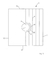
- the field 3 is here trapezoidal with the corners 45 - 48 formed. This results in two section boundaries 41 and 43, which extend in the extension through the central point Z and enclose the angle ⁇ with each other. Furthermore, it can be seen that the trapezoidal field 3 has a narrow side 42 and a broad side 44, which respectively connect the corresponding end points 45, 46 and 47, 48. These are used to calculate the minimum and maximum number of furrows.
- the plow 1 is currently at a position P. This was determined with a satellite-based positioning system (GPS system). According to steps 106-109 of the method described above 100, the distance D along the circular arc B around the central point Z is calculated, and the working width A is calculated by means of the furrow number still to be plowed (towards the section boundary 41).
- GPS system satellite-based positioning system
- Fig. 3 shows a further embodiment, in which the field 3 has a complex polygon shape. It can be seen that the field 3 has the four sections 4, 5, 6 and 7, which are each formed as a quadrangle. On the field 3 is the plow (not shown here) at the plow position P. In order to plow a particularly large area parallel, the main section 5 is rectangular with two mutually parallel main section boundaries 51 and 53 selected. On a display unit, it is possible for the user to set the two main section boundaries 51 and 53 as needed (in the Fig. 3 to the left and right).
- the section 4 is formed as an edge section and has two mutually angled edge section boundaries 41 and 43.
- the edge portion boundary 41 coincides with the main portion boundary 53.
- the edge portion 4 is defined by the vertices 45-48 as a quadrilateral.
- the two straight section boundaries 41 and 43 extend in their extension through the first central point Z 1 .
- the narrow sides 42 and the broad side 44 can be seen, over which the total number of furrows to be plowed in the section 4 is calculated.
- the working width and the furrows in the edge portion 4 are determined in the same way as previously with respect to Fig. 1 and 2 described.
- the central point Z 2 of the section 6 is determined by the extension of the section boundaries 61 and 63 as an intersection. Furthermore, the central point Z 3 of the section 7 as the intersection of the extended Section boundaries 71 and 73 determined.
- the section boundaries 63 and 73 coincide with the main section boundary 51, respectively.
- the first distance d 1 of the plow position P to the central point Z 1 is calculated. Subsequently, the first distance d 1 is compared with the third distance d 3 . If the first distance d 1 is greater than the third distance d 3 , another central point is selected. Also, another central point is selected if the first distance d 1 is smaller than the second distance d 2 . This calculation also applies to sections 6 and 7. If no central point can be prioritized with this calculation, then the plow is either outside the field or within the main section 5 with a uniform working width.
- the working width calculation is then performed according to steps 106 - 109 in FIG Fig. 1 carried out.
- Fig. 5 is a further embodiment of the method in the bypass of an obstacle 9 shown in a plan view. It can be seen that the section 5 is rectangular and has two section boundaries 51, 53 as well as the narrow and the wide side 52, 54. In this particular case, the narrow side 52 is the same length as the wide side 54.
- the furrows 81 and 82 are guided around the obstacle 9, the working width of the plow at position P being adjusted with a correction calculation.
- a compensation number is calculated, which represents the number of furrows needed after the obstacle avoidance to completely retrace the lane completely. Furthermore, with this compensation number continuously the working width can be corrected in the obstacle drive.
- the compensation number is calculated as follows: First, a minimum distance is calculated by reducing the length of the narrowest side 52 about the obstacle diameter C.
- the compensation number is calculated, which indicates the number of required furrows which is necessary in the event of an obstacle avoidance for the purpose of reestablishing a straight furrow.
- a control unit having an interface for detecting the plow position P by means of the locating system and which is designed to carry out the method 100 according to at least one of claims 1-14.
Landscapes
- Life Sciences & Earth Sciences (AREA)
- Engineering & Computer Science (AREA)
- Mechanical Engineering (AREA)
- Soil Sciences (AREA)
- Environmental Sciences (AREA)
- Guiding Agricultural Machines (AREA)
- Lifting Devices For Agricultural Implements (AREA)
Applications Claiming Priority (1)
| Application Number | Priority Date | Filing Date | Title |
|---|---|---|---|
| DE102014102030.8A DE102014102030A1 (de) | 2014-02-18 | 2014-02-18 | Verfahren und Steuerungseinheit zur Einstellung einer Arbeitsbreite eines Pflugs |
Publications (3)
| Publication Number | Publication Date |
|---|---|
| EP2918155A2 true EP2918155A2 (fr) | 2015-09-16 |
| EP2918155A3 EP2918155A3 (fr) | 2015-11-18 |
| EP2918155B1 EP2918155B1 (fr) | 2019-05-29 |
Family
ID=52633201
Family Applications (1)
| Application Number | Title | Priority Date | Filing Date |
|---|---|---|---|
| EP15401007.8A Active EP2918155B1 (fr) | 2014-02-18 | 2015-02-17 | Procédé et unité de commande destinés au réglage d'une largeur de travail d'une charrue |
Country Status (2)
| Country | Link |
|---|---|
| EP (1) | EP2918155B1 (fr) |
| DE (1) | DE102014102030A1 (fr) |
Cited By (2)
| Publication number | Priority date | Publication date | Assignee | Title |
|---|---|---|---|---|
| WO2018166561A1 (fr) | 2017-03-17 | 2018-09-20 | Lemken Gmbh & Co Kg | Procédé pour planifier le travail d'un champ agricole |
| EP4118943A1 (fr) * | 2021-07-15 | 2023-01-18 | CLAAS E-Systems GmbH | Procédé de planification d'un itinéraire de traitement d'un champ d'un engin de travail agricole |
Families Citing this family (3)
| Publication number | Priority date | Publication date | Assignee | Title |
|---|---|---|---|---|
| DE102021132869A1 (de) | 2021-12-14 | 2023-06-15 | Amazonen-Werke H. Dreyer SE & Co. KG | Verfahren zum Ermitteln von Korrektureinstellungen für einen landwirtschaftlichen Pflug |
| DE102022107924A1 (de) | 2022-04-04 | 2023-10-05 | Amazonen-Werke H. Dreyer SE & Co. KG | Verfahren zum Betreiben eines landwirtschaftlichen Maschinensystems und landwirtschaftliches Maschinensystem zum Bearbeiten einer landwirtschaftlichen Nutzfläche |
| DE102023129964A1 (de) * | 2023-10-30 | 2025-04-30 | Lemken Gmbh & Co. Kg | Verfahren zum Betreiben eines lenkbaren, eine veränderbare Arbeitsbreite aufweisenden landwirtschaftlichen Arbeitsgerätes |
Citations (2)
| Publication number | Priority date | Publication date | Assignee | Title |
|---|---|---|---|---|
| DE102004027242A1 (de) | 2004-06-03 | 2005-12-22 | Claas Selbstfahrende Erntemaschinen Gmbh | Routenplanungssystem für landwirtschaftliche Arbeitsmaschinen |
| EP2446725B1 (fr) | 2010-10-26 | 2013-07-31 | Deere & Company | Système et procédé de détermination du chemin prévu d'un véhicule |
Family Cites Families (2)
| Publication number | Priority date | Publication date | Assignee | Title |
|---|---|---|---|---|
| US7689356B2 (en) * | 2006-10-27 | 2010-03-30 | Cnh America Llc | Method and apparatus for creating curved swath patterns for farm machinery |
| US7706948B2 (en) * | 2007-03-02 | 2010-04-27 | Cnh America Llc | Method for creating spiral swaths for irregular field boundaries |
-
2014
- 2014-02-18 DE DE102014102030.8A patent/DE102014102030A1/de not_active Withdrawn
-
2015
- 2015-02-17 EP EP15401007.8A patent/EP2918155B1/fr active Active
Patent Citations (2)
| Publication number | Priority date | Publication date | Assignee | Title |
|---|---|---|---|---|
| DE102004027242A1 (de) | 2004-06-03 | 2005-12-22 | Claas Selbstfahrende Erntemaschinen Gmbh | Routenplanungssystem für landwirtschaftliche Arbeitsmaschinen |
| EP2446725B1 (fr) | 2010-10-26 | 2013-07-31 | Deere & Company | Système et procédé de détermination du chemin prévu d'un véhicule |
Cited By (3)
| Publication number | Priority date | Publication date | Assignee | Title |
|---|---|---|---|---|
| WO2018166561A1 (fr) | 2017-03-17 | 2018-09-20 | Lemken Gmbh & Co Kg | Procédé pour planifier le travail d'un champ agricole |
| DE102017105773A1 (de) | 2017-03-17 | 2018-09-20 | Lemken Gmbh & Co. Kg | Verfahren zum Planen der Bearbeitung eines landwirtschaftlichen Felds |
| EP4118943A1 (fr) * | 2021-07-15 | 2023-01-18 | CLAAS E-Systems GmbH | Procédé de planification d'un itinéraire de traitement d'un champ d'un engin de travail agricole |
Also Published As
| Publication number | Publication date |
|---|---|
| EP2918155B1 (fr) | 2019-05-29 |
| DE102014102030A1 (de) | 2015-08-20 |
| EP2918155A3 (fr) | 2015-11-18 |
Similar Documents
| Publication | Publication Date | Title |
|---|---|---|
| EP2918155B1 (fr) | Procédé et unité de commande destinés au réglage d'une largeur de travail d'une charrue | |
| EP2221702B1 (fr) | Procédé de production de bandes de circulation de référence pour des véhicules agricoles | |
| EP3363273A1 (fr) | Système de machine agricole et procédé de planification de voies de circulation permettant de traiter une surface agricole | |
| EP3595427B1 (fr) | Procédé pour planifier le travail d'un champ agricole | |
| DE102004027242A1 (de) | Routenplanungssystem für landwirtschaftliche Arbeitsmaschinen | |
| DE102006015203A1 (de) | Verfahren zur Steuerung von landwirtschaftlichen Maschinensystemen | |
| DE102009025438A1 (de) | Routenplanungsverfahren und -system | |
| EP3537863A1 (fr) | Procédé de génération de données de manière prédictive destiné à la commande d'une voie et d'une séquence de fonctionnement pour véhicules et machines agricoles | |
| DE112019005816T5 (de) | Lenksteuerungsanordnung, Verfahren zum Lenken eines Roboterwerkzeugs und verwandte Vorrichtungen | |
| EP2918157B2 (fr) | Machine agricole dotée d'une commande de section | |
| EP4245108A1 (fr) | Procédé d'optimisation d'itinéraire | |
| EP2957159A1 (fr) | Procédé de détermination de voies théoriques | |
| EP4118943B1 (fr) | Procédé de planification d'un itinéraire de traitement d'un champ d'un engin de travail agricole | |
| EP3732945B1 (fr) | Technique de la génération d'un profil de terrain à l'aide d'une machine agricole | |
| DE102017103139B4 (de) | Verfahren zur Bestimmung von Fahrspuren auf einer landwirtschaftlichen Fläche | |
| EP4052550B1 (fr) | Dispositif de compensation de la suspension latérale pour la viticulture | |
| DE102017103138B4 (de) | Verfahren zur Bestimmung von Fahrspuren auf einer landwirtschaftlichen Fläche | |
| DE102017103144B4 (de) | Verfahren und Vorrichtung zur Klassifizierung von Begrenzungsabschnitten einer landwirtschaftlichen Fläche | |
| DE102017103140B4 (de) | Verfahren und Vorrichtung zur Festlegung einer Bezugsachse auf einer landwirtschaftlichen Fläche | |
| EP3014969A1 (fr) | Procédé de commande d'un epandeur agricole sur une surface agricole | |
| DE102017103137B4 (de) | Verfahren zur Ermittlung von Vorgewendepositionen für eine landwirtschaftliche Fläche | |
| DE544439C (de) | Vorrichtung zum Anschliessen von landwirtschaftlichen Geraeten oder Arbeitsmaschinenan eine Zugmaschine | |
| EP1527670A2 (fr) | Méthode pour controller un dispositif de coupe monté sur un véhicule | |
| EP3403496B1 (fr) | Procédé de détermination d'une dose d'application requise pour un produit agricole | |
| DE102020207045A1 (de) | Schutz von landwirtschaftlichem Gerät |
Legal Events
| Date | Code | Title | Description |
|---|---|---|---|
| PUAI | Public reference made under article 153(3) epc to a published international application that has entered the european phase |
Free format text: ORIGINAL CODE: 0009012 |
|
| AK | Designated contracting states |
Kind code of ref document: A2 Designated state(s): AL AT BE BG CH CY CZ DE DK EE ES FI FR GB GR HR HU IE IS IT LI LT LU LV MC MK MT NL NO PL PT RO RS SE SI SK SM TR |
|
| AX | Request for extension of the european patent |
Extension state: BA ME |
|
| PUAL | Search report despatched |
Free format text: ORIGINAL CODE: 0009013 |
|
| AK | Designated contracting states |
Kind code of ref document: A3 Designated state(s): AL AT BE BG CH CY CZ DE DK EE ES FI FR GB GR HR HU IE IS IT LI LT LU LV MC MK MT NL NO PL PT RO RS SE SI SK SM TR |
|
| AX | Request for extension of the european patent |
Extension state: BA ME |
|
| RIC1 | Information provided on ipc code assigned before grant |
Ipc: A01B 3/24 20060101AFI20151012BHEP Ipc: A01B 3/36 20060101ALI20151012BHEP Ipc: A01B 69/00 20060101ALI20151012BHEP |
|
| RIN1 | Information on inventor provided before grant (corrected) |
Inventor name: FROESCHLE, HEIKE |
|
| 17P | Request for examination filed |
Effective date: 20160517 |
|
| RBV | Designated contracting states (corrected) |
Designated state(s): AL AT BE BG CH CY CZ DE DK EE ES FI FR GB GR HR HU IE IS IT LI LT LU LV MC MK MT NL NO PL PT RO RS SE SI SK SM TR |
|
| GRAP | Despatch of communication of intention to grant a patent |
Free format text: ORIGINAL CODE: EPIDOSNIGR1 |
|
| STAA | Information on the status of an ep patent application or granted ep patent |
Free format text: STATUS: GRANT OF PATENT IS INTENDED |
|
| INTG | Intention to grant announced |
Effective date: 20190218 |
|
| GRAS | Grant fee paid |
Free format text: ORIGINAL CODE: EPIDOSNIGR3 |
|
| GRAA | (expected) grant |
Free format text: ORIGINAL CODE: 0009210 |
|
| STAA | Information on the status of an ep patent application or granted ep patent |
Free format text: STATUS: THE PATENT HAS BEEN GRANTED |
|
| AK | Designated contracting states |
Kind code of ref document: B1 Designated state(s): AL AT BE BG CH CY CZ DE DK EE ES FI FR GB GR HR HU IE IS IT LI LT LU LV MC MK MT NL NO PL PT RO RS SE SI SK SM TR |
|
| REG | Reference to a national code |
Ref country code: GB Ref legal event code: FG4D Free format text: NOT ENGLISH |
|
| REG | Reference to a national code |
Ref country code: CH Ref legal event code: EP |
|
| REG | Reference to a national code |
Ref country code: AT Ref legal event code: REF Ref document number: 1137688 Country of ref document: AT Kind code of ref document: T Effective date: 20190615 |
|
| REG | Reference to a national code |
Ref country code: DE Ref legal event code: R096 Ref document number: 502015009181 Country of ref document: DE |
|
| REG | Reference to a national code |
Ref country code: IE Ref legal event code: FG4D Free format text: LANGUAGE OF EP DOCUMENT: GERMAN |
|
| REG | Reference to a national code |
Ref country code: NO Ref legal event code: T2 Effective date: 20190529 |
|
| REG | Reference to a national code |
Ref country code: NL Ref legal event code: MP Effective date: 20190529 |
|
| REG | Reference to a national code |
Ref country code: LT Ref legal event code: MG4D |
|
| PG25 | Lapsed in a contracting state [announced via postgrant information from national office to epo] |
Ref country code: SE Free format text: LAPSE BECAUSE OF FAILURE TO SUBMIT A TRANSLATION OF THE DESCRIPTION OR TO PAY THE FEE WITHIN THE PRESCRIBED TIME-LIMIT Effective date: 20190529 Ref country code: ES Free format text: LAPSE BECAUSE OF FAILURE TO SUBMIT A TRANSLATION OF THE DESCRIPTION OR TO PAY THE FEE WITHIN THE PRESCRIBED TIME-LIMIT Effective date: 20190529 Ref country code: PT Free format text: LAPSE BECAUSE OF FAILURE TO SUBMIT A TRANSLATION OF THE DESCRIPTION OR TO PAY THE FEE WITHIN THE PRESCRIBED TIME-LIMIT Effective date: 20190930 Ref country code: LT Free format text: LAPSE BECAUSE OF FAILURE TO SUBMIT A TRANSLATION OF THE DESCRIPTION OR TO PAY THE FEE WITHIN THE PRESCRIBED TIME-LIMIT Effective date: 20190529 Ref country code: FI Free format text: LAPSE BECAUSE OF FAILURE TO SUBMIT A TRANSLATION OF THE DESCRIPTION OR TO PAY THE FEE WITHIN THE PRESCRIBED TIME-LIMIT Effective date: 20190529 Ref country code: AL Free format text: LAPSE BECAUSE OF FAILURE TO SUBMIT A TRANSLATION OF THE DESCRIPTION OR TO PAY THE FEE WITHIN THE PRESCRIBED TIME-LIMIT Effective date: 20190529 Ref country code: HR Free format text: LAPSE BECAUSE OF FAILURE TO SUBMIT A TRANSLATION OF THE DESCRIPTION OR TO PAY THE FEE WITHIN THE PRESCRIBED TIME-LIMIT Effective date: 20190529 |
|
| PG25 | Lapsed in a contracting state [announced via postgrant information from national office to epo] |
Ref country code: GR Free format text: LAPSE BECAUSE OF FAILURE TO SUBMIT A TRANSLATION OF THE DESCRIPTION OR TO PAY THE FEE WITHIN THE PRESCRIBED TIME-LIMIT Effective date: 20190830 Ref country code: LV Free format text: LAPSE BECAUSE OF FAILURE TO SUBMIT A TRANSLATION OF THE DESCRIPTION OR TO PAY THE FEE WITHIN THE PRESCRIBED TIME-LIMIT Effective date: 20190529 Ref country code: BG Free format text: LAPSE BECAUSE OF FAILURE TO SUBMIT A TRANSLATION OF THE DESCRIPTION OR TO PAY THE FEE WITHIN THE PRESCRIBED TIME-LIMIT Effective date: 20190829 Ref country code: RS Free format text: LAPSE BECAUSE OF FAILURE TO SUBMIT A TRANSLATION OF THE DESCRIPTION OR TO PAY THE FEE WITHIN THE PRESCRIBED TIME-LIMIT Effective date: 20190529 |
|
| PG25 | Lapsed in a contracting state [announced via postgrant information from national office to epo] |
Ref country code: DK Free format text: LAPSE BECAUSE OF FAILURE TO SUBMIT A TRANSLATION OF THE DESCRIPTION OR TO PAY THE FEE WITHIN THE PRESCRIBED TIME-LIMIT Effective date: 20190529 Ref country code: NL Free format text: LAPSE BECAUSE OF FAILURE TO SUBMIT A TRANSLATION OF THE DESCRIPTION OR TO PAY THE FEE WITHIN THE PRESCRIBED TIME-LIMIT Effective date: 20190529 Ref country code: EE Free format text: LAPSE BECAUSE OF FAILURE TO SUBMIT A TRANSLATION OF THE DESCRIPTION OR TO PAY THE FEE WITHIN THE PRESCRIBED TIME-LIMIT Effective date: 20190529 Ref country code: CZ Free format text: LAPSE BECAUSE OF FAILURE TO SUBMIT A TRANSLATION OF THE DESCRIPTION OR TO PAY THE FEE WITHIN THE PRESCRIBED TIME-LIMIT Effective date: 20190529 Ref country code: RO Free format text: LAPSE BECAUSE OF FAILURE TO SUBMIT A TRANSLATION OF THE DESCRIPTION OR TO PAY THE FEE WITHIN THE PRESCRIBED TIME-LIMIT Effective date: 20190529 Ref country code: SK Free format text: LAPSE BECAUSE OF FAILURE TO SUBMIT A TRANSLATION OF THE DESCRIPTION OR TO PAY THE FEE WITHIN THE PRESCRIBED TIME-LIMIT Effective date: 20190529 |
|
| PG25 | Lapsed in a contracting state [announced via postgrant information from national office to epo] |
Ref country code: SM Free format text: LAPSE BECAUSE OF FAILURE TO SUBMIT A TRANSLATION OF THE DESCRIPTION OR TO PAY THE FEE WITHIN THE PRESCRIBED TIME-LIMIT Effective date: 20190529 Ref country code: IT Free format text: LAPSE BECAUSE OF FAILURE TO SUBMIT A TRANSLATION OF THE DESCRIPTION OR TO PAY THE FEE WITHIN THE PRESCRIBED TIME-LIMIT Effective date: 20190529 |
|
| REG | Reference to a national code |
Ref country code: DE Ref legal event code: R097 Ref document number: 502015009181 Country of ref document: DE |
|
| PG25 | Lapsed in a contracting state [announced via postgrant information from national office to epo] |
Ref country code: TR Free format text: LAPSE BECAUSE OF FAILURE TO SUBMIT A TRANSLATION OF THE DESCRIPTION OR TO PAY THE FEE WITHIN THE PRESCRIBED TIME-LIMIT Effective date: 20190529 |
|
| PLBE | No opposition filed within time limit |
Free format text: ORIGINAL CODE: 0009261 |
|
| STAA | Information on the status of an ep patent application or granted ep patent |
Free format text: STATUS: NO OPPOSITION FILED WITHIN TIME LIMIT |
|
| PG25 | Lapsed in a contracting state [announced via postgrant information from national office to epo] |
Ref country code: PL Free format text: LAPSE BECAUSE OF FAILURE TO SUBMIT A TRANSLATION OF THE DESCRIPTION OR TO PAY THE FEE WITHIN THE PRESCRIBED TIME-LIMIT Effective date: 20190529 |
|
| 26N | No opposition filed |
Effective date: 20200303 |
|
| PG25 | Lapsed in a contracting state [announced via postgrant information from national office to epo] |
Ref country code: SI Free format text: LAPSE BECAUSE OF FAILURE TO SUBMIT A TRANSLATION OF THE DESCRIPTION OR TO PAY THE FEE WITHIN THE PRESCRIBED TIME-LIMIT Effective date: 20190529 |
|
| REG | Reference to a national code |
Ref country code: CH Ref legal event code: PL |
|
| GBPC | Gb: european patent ceased through non-payment of renewal fee |
Effective date: 20200217 |
|
| REG | Reference to a national code |
Ref country code: BE Ref legal event code: MM Effective date: 20200229 |
|
| PG25 | Lapsed in a contracting state [announced via postgrant information from national office to epo] |
Ref country code: MC Free format text: LAPSE BECAUSE OF FAILURE TO SUBMIT A TRANSLATION OF THE DESCRIPTION OR TO PAY THE FEE WITHIN THE PRESCRIBED TIME-LIMIT Effective date: 20190529 Ref country code: LU Free format text: LAPSE BECAUSE OF NON-PAYMENT OF DUE FEES Effective date: 20200217 |
|
| PG25 | Lapsed in a contracting state [announced via postgrant information from national office to epo] |
Ref country code: CH Free format text: LAPSE BECAUSE OF NON-PAYMENT OF DUE FEES Effective date: 20200229 Ref country code: LI Free format text: LAPSE BECAUSE OF NON-PAYMENT OF DUE FEES Effective date: 20200229 |
|
| PG25 | Lapsed in a contracting state [announced via postgrant information from national office to epo] |
Ref country code: IE Free format text: LAPSE BECAUSE OF NON-PAYMENT OF DUE FEES Effective date: 20200217 Ref country code: GB Free format text: LAPSE BECAUSE OF NON-PAYMENT OF DUE FEES Effective date: 20200217 |
|
| PG25 | Lapsed in a contracting state [announced via postgrant information from national office to epo] |
Ref country code: BE Free format text: LAPSE BECAUSE OF NON-PAYMENT OF DUE FEES Effective date: 20200229 |
|
| REG | Reference to a national code |
Ref country code: DE Ref legal event code: R081 Ref document number: 502015009181 Country of ref document: DE Owner name: AMAZONEN-WERKE H. DREYER SE & CO. KG, DE Free format text: FORMER OWNER: AMAZONEN-WERKE H. DREYER GMBH & CO. KG, 49205 HASBERGEN, DE |
|
| PG25 | Lapsed in a contracting state [announced via postgrant information from national office to epo] |
Ref country code: MT Free format text: LAPSE BECAUSE OF FAILURE TO SUBMIT A TRANSLATION OF THE DESCRIPTION OR TO PAY THE FEE WITHIN THE PRESCRIBED TIME-LIMIT Effective date: 20190529 Ref country code: CY Free format text: LAPSE BECAUSE OF FAILURE TO SUBMIT A TRANSLATION OF THE DESCRIPTION OR TO PAY THE FEE WITHIN THE PRESCRIBED TIME-LIMIT Effective date: 20190529 |
|
| PG25 | Lapsed in a contracting state [announced via postgrant information from national office to epo] |
Ref country code: MK Free format text: LAPSE BECAUSE OF FAILURE TO SUBMIT A TRANSLATION OF THE DESCRIPTION OR TO PAY THE FEE WITHIN THE PRESCRIBED TIME-LIMIT Effective date: 20190529 Ref country code: IS Free format text: LAPSE BECAUSE OF FAILURE TO SUBMIT A TRANSLATION OF THE DESCRIPTION OR TO PAY THE FEE WITHIN THE PRESCRIBED TIME-LIMIT Effective date: 20190929 |
|
| P01 | Opt-out of the competence of the unified patent court (upc) registered |
Effective date: 20230523 |
|
| PGFP | Annual fee paid to national office [announced via postgrant information from national office to epo] |
Ref country code: FR Payment date: 20251208 Year of fee payment: 12 |
|
| PGFP | Annual fee paid to national office [announced via postgrant information from national office to epo] |
Ref country code: DE Payment date: 20251224 Year of fee payment: 12 Ref country code: NO Payment date: 20260211 Year of fee payment: 12 |
|
| PGFP | Annual fee paid to national office [announced via postgrant information from national office to epo] |
Ref country code: AT Payment date: 20260127 Year of fee payment: 12 |