EP2918249A2 - Système de cathéter supra-claviculaire pour un accès transseptal à l'oreillette gauche et ventricule gauche - Google Patents
Système de cathéter supra-claviculaire pour un accès transseptal à l'oreillette gauche et ventricule gauche Download PDFInfo
- Publication number
- EP2918249A2 EP2918249A2 EP15158051.1A EP15158051A EP2918249A2 EP 2918249 A2 EP2918249 A2 EP 2918249A2 EP 15158051 A EP15158051 A EP 15158051A EP 2918249 A2 EP2918249 A2 EP 2918249A2
- Authority
- EP
- European Patent Office
- Prior art keywords
- catheter
- mitral valve
- guide
- positioning
- distal end
- Prior art date
- Legal status (The legal status is an assumption and is not a legal conclusion. Google has not performed a legal analysis and makes no representation as to the accuracy of the status listed.)
- Granted
Links
Images





Classifications
-
- A—HUMAN NECESSITIES
- A61—MEDICAL OR VETERINARY SCIENCE; HYGIENE
- A61F—FILTERS IMPLANTABLE INTO BLOOD VESSELS; PROSTHESES; DEVICES PROVIDING PATENCY TO, OR PREVENTING COLLAPSING OF, TUBULAR STRUCTURES OF THE BODY, e.g. STENTS; ORTHOPAEDIC, NURSING OR CONTRACEPTIVE DEVICES; FOMENTATION; TREATMENT OR PROTECTION OF EYES OR EARS; BANDAGES, DRESSINGS OR ABSORBENT PADS; FIRST-AID KITS
- A61F2/00—Filters implantable into blood vessels; Prostheses, i.e. artificial substitutes or replacements for parts of the body; Appliances for connecting them with the body; Devices providing patency to, or preventing collapsing of, tubular structures of the body, e.g. stents
- A61F2/02—Prostheses implantable into the body
- A61F2/24—Heart valves ; Vascular valves, e.g. venous valves; Heart implants, e.g. passive devices for improving the function of the native valve or the heart muscle; Transmyocardial revascularisation [TMR] devices; Valves implantable in the body
- A61F2/2427—Devices for manipulating or deploying heart valves during implantation
-
- A—HUMAN NECESSITIES
- A61—MEDICAL OR VETERINARY SCIENCE; HYGIENE
- A61F—FILTERS IMPLANTABLE INTO BLOOD VESSELS; PROSTHESES; DEVICES PROVIDING PATENCY TO, OR PREVENTING COLLAPSING OF, TUBULAR STRUCTURES OF THE BODY, e.g. STENTS; ORTHOPAEDIC, NURSING OR CONTRACEPTIVE DEVICES; FOMENTATION; TREATMENT OR PROTECTION OF EYES OR EARS; BANDAGES, DRESSINGS OR ABSORBENT PADS; FIRST-AID KITS
- A61F2/00—Filters implantable into blood vessels; Prostheses, i.e. artificial substitutes or replacements for parts of the body; Appliances for connecting them with the body; Devices providing patency to, or preventing collapsing of, tubular structures of the body, e.g. stents
- A61F2/0063—Implantable repair or support meshes, e.g. hernia meshes
-
- A—HUMAN NECESSITIES
- A61—MEDICAL OR VETERINARY SCIENCE; HYGIENE
- A61B—DIAGNOSIS; SURGERY; IDENTIFICATION
- A61B17/00—Surgical instruments, devices or methods
- A61B17/00234—Surgical instruments, devices or methods for minimally invasive surgery
- A61B2017/00238—Type of minimally invasive operation
- A61B2017/00243—Type of minimally invasive operation cardiac
-
- A—HUMAN NECESSITIES
- A61—MEDICAL OR VETERINARY SCIENCE; HYGIENE
- A61B—DIAGNOSIS; SURGERY; IDENTIFICATION
- A61B17/00—Surgical instruments, devices or methods
- A61B17/0057—Implements for plugging an opening in the wall of a hollow or tubular organ, e.g. for sealing a vessel puncture or closing a cardiac septal defect
- A61B2017/00575—Implements for plugging an opening in the wall of a hollow or tubular organ, e.g. for sealing a vessel puncture or closing a cardiac septal defect for closure at remote site, e.g. closing atrial septum defects
- A61B2017/00597—Implements comprising a membrane
-
- A—HUMAN NECESSITIES
- A61—MEDICAL OR VETERINARY SCIENCE; HYGIENE
- A61B—DIAGNOSIS; SURGERY; IDENTIFICATION
- A61B17/00—Surgical instruments, devices or methods
- A61B17/0057—Implements for plugging an opening in the wall of a hollow or tubular organ, e.g. for sealing a vessel puncture or closing a cardiac septal defect
- A61B2017/00575—Implements for plugging an opening in the wall of a hollow or tubular organ, e.g. for sealing a vessel puncture or closing a cardiac septal defect for closure at remote site, e.g. closing atrial septum defects
- A61B2017/0061—Implements located only on one side of the opening
-
- A—HUMAN NECESSITIES
- A61—MEDICAL OR VETERINARY SCIENCE; HYGIENE
- A61B—DIAGNOSIS; SURGERY; IDENTIFICATION
- A61B17/00—Surgical instruments, devices or methods
- A61B17/0057—Implements for plugging an opening in the wall of a hollow or tubular organ, e.g. for sealing a vessel puncture or closing a cardiac septal defect
- A61B2017/00646—Type of implements
- A61B2017/00659—Type of implements located only on one side of the opening
-
- A—HUMAN NECESSITIES
- A61—MEDICAL OR VETERINARY SCIENCE; HYGIENE
- A61B—DIAGNOSIS; SURGERY; IDENTIFICATION
- A61B17/00—Surgical instruments, devices or methods
- A61B17/12—Surgical instruments, devices or methods for ligaturing or otherwise compressing tubular parts of the body, e.g. blood vessels or umbilical cord
- A61B17/12022—Occluding by internal devices, e.g. balloons or releasable wires
- A61B2017/1205—Introduction devices
- A61B2017/12054—Details concerning the detachment of the occluding device from the introduction device
- A61B2017/12081—Details concerning the detachment of the occluding device from the introduction device detachable by inflation
-
- A—HUMAN NECESSITIES
- A61—MEDICAL OR VETERINARY SCIENCE; HYGIENE
- A61F—FILTERS IMPLANTABLE INTO BLOOD VESSELS; PROSTHESES; DEVICES PROVIDING PATENCY TO, OR PREVENTING COLLAPSING OF, TUBULAR STRUCTURES OF THE BODY, e.g. STENTS; ORTHOPAEDIC, NURSING OR CONTRACEPTIVE DEVICES; FOMENTATION; TREATMENT OR PROTECTION OF EYES OR EARS; BANDAGES, DRESSINGS OR ABSORBENT PADS; FIRST-AID KITS
- A61F2/00—Filters implantable into blood vessels; Prostheses, i.e. artificial substitutes or replacements for parts of the body; Appliances for connecting them with the body; Devices providing patency to, or preventing collapsing of, tubular structures of the body, e.g. stents
- A61F2/02—Prostheses implantable into the body
- A61F2/24—Heart valves ; Vascular valves, e.g. venous valves; Heart implants, e.g. passive devices for improving the function of the native valve or the heart muscle; Transmyocardial revascularisation [TMR] devices; Valves implantable in the body
- A61F2/2427—Devices for manipulating or deploying heart valves during implantation
- A61F2/243—Deployment by mechanical expansion
- A61F2/2433—Deployment by mechanical expansion using balloon catheter
-
- A—HUMAN NECESSITIES
- A61—MEDICAL OR VETERINARY SCIENCE; HYGIENE
- A61F—FILTERS IMPLANTABLE INTO BLOOD VESSELS; PROSTHESES; DEVICES PROVIDING PATENCY TO, OR PREVENTING COLLAPSING OF, TUBULAR STRUCTURES OF THE BODY, e.g. STENTS; ORTHOPAEDIC, NURSING OR CONTRACEPTIVE DEVICES; FOMENTATION; TREATMENT OR PROTECTION OF EYES OR EARS; BANDAGES, DRESSINGS OR ABSORBENT PADS; FIRST-AID KITS
- A61F2210/00—Particular material properties of prostheses classified in groups A61F2/00 - A61F2/26 or A61F2/82 or A61F9/00 or A61F11/00 or subgroups thereof
- A61F2210/0004—Particular material properties of prostheses classified in groups A61F2/00 - A61F2/26 or A61F2/82 or A61F9/00 or A61F11/00 or subgroups thereof bioabsorbable
-
- A—HUMAN NECESSITIES
- A61—MEDICAL OR VETERINARY SCIENCE; HYGIENE
- A61F—FILTERS IMPLANTABLE INTO BLOOD VESSELS; PROSTHESES; DEVICES PROVIDING PATENCY TO, OR PREVENTING COLLAPSING OF, TUBULAR STRUCTURES OF THE BODY, e.g. STENTS; ORTHOPAEDIC, NURSING OR CONTRACEPTIVE DEVICES; FOMENTATION; TREATMENT OR PROTECTION OF EYES OR EARS; BANDAGES, DRESSINGS OR ABSORBENT PADS; FIRST-AID KITS
- A61F2230/00—Geometry of prostheses classified in groups A61F2/00 - A61F2/26 or A61F2/82 or A61F9/00 or A61F11/00 or subgroups thereof
- A61F2230/0002—Two-dimensional shapes, e.g. cross-sections
- A61F2230/0028—Shapes in the form of latin or greek characters
- A61F2230/0041—J-shaped
Definitions
- the present invention relates to catheters according to the preambles of claims 1, 5, 16 and 18 and a set according to the preamble of claim 19. It further relates to a method according to the preamble of claim 21.
- the present invention relates to catheters for replacement of native mitral valves with artificial mitral valves, also referred to herein as mitral valve implants or mitral valve prostheses.
- Access to the catheter is usually via the femoral artery. Since the femoral artery has only a moderately large diameter, the catheters used must not be thicker than about 28 Fr. ("French"). If the femoral matter is diseased or too thin, then alternatively the transapical access via the apex of the heart can be chosen.
- Fr. Fr.
- valve prostheses folded on the catheter currently have a diameter of about 21 Fr.
- transapical the apex of the heart
- transfemoral the inguinal vessels
- the mitral valve prosthesis can be inserted over the apex of the heart.
- the access to the apex is easy to produce, a catheter of up to 40 Fr. can be inserted without difficulty.
- the valve prosthesis is introduced into the native valve apparatus via the ventricle, the tendon threads present there can make the correct positioning of the heart valve difficult.
- the mitral valve prosthesis can be inserted via the inguinal vein, the femoral vein.
- the femoral vein has a sufficient diameter that allows larger catheters to be inserted as necessary in the case of the mitral valve prosthesis.
- the mitral valve catheter must be guided via the superior vena cava to the atrial septum, the interatrial septum and the heart. There, the atrial septum is opened by means of a puncture and the catheter is guided from the right atrium into the left atrium. In the left atrium, the tip of the catheter must curve more than 270 ° relative to other portions of the catheter so that the tip of the catheter can be inserted into the native mitral valve apparatus, together with the collapsed mitral valve prosthesis detachably attached thereto.
- An object of the present invention may be to propose devices by means of which a mitral valve prosthesis can also be implanted by means of a catheter.
- a corresponding method should be specified.
- the object according to the invention can be achieved by a guide catheter having the features of claim 1, by a positioning catheter having the features of claim 5, by a mitral valve catheter having the features of claim 16 and by a balloon catheter having the features of claim 18. It can also be achieved by a set having the features of claim 19 and by the method having the features of claim 21.
- a medical guide catheter for use in implanting an artificial mitral valve or for repair purposes relating to the heart.
- the guide catheter has a distal end portion and a proximal end portion.
- the distal end portion includes a distal end of the guide catheter.
- the proximal end portion includes a proximal end portion of the guide catheter.
- the guide catheter comprises a hollow designed guide portion.
- a guide section herein generally corresponds to the hollow, elongate interior, that is, the lumen, of the respective catheter which, in the case of the guide catheter according to the invention, extends continuously from the distal end or end section to the proximal end or end section.
- the guide portion of the guide catheter has or has a straight portion and a curved portion.
- the curved portion lies in the distal end region or forms the distal end.
- the curved portion is located distal to the straight portion.
- a hollow needle catheter can be advanced, with which the interatrial septum is punctured.
- the medical positioning catheter of the invention is also for use in implanting a mitral valve implant or repairing a heart defect or mitral valve.
- the positioning catheter has a distal end portion that includes a distal end of the positioning catheter and a proximal end portion that includes a proximal end of the positioning catheter.
- the positioning catheter also has a hollow guide section.
- the guide portion has or consists of a straight portion and at least a first curvature portion and a second curvature portion.
- the first curvature portion and the second curvature portion are in the distal end region.
- the first curvature portion or the second curvature portion form the distal end of the positioning catheter. Both the first curvature portion and the second curvature portion are disposed distally of the straight portion.
- the mitral valve medical catheter of the present invention is also for use in implanting a mitral valve implant. It has a distal end portion which includes a distal end of the mitral valve catheter and a proximal end portion which includes a proximal end of the mitral valve catheter.
- the mitral valve catheter according to the invention further comprises a receiving portion for receiving a mitral valve implant, to which a mitral valve implant is detachably connected.
- the medical balloon catheter according to the invention serves to prevent bleeding in the subcutaneous tissue. He has a balloon section. He also has a shell for the balloon section.
- the set or catheter system according to the invention has at least one guide catheter according to the invention.
- it has at least one of the following devices (and in turn each at least one piece): a hollow needle catheter, which carries at its end a likewise hollow needle; a positioning catheter according to the invention; a stylet; a balloon catheter according to the invention; a guidewire; and / or a mitral valve catheter according to the invention.
- the method of implanting a mitral valve prosthesis according to the invention comprises puncturing, preferably the venous angle of the subclavian vein and the internal jugular vein, in the region of its union with the brachiocephalic vein, or the brachiocephalic vein; the introduction of the guiding catheter according to the invention via the puncture site, further over the brachiocephalic vein and the superior vena cava, with the tip or opening of the guide catheter of the invention facing the interatrial septum or touching it; inserting a hollow or non-hollow guidewire or a hollow needle catheter, preferably into the guiding catheter, for penetrating the interatrial septum; inserting a guidewire into the left atrium and through the punctured opening of the interatrial septum further into the left atrium, preferably via the guiding catheter; inserting the inventive positioning catheter through the created opening of the interatrial septum over the guidewire into the brachiocephalic vein and the superior vena cava and transseptally into the left at
- the method according to the invention comprises dilating the opening created by means of a hollow needle or other tool in the interatrial septum.
- vein angle this can be understood as the area in which the subclavian vein and the internal jugular vein join together to form the brachiocephalic vein. If the venous angle is punctured, this can be understood as an example of puncturing of any of the vessels in the region of the union.
- distal and proximal refer to the use of the subject catheter.
- proximal end of each catheter is in doubt always in the upper part of the figure, while the distal end is in doubt always in the lower part of the figure. In Fig. 5 and Fig. 5a this is the other way around.
- Embodiments of the invention may have one or more of the following features in any combination, unless a specific combination for the skilled person is not as obviously technically impossible to detect.
- the subject matters of the subclaims also indicate embodiments according to the invention.
- the guide catheter is no longer than 30 cm or at most 40 cm.
- the guide catheter is not flexible, at least in use. He can be stiff or rigid.
- a catheter which can be pushed transfemally into the heart with regard to its flexibility can generally be considered flexible.
- Non-flexible may be a catheter whose flexibility does not permit or permit it.
- a rigid catheter may be understood in certain embodiments to be non-flexible.
- the guide catheter is made of plastic, others in metal, or includes such material. His material is preferably biocompatible.
- the curved section causes a bending or curvature of the guide section by 15 to 90 °, preferably by 20 to 30 °.
- the guide catheter or its guide section is a maximum of 80 cm, preferably a maximum of 60 cm, more preferably not more than 45 cm long. This allows more comfortable handling for the doctor, in particular in the case of a stiffer design of the guide catheter.
- the guiding catheter is rigid. It can ensure that the desired puncture site on the interatrial septum can be reached by its rigidity and the slight bending of its distal end region or its distal tip. Achievable may mean that the opening plane of the guide catheter is at as small an angle as possible to a puncturable surface of the intra-anal septum.
- the guiding catheter is radiopaque.
- the position of the guide catheter and in particular its opening of the guide section at its distal end can thus be monitored or monitored by means of fluoroscopy.
- the guide catheter is sufficiently rigid to be neither flexible nor flexible or resilient, completely, or at least in its straight section, in and / or through its use.
- the guide catheter is configured with a control mechanism by means of which the curvature of the curved section is actively adjustable.
- the guide catheter can thus in turn be introduced more or less straight. It can then be controlled by means of the control mechanism with the curvature described herein be curved to eventually stand with its outlet or opening as desired against the interatrial septum or directed.
- the guiding catheter guiding portion has a lumen of 14-45 Fr.
- the guide catheter has a valve and / or tube at the proximal outer end for venting, injecting, and inserting a guidewire.
- the guiding catheter is coated to allow easy sliding, e.g. As with silicone, hydrogel for better sliding and / or drugs or agents such as chlorhexidine or antibiotics and materials such as silver to reduce the risk of infection.
- the positioning catheter has a valve that closes the straight portion proximally.
- the first curvature section and the second curvature section of the positioning catheter are curved in opposite directions, in particular with respect to a plane.
- “Opposing” can refer to the sign of the curvature (plus, minus) or the angle of curvature.
- “Opposite” can, for example, in visual representation of the plane in which the curvatures lie, as convex versus concave or to be understood as “left” versus "right”.
- the first curvature portion of the positioning catheter causes bending or curvature of the guide portion by 10 ° to 120 °, preferably 90 ° to 120 °.
- the second curvature portion of the positioning catheter causes bending or curving of the guide portion by 0 ° (or 1 °) to 120 °, preferably 20 ° to 40 °.
- the positioning catheter or its guide section is at most 80 cm, preferably at most 60 cm, particularly preferably at most 45 cm long.
- the positioning catheter or its guide portion is non-flexible, non-elastic or rigid.
- the positioning catheter, its guide portion, the first curvature portion, and / or the second curvature portion have or have a shape-memory function, shape memory material, or the like.
- the positioning catheter further includes Valve, which closes the straight section to the proximal end.
- the positioning catheter removably carries a mitral valve implant in its distal end region. He has for this purpose a receiving portion for receiving the mitral valve implant.
- the flow direction of the mitral valve implant when present on the positioning catheter, extends from the proximal end portion to the distal end portion of the position catheter.
- the direction of flow of the mitral valve implant When referring to the direction of flow of the mitral valve implant herein, it may be understood as the direction in which the valves of the implant allow flow after implantation, which would not or should not permit them in the implanted state in the direction opposite thereto.
- the direction of flow therefore adheres immutably to the implant, regardless of whether it is implanted or still present on the catheter, regardless of whether blood actually flows through it or not yet.
- the flow direction of the mitral valve implant 600 runs Fig. 6e and 6f based on the figure from top to bottom.
- the flow direction is a structural property of the implant in the sense of a direction in which the implant can be flowed through.
- the flow direction of the mitral valve graft, when on the mitral valve catheter, is in the direction of flow is present, from the proximal end region to the distal end region of the mitral valve catheter.
- the flexible hollow needle catheter has an outer diameter which is smaller than an inner diameter of the guide portion of the guide catheter according to the invention.
- the method includes inserting a balloon catheter into the subcutaneous tissue prior to the puncture site of the brachiocephalic vein and expanding its balloon portion there.
- the hollow needle catheter preferably has at its distal end a needle which has a cutting edge or edge of solid and / or sharp-edged plastic or metal.
- the needle is preferably no longer than 5 mm to 10 mm.
- the hollow needle catheter or portion thereof, such as its needle, if provided, or a portion thereof, is radiopaque.
- the position of the hollow needle catheter can thus be monitored or monitored.
- the hollow needle catheter is referred to as this also preferably has a guide portion, which is hollow and through which a guide wire can be advanced.
- the guiding catheter guiding portion is thick enough to allow the hollow needle catheter to pass therethrough.
- the positioning catheter is designated herein as either locating the mitral valve graft in the region of the native mitral valve to be replaced, or as having a mitral valve catheter in it, which in turn supports the mitral valve graft, as required in the region of FIG replacing native mitral valve.
- the positioning catheter is configured to assume at least two states or shapes, namely a straight first shape or a straighter shape compared to the second shape, and a second shape in which the position catheter has curvature portions, or, measured at the first shape, curved portions.
- the positioning catheter can be easily introduced because straight.
- the positioning catheter can assume a double-curved shape in its distal end region, such as an S-shape.
- the double-curved shape makes it possible to bring the opening of the distal end as vertically as possible above the mitral valve annulus.
- the positioning catheter in certain embodiments of the invention, is configured to become straight or straight (ie, assume the first shape) when a straight or non-curved stylet is inserted into the guide portion of the guide portion of the positioning catheter. Its elasticity and / or its recovery properties allow this to be advantageous.
- the positioning catheter can thus be guided in a straight state over a guide wire in the left atrium in some of these embodiments.
- the catheter Upon retraction of the straight mandril, the catheter assumes its original, double-curved shape, which is, for example, an S-shape, such that its receiving section (if any) for the mitral valve implant or tip-in opening over which a mitral valve-carrying catheter penetrates the left atrium can be placed so as to lie in or above the native mitral valve apparatus that a mitral valve prosthesis can be conveniently positioned.
- the positioning catheter is configured with a control mechanism by means of which the curvature of the curved portion is actively adjustable.
- the positioning catheter can thus in turn be introduced more or less straight. It may then be curved by means of the control mechanism having the curvature described herein to eventually be positioned as desired.
- the positioning catheter is in certain embodiments of the invention, in view of its rather stiff character, optimal handling not more than 80 cm long (measured from its proximal end to its distal end), preferably between 45 and 60 cm long.
- the positioning catheter is suitable, and is also used to accomplish mitral valve repair.
- the tool required for this purpose can be advanced through the guide section of the positioning catheter to the native mitral valve.
- Other repairs are z. Grafting, implantation of a device to occlude the atrial ear, or a device to occlude an atrial or ventricular septal defect, insertion of a device to contract the left ventricle, or insertion of catheters to remove tumors of any pathology or thrombus into the left cardiac chambers.
- the balloon catheter according to the invention has a sheath which is at least partially provided over the balloon portion.
- the shell may comprise the usual biological or synthetic hemostats such as collagen or polylactate or the like, for which reason the shell is in These embodiments may also be referred to as a hemostatic sheath.
- the hemostatic material of the sheath is preferably bioresorbable.
- the balloon portion is configured and intended to be subcutaneously dilated by means of fluids. In this state, it displaces subcutaneous tissue and anchors itself in the puncture site.
- the balloon fluid can be vented, with the deflated balloon detaching from the optional shell, if the latter is provided.
- the sheath remains in the puncture wound after removal of the balloon.
- the guide catheter, the balloon catheter and / or the positioning catheter each have a guide portion with which they can be guided along a guide wire.
- the guide catheter and / or the positioning catheter have a valve at their respective proximal end. This advantageously serves to limit or completely prevent blood loss from the punctured vessel.
- the guiding catheter, the balloon catheter and / or the positioning catheter are sterilized, in particular by means of radiation, by means of steam and / or by means of temperature.
- the sterilization has preferably taken place factory. This allows cost-effective and automated sterilization that is less susceptible to human error.
- the balloon catheter and / or the positioning catheter are made of plastic, polymer, polyethylene, polypropylene, polyvinylchloride (PVC), or polyamide.
- the positioning catheter has an expandable inner diameter. This is possible by an elasticity of the tube or by unfolding the tube. Corresponding embodiments and devices can be provided. Thus, a thin-diameter positioning catheter can be inserted. When the larger diameter mitral valve graft is advanced over the flexible positioning catheter, the positioning catheter expands only a short distance, namely where the implant is lying, and only as long as it is advanced. As a result, the surrounding tissue is less stressed. More importantly, the flow of blood in the brachiocephalic vein and the superior vena cava is advantageously unaffected by the positioning catheter in place.
- the devices proposed by the invention allow for the first time a mitral valve implantation which is neither transfemoral nor transapical. In this case, due to the configuration of the device according to the invention, some of the difficulties mentioned in the implantation can be eliminated or at least mitigated.
- the devices according to the invention allow for the first time an implantation via a supraclavicular approach.
- Supraclavicular access can offer several key benefits. Among them is that there are clear landmarks for supraclavicular puncture compared to the subclavicular puncture. The puncture is made from the direction of the patient's head and not from the side.
- a catheter can be used, which at least until it reaches the right atrium of the heart, may run straight. Only to puncture the interatrial septum, he must be comparatively slightly curved.
- the benefits include that the distance to the lungs is greater than for subclavicular access, which reduces the risk of injury to the lungs.
- the guiding catheter which is used to prepare the puncture of the interatrial septum, advantageously allows easy, rapid puncture of the interatrial septum for straight supraclavicular access.
- the supraclavicular approach has considerable advantages, especially for the implantation of a catheter-supported valve prosthesis, which involves a percutaneous, i.
- Interventional implantation of a mitral valve prosthesis is possible by means of vascular puncture. It is a relatively straight path from the supraclavicular puncture site, via the venous angle, the brachiocepahlic vein and the superior vena cava to the right atrium and the interatrial septum. After penetrating the septum, the catheter only needs to be slightly bent to enter the left atrium. Again, only a slight bend is needed to enter the mitral valve apparatus.
- the distance from the puncture site to the mitral valve apparatus is very short at only about 15-20 cm.
- brachiocephalic vein already has a large diameter and after merging with the anterior vena cava, it widens further to the superior vena cava.
- the diameter of the brachiocephalic vein is large enough to accommodate catheters with a diameter of 40Fr. introduce.
- the supraclavicular approach allows insertion of a large caliber mitral valve catheter.
- the implantation can be controlled incomparably well, because the way to the native mitral valve apparatus is short and above all straight. No strong bending of the catheter is necessary to penetrate the native mitral valve apparatus.
- the subclavian vein In order to obtain a central venous access, the subclavian vein is usually punctured.
- the subclavian vein is below and behind the clavicle.
- This approach is commonly used to introduce a large catheter through which fluids and medications can be centrally delivered to the venous blood.
- this approach is also used to deliver pacemaker leads to the heart, or perform hemodialysis, to connect a heart-lung machine. This is possible because the subclavian vein has a large diameter and no venous valves.
- the subclavian vein has the same position in almost all patients and is therefore relatively safe to find and puncture.
- subclavian vein can not be used for access, e.g. after trauma, occlusion or lying pacemaker cables.
- the present invention allows for the first time to make use of the supraclavicular access due to the catheter according to the invention proposed herewith.
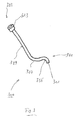
- Fig. 1 shows a guide catheter 100 according to the invention in a first embodiment.
- the guide catheter 100 has a distal end portion 103 and a proximal end portion 105.
- a hollowly shaped guide portion 107 Extending proximally to distally is a hollowly shaped guide portion 107. It corresponds to the continuous portion of the guide catheter 100 which has the hollow interior, that is, the lumen that extends from the distal end to the proximal end.
- the guide portion 107 has a straight portion 109 and a curved portion 111 or consists of these two portions 109, 111.
- the curved portion 109 is located in the distal end portion 103. In the Fig. 1 In other exemplary embodiments, which are not shown here, the curved portion 111 distantly reverts to another curvature, which adjoins the straight portion 109, in another exemplary embodiment shown in FIG equal preferably very short, straight section over.
- the curved portion 111 is distal to the straight portion 109.
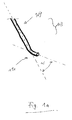
- the curvature may, as in Fig. 1a Consisting of an enlarged portion of the distal end portion 103 Fig. 1 corresponds, shown, about 15 ° to 90 °.
- the distal end of the guide section 107 ends with an opening 113, from which a guide wire guided in the guide section 107 can be guided.
- the proximal end of the catheter 100 has an optional valve 115.
- the valve 115 is like the guide portion 107 also hollow. Its cavity is aligned with that of the guide portion 107, which is why a guide wire can be pushed through both the guide portion and through the valve 115 therethrough.
- Fig. 1a shows the distal end portion 103 of the guide catheter 100 of the invention Fig. 1 in an enlarged view.
- the longitudinal axis of the cavity, which passes through the straight portion 109 is drawn as a dashed line.
- the longitudinal axis of the cavity, which passes through the curved portion 111 is indicated as a dash-dot line.
- Fig. 1a shows that the straight portion 109 and the curved portion 111 are at an angle ⁇ to each other.
- the angle ⁇ gives the curvature, which is assumed here to be attributable exclusively to the shape of the curved portion 111. It is inventively provided both that the curved portion 111 is continuously curved, and that the curved portion 111 in addition to the curvature also has a straight portion or hereby ends at the opening 113.
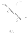
- Fig. 2 shows a hollow needle catheter 200 for use with the guide catheter 100 of the present invention.
- the hollow needle catheter 200 in turn has a hollow guide portion through which a guide wire in the Inside the hollow needle catheter 200 can be introduced and moved relative to this.
- the hollow guide section is at least or finally distributed on a flexible catheter section 201 and a non-flexible hollow needle 203.
- the flexible hollow needle 203 represents the distal end of the hollow needle catheter 200. It can have a slanted cutting edge 205. "Oblique” here means that the circumferential cutting edge of the cutting edge 205 does not circumscribe a round but an oval surface.
- the hollow needle catheter 200 may be dimensioned to be received in the hollow guide portion 107 of the guide catheter 100 and to be able to emerge from the opening 113 of the guide catheter 100 both with its cutting edge 205 of the hollow needle 203 and with the flexible catheter portion 201.
- Fig. 3 shows a positioning catheter 300 according to the invention, in a first embodiment thereof.
- the positioning catheter 300 has a distal end portion 301 and a proximal end portion 303.
- the positioning catheter 300 has at least or exactly two curvature sections 305 and 307 which are arranged in a common first plane (the plane of the drawing in FIG Fig. 3 ) and which are each distal to a straight section 309.
- the positioning catheter 300 may be in addition to the aforementioned curvature, which lies in the first plane, at least or exactly have a curvature in a second plane, wherein the second plane is perpendicular to the first plane.
- the curvature in the second plane may be such that the opening 311 further above or in front of the plane of the drawing Fig. 3 At least two other portions of the positioning catheter 300 that are in the plane of the drawing are at least two.
- the curvature in the second plane may preferably be between -45 ° and + 90 °.
- the distal end portion 301 has an end opening or opening 311 of a guide portion which extends from the opening 311 to a proximal end of the proximal end portion 303, optionally to a valve 313 optionally placed on the proximal end.
- the in Fig. 3 positioning catheter 300 shown in an exemplary embodiment is curved to, when pushed through the interatrial septum 715, project with its opening 311 in front of, or in the region of, the native mitral valve apparatus (s) 719. Its special curvature allows it to be easily guided to the left atrium and the mitral valve 719 when it passes through the brachiocephalic vein 711 or superior vena cava 713. In this case, the positioning catheter 300 can detachably carry the mitral valve implant 600.
- the positioning catheter 300 serves as a guide catheter, through the hollow guide portion through another catheter, referred to herein as Mitralklappen catheter 500 or mitralklappentransmitting catheter 500 which carries the Mitralklappenimplantat 600, to the native mitral valve 719 whose replacement is performed.
- the positioning catheter 300 may be designed to be rigid such that its flexural modulus is stiffer or greater than the flexural modulus of the mitral valve catheter 500 which carries the mitral valve implant 600, such that the positioning catheter 300 will be in use, i. That is, when the mitral valve implant 600 is guided by the guide portion thereof, it does not lose shape.
- the positioning catheter 300 or its guide portion has the same or lower strength or the same or lower flexural modulus than the mitral valve implant 600.
- the above-mentioned curvatures or bends of the positioning catheter are shaped such that the distal opening 311 preferably lies directly above the native mitral valve apparatus 719 or in the mitral valve apparatus 719.
- FIG. 12 shows the distal end portion 301 and the distal portion of the proximal end portion 303 of the positioning catheter 300 of FIG Fig. 3 in a slightly enlarged view.
- the longitudinal axis of the cavity, which passes through the straight portion 309 is drawn as a dashed line.
- the longitudinal axis of the cavity, which passes through the first curved portion 305, is indicated as a dotted line.
- the longitudinal axis of the cavity, which passes through the second curved portion 307, is indicated as a dash-dot line.
- Fig. 3a shows that the straight portion 309 and the second curved portion 307 are at an angle ⁇ to each other.
- the angle ⁇ gives the first curvature, which is assumed here to be attributable exclusively to the shape of the second curved portion 307.
- Fig. 3a shows that the second curved portion 307 and the first curved portion 305 are at an angle ⁇ to each other.
- the angle ⁇ gives the second curvature, which is assumed here to be attributable exclusively to the shape of the first curved portion 305.
- first curved portion 305 is continuously curved, as well as that it also has a straight portion in addition to the curvature or hereby ends at the opening 311.
- the angle ⁇ can be between 0 ° and 120 °, preferably 20 ° to 40 °.
- the angle ⁇ can be between 10 ° and 120 °, preferably between 90 ° and 120 °.
- An angle ⁇ which extends between the longitudinal axis of the cavity which passes through the straight section 309 (see the dotted line) and an exit exit direction from the opening 311, drawn by means of a dashed-circle line, is double in the drawing plane or the plane Curvature advantageous between 0 ° (parallel) and 60 °.
- One between the first curvature 305 and the second curvature 307 (or between the intersection of the straight lines which the Angles ⁇ and ⁇ ) located portion 308 may be about 2 cm to 12 cm, preferably between 2 cm and 6 cm long.
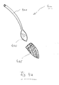
- Fig. 4 shows a hemostasis catheter or balloon catheter 400, which may be part of the kit or catheter system according to the invention.
- the balloon catheter 400 has a conduit section 401 and a balloon section 403 connected thereto and in fluid communication.
- the balloon portion 403 may be filled with fluid, usually saline, via the conduit portion 401 and thereby expanded or expanded.
- the balloon portion 403 has a hemostatic, resorbable sheath 405, which remain in the puncture wound after use of the balloon catheter 400 and can be resorbed there.
- the balloon portion 403 is in Fig. 4 shown expanded.
- Fig. 4a shows the balloon catheter 400 of Fig. 4 in a non or less expanded state, in which it can be removed from the puncture wound after complete or partial deflation of the fluid or fluid pressure prevailing in the balloon interior.
- the optional sheath 405 may remain in the puncture wound after deflation of the balloon or balloon portion 403. It can be absorbed there.
- Fig. 5 and Fig. 5a show an exemplary mitral valve catheter 500 according to the invention, in a first embodiment thereof.
- the mitral valve catheter 500 has a mitral valve implant 600 in a distal end region 501.
- the mitral valve implant 600 is once in the expanded state of the mitral valve prosthesis ( Fig. 5 ), once in less expanded or folded condition ( Fig. 5a ).
- the mitral valve implant 600 is based on a foldable or crimpable stent body, which in Fig. 5 and Fig. 5a and flap sails not shown in these figures.
- the stent body is preferably made of Nitinol or another shape memory material or has such.
- the stent body has three longitudinal connectors or posts 605, which connect an annular distal guide structure 601 and a ring-shaped proximal guide structure 603 to one another.
- strings 617 run, which also run in an inner longitudinal lumen of the mitral valve catheter 500.
- the strings 617 are provided so as to be able to exert a radially inward pressure on the annular distal guide structure 601 and the annular proximal guide structure 603 with the aim of increasing the diameter of these two To be able to reduce guide structures and thus also the diameter of the stent body.
- the features of the mitral valve implant 600 described herein may be provided on the mitral valve catheter 500 or on the positioning catheter 300 (eg, on its distal end portion) such that the mitral valve leaflets flow distally proximally (based on the location of the mitral valve graft 600) on the catheter, in Fig. 5 from the top to the bottom), but in the opposite direction (in Fig. 5 So from bottom to top).
- the mitral valve implant 600 is thus preferably placed on the catheter for implantation in which the catheter is pushed from the left atrium to the native mitral valve 719, not from the left ventricle.
- Fig. 6a to 6f show an inventive embodiment of the method according to the invention on a patient.
- Fig. 6a shows the puncturing required for the implantation of the mitral valve implant 600.
- the angle between the right sternocleidomastoid muscle 701 and the right 703 clavicle is identified.
- the skin will be around 1 cm beside the head of the skin Sternocleidomasteideus 701 and punctured at a distance of about 1 cm from the clavicle 703.
- the needle 705 used for the puncture is introduced at an angle of 35-45 ° to the body axis and at an angle of about 15 ° to the body plane (preferably targeted to the opposite nipple).
- the needle 705 then punctures the "vein angle" of the subclavian vein 707 and the internal jugular vein 709, when united to the brachiocephalic vein 711.
- the interatrial septum with the reference numeral 715, the inferior vena cava with reference numeral 717 and the mitral valve with the reference numeral 719 designates.
- Fig. 6b shows the preparation of the puncture of the interatrial septum 715.
- Fig. 6c shows the state after puncture of the interatrial septum 715, to which the hollow needle catheter 200 has been inserted into the hollow guide portion of the rigid guide catheter 100 according to the invention, and with the emerging from the opening 113 blade 205 of the hollow needle 203, the interatrial septum 715 was punctured.
- Fig. 6c further shows that via the hollow needle catheter 200, a guide wire 800 in the left atrium and through the opening created by means of puncture with the hollow needle 203 in interatrial septum 715 was pushed further into the left ventricle.
- the guide catheter 100 is halfway out of the patient's body.
- Dilation of the opening created by hollow needle 203 in the interatrial septum 715 can be dilated by means of a dilator or balloon.
- the distal end descent of the positioning catheter 300 may be introduced "over the wire” into the brachiocephalic vein and the superior vena cava transseptally into the left atrium.
- Fig. 6d shows this condition.
- Fig. 6d shows that the bend of the positioning catheter 300 allows to position its open end just above or in the native mitral valve apparatus as well.
- the mitral valve prosthesis 600 is advanced along the guide section through the interior of the positioning catheter 300 and anchored in the native mitral valve apparatus 719.
- a mitral valve repair are performed.
- FIG. 12 shows a condition of the patient after implantation of the mitral valve implant 600.
- the patient is advanced via the existing port into a hemostatic balloon catheter 400 into the subcutaneous tissue just prior to the puncture site of the brachiocephalic vein 711. This is done advantageously via a Guide wire, which in Fig. 6e not shown.
- the in Fig. 6e shown state corresponds to the state after insertion of the balloon catheter 400 and after removal of the guide wire, if one has been used.
- the balloon portion 403 is filled in the subcutaneous tissue and thus widened and leads to an immediate hemostasis.
- the hemostatic sheath is preferably absorbable.
Landscapes
- Health & Medical Sciences (AREA)
- Cardiology (AREA)
- Oral & Maxillofacial Surgery (AREA)
- Transplantation (AREA)
- Engineering & Computer Science (AREA)
- Biomedical Technology (AREA)
- Heart & Thoracic Surgery (AREA)
- Vascular Medicine (AREA)
- Life Sciences & Earth Sciences (AREA)
- Animal Behavior & Ethology (AREA)
- General Health & Medical Sciences (AREA)
- Public Health (AREA)
- Veterinary Medicine (AREA)
- Prostheses (AREA)
- Media Introduction/Drainage Providing Device (AREA)
Priority Applications (1)
| Application Number | Priority Date | Filing Date | Title |
|---|---|---|---|
| EP15158051.1A EP2918249B1 (fr) | 2014-03-14 | 2015-03-06 | Système de cathéter supra-claviculaire pour un accès transseptal à l'oreillette gauche et ventricule gauche |
Applications Claiming Priority (4)
| Application Number | Priority Date | Filing Date | Title |
|---|---|---|---|
| EP14160061.9A EP2918245B1 (fr) | 2014-03-14 | 2014-03-14 | Valve cardiaque comprenant une pièce de sommet interconnectée avec des feuillets, revers supérieur et manchon inférieur et implant médical |
| EP14160065.0A EP2918246B1 (fr) | 2014-03-14 | 2014-03-14 | Ensemble valve cardiaque comprenant une double étanchéité |
| PCT/EP2014/066537 WO2015014960A1 (fr) | 2013-07-31 | 2014-07-31 | Ensemble comprenant un cathéter et un implant supportant une valve |
| EP15158051.1A EP2918249B1 (fr) | 2014-03-14 | 2015-03-06 | Système de cathéter supra-claviculaire pour un accès transseptal à l'oreillette gauche et ventricule gauche |
Publications (3)
| Publication Number | Publication Date |
|---|---|
| EP2918249A2 true EP2918249A2 (fr) | 2015-09-16 |
| EP2918249A3 EP2918249A3 (fr) | 2016-01-13 |
| EP2918249B1 EP2918249B1 (fr) | 2020-04-29 |
Family
ID=52596877
Family Applications (1)
| Application Number | Title | Priority Date | Filing Date |
|---|---|---|---|
| EP15158051.1A Revoked EP2918249B1 (fr) | 2014-03-14 | 2015-03-06 | Système de cathéter supra-claviculaire pour un accès transseptal à l'oreillette gauche et ventricule gauche |
Country Status (1)
| Country | Link |
|---|---|
| EP (1) | EP2918249B1 (fr) |
Cited By (22)
| Publication number | Priority date | Publication date | Assignee | Title |
|---|---|---|---|---|
| US12138160B2 (en) | 2014-11-26 | 2024-11-12 | Edwards Lifesciences Corporation | Transcatheter prosthetic heart valve and delivery system |
| US12285330B2 (en) | 2013-03-14 | 2025-04-29 | Edwards Lifesciences Cardiaq Llc | Prosthesis for atraumatically grasping intralumenal tissue and methods of delivery |
| US12295584B2 (en) | 2015-03-20 | 2025-05-13 | Edwards Lifesciences Corporation | Systems and methods for delivering an implantable device |
| US12295839B2 (en) | 2019-04-23 | 2025-05-13 | Edwards Lifesciences Corporation | Motorized implant delivery system |
| US12303385B2 (en) | 2013-02-04 | 2025-05-20 | Edwards Lifesciences Corporation | Method of implanting a spacer body in a mitral valve |
| US12310853B2 (en) | 2014-09-28 | 2025-05-27 | Edwards Lifesciences Corporation | Systems and methods for treating cardiac dysfunction |
| US12318290B2 (en) | 2010-09-23 | 2025-06-03 | Edwards Lifesciences Cardiaq Llc | Replacement heart valves, delivery devices and methods |
| US12343252B2 (en) | 2009-04-15 | 2025-07-01 | Edwards Lifesciences Cardiaq Llc | Vascular implant and delivery system |
| US12364587B2 (en) | 2020-12-18 | 2025-07-22 | Edwards Lifesciences Corporation | Storage jar assembly for a prosthetic heart valve |
| US12376961B2 (en) | 2008-05-01 | 2025-08-05 | Edwards Lifesciences Corporation | Method of implanting a prosthetic heart valve assembly |
| US12403004B2 (en) | 2014-06-06 | 2025-09-02 | Edwards Lifesciences Corporation | Method for replacing a tricuspid valve |
| US12409031B2 (en) | 2009-12-04 | 2025-09-09 | Edwards Lifesciences Corporation | Prosthetic valve having a multi-part frame |
| US12427016B2 (en) | 2009-04-29 | 2025-09-30 | Edwards Lifesciences Corporation | Apparatus and method for replacing a diseased cardiac valve |
| US12440335B2 (en) | 2018-01-25 | 2025-10-14 | Edwards Lifesciences Corporation | Delivery system for aided replacement valve recapture and repositioning post-deployment |
| US12447011B2 (en) | 2016-07-21 | 2025-10-21 | Edwards Lifesciences Corporation | Replacement heart valve prosthesis |
| US12447014B2 (en) | 2019-04-12 | 2025-10-21 | Edwards Lifesciences Corporation | Valve with multi-part frame and associated resilient bridging features |
| US12502276B2 (en) | 2011-05-16 | 2025-12-23 | Edwards Lifesciences Corporation | Inversion delivery device and method for a prosthesis |
| US12533233B2 (en) | 2021-10-27 | 2026-01-27 | Edwards Lifesciences Corporation | System and method for crimping and loading a prosthetic heart valve |
| US12551207B2 (en) | 2008-11-21 | 2026-02-17 | Percutaneous Cardiovascular Solutions Pty Ltd | Heart valve prosthesis and method |
| US12558218B2 (en) | 2017-07-06 | 2026-02-24 | Edwards Lifesciences Corporation | Steerable delivery system and components |
| US12599480B2 (en) | 2015-04-21 | 2026-04-14 | Edwards Lifesciences Corporation | Percutaneous mitral valve replacement device |
| US12611298B2 (en) | 2016-08-26 | 2026-04-28 | Edwards Lifesciences Corporation | Multi-portion replacement heart valve prosthesis |
Families Citing this family (18)
| Publication number | Priority date | Publication date | Assignee | Title |
|---|---|---|---|---|
| JP2008513060A (ja) | 2004-09-14 | 2008-05-01 | エドワーズ ライフサイエンシーズ アーゲー | 心臓弁逆流の処置のためのデバイスおよび方法 |
| US8579964B2 (en) | 2010-05-05 | 2013-11-12 | Neovasc Inc. | Transcatheter mitral valve prosthesis |
| US9308087B2 (en) | 2011-04-28 | 2016-04-12 | Neovasc Tiara Inc. | Sequentially deployed transcatheter mitral valve prosthesis |
| US9554897B2 (en) | 2011-04-28 | 2017-01-31 | Neovasc Tiara Inc. | Methods and apparatus for engaging a valve prosthesis with tissue |
| US9345573B2 (en) | 2012-05-30 | 2016-05-24 | Neovasc Tiara Inc. | Methods and apparatus for loading a prosthesis onto a delivery system |
| US9572665B2 (en) | 2013-04-04 | 2017-02-21 | Neovasc Tiara Inc. | Methods and apparatus for delivering a prosthetic valve to a beating heart |
| WO2015127283A1 (fr) | 2014-02-21 | 2015-08-27 | Cardiaq Valve Technologies, Inc. | Dispositif d'acheminement pour le déploiement maîtrisé d'une de valvule de substitution |
| WO2017100927A1 (fr) | 2015-12-15 | 2017-06-22 | Neovasc Tiara Inc. | Système d'administration trans-septale |
| JP7006940B2 (ja) | 2016-01-29 | 2022-01-24 | ニオバスク ティアラ インコーポレイテッド | 流出の閉塞を回避するための人工弁 |
| WO2018090148A1 (fr) | 2016-11-21 | 2018-05-24 | Neovasc Tiara Inc. | Procédés et systèmes de rétraction rapide d'un système de pose de valvule cardiaque transcathéter |
| CN111263622A (zh) | 2017-08-25 | 2020-06-09 | 内奥瓦斯克迪亚拉公司 | 顺序展开的经导管二尖瓣假体 |
| AU2019374743B2 (en) | 2018-11-08 | 2022-03-03 | Neovasc Tiara Inc. | Ventricular deployment of a transcatheter mitral valve prosthesis |
| EP3921012A1 (fr) | 2019-02-04 | 2021-12-15 | Edwards Lifesciences Corporation | Appareil à fil de guidage et méthodes |
| JP7430732B2 (ja) | 2019-03-08 | 2024-02-13 | ニオバスク ティアラ インコーポレイテッド | 回収可能補綴物送達システム |
| EP3946163B1 (fr) | 2019-04-01 | 2025-08-20 | Neovasc Tiara Inc. | Valve prothétique déployable de manière contrôlable |
| US11491006B2 (en) | 2019-04-10 | 2022-11-08 | Neovasc Tiara Inc. | Prosthetic valve with natural blood flow |
| EP4729110A2 (fr) | 2019-05-20 | 2026-04-22 | Neovasc Tiara Inc. | Introducteur avec mécanisme d'hémostase |
| WO2020257643A1 (fr) | 2019-06-20 | 2020-12-24 | Neovasc Tiara Inc. | Valve mitrale prothétique à profil bas |
Citations (2)
| Publication number | Priority date | Publication date | Assignee | Title |
|---|---|---|---|---|
| WO2009109348A1 (fr) | 2008-03-02 | 2009-09-11 | Transcatheter Technologies Gmbh | Stent qui est apte à être réduit en diamètre de façon répétée contrôlée à partir de l'état expansé |
| WO2015014960A1 (fr) | 2013-07-31 | 2015-02-05 | Transcatheter Technologies Gmbh | Ensemble comprenant un cathéter et un implant supportant une valve |
Family Cites Families (48)
| Publication number | Priority date | Publication date | Assignee | Title |
|---|---|---|---|---|
| US4919133A (en) | 1988-08-18 | 1990-04-24 | Chiang Tien Hon | Catheter apparatus employing shape memory alloy structures |
| US5795325A (en) * | 1991-07-16 | 1998-08-18 | Heartport, Inc. | Methods and apparatus for anchoring an occluding member |
| US6866650B2 (en) | 1991-07-16 | 2005-03-15 | Heartport, Inc. | System for cardiac procedures |
| US5695457A (en) * | 1994-07-28 | 1997-12-09 | Heartport, Inc. | Cardioplegia catheter system |
| JPH09173343A (ja) | 1995-12-21 | 1997-07-08 | Daig Corp | 心房性不整脈の非外科的マッピングおよび治療用の形状付与された誘導導入器 |
| US7090683B2 (en) | 1998-02-24 | 2006-08-15 | Hansen Medical, Inc. | Flexible instrument |
| US7226467B2 (en) | 1999-04-09 | 2007-06-05 | Evalve, Inc. | Fixation device delivery catheter, systems and methods of use |
| CA2620783C (fr) | 1999-04-09 | 2011-04-05 | Evalve, Inc. | Procede et dispositif de reparation de valvule cardiaque |
| US20040044350A1 (en) | 1999-04-09 | 2004-03-04 | Evalve, Inc. | Steerable access sheath and methods of use |
| US6375668B1 (en) | 1999-06-02 | 2002-04-23 | Hanson S. Gifford | Devices and methods for treating vascular malformations |
| US6312447B1 (en) | 1999-10-13 | 2001-11-06 | The General Hospital Corporation | Devices and methods for percutaneous mitral valve repair |
| US6520939B2 (en) | 2001-02-13 | 2003-02-18 | Scimed Life Systems, Inc. | Hemostasis valve |
| FR2828091B1 (fr) | 2001-07-31 | 2003-11-21 | Seguin Jacques | Ensemble permettant la mise en place d'une valve prothetique dans un conduit corporel |
| US20090112303A1 (en) | 2001-11-28 | 2009-04-30 | Lee Bolduc | Devices, systems, and methods for endovascular staple and/or prosthesis delivery and implantation |
| US7462184B2 (en) | 2002-05-06 | 2008-12-09 | Pressure Products Medical Supplies Inc. | Introducer for accessing the coronary sinus of a heart |
| US20040068161A1 (en) | 2002-10-02 | 2004-04-08 | Couvillon Lucien Alfred | Thrombolysis catheter |
| US6960207B2 (en) | 2003-01-21 | 2005-11-01 | St Jude Medical, Daig Division, Inc. | Ablation catheter having a virtual electrode comprising portholes and a porous conductor |
| US20040260394A1 (en) | 2003-06-20 | 2004-12-23 | Medtronic Vascular, Inc. | Cardiac valve annulus compressor system |
| ATE442107T1 (de) | 2003-07-21 | 2009-09-15 | Univ Pennsylvania | Perkutane herzklappe |
| US7402151B2 (en) | 2004-12-17 | 2008-07-22 | Biocardia, Inc. | Steerable guide catheters and methods for their use |
| WO2006122061A1 (fr) | 2005-05-06 | 2006-11-16 | Acumen Medical, Inc. | Catheters orientables a forme complexe et procedes de fabrication desdits catheters |
| US7892186B2 (en) | 2005-12-09 | 2011-02-22 | Heraeus Materials S.A. | Handle and articulator system and method |
| CN101384293B (zh) | 2006-03-06 | 2013-04-24 | 泰尔茂株式会社 | 导丝 |
| US20070225681A1 (en) | 2006-03-21 | 2007-09-27 | Medtronic Vascular | Catheter Having a Selectively Formable Distal Section |
| JP2007330548A (ja) | 2006-06-15 | 2007-12-27 | Asahi Intecc Co Ltd | 診断治療用ガイドカテーテル |
| US8105375B2 (en) | 2007-01-19 | 2012-01-31 | The Cleveland Clinic Foundation | Method for implanting a cardiovascular valve |
| US10166066B2 (en) | 2007-03-13 | 2019-01-01 | University Of Virginia Patent Foundation | Epicardial ablation catheter and method of use |
| EP2148608A4 (fr) | 2007-04-27 | 2010-04-28 | Voyage Medical Inc | Cathéter pour la visualisation et la manipulation de tissus man uvrables de formes complexes |
| US20120191181A1 (en) | 2007-04-27 | 2012-07-26 | Kassab Ghassan S | Systems and methods for localization of a puncture site relative to a mammalian tissue of interest |
| US8096985B2 (en) | 2008-05-07 | 2012-01-17 | Guided Delivery Systems Inc. | Deflectable guide |
| US8591460B2 (en) | 2008-06-13 | 2013-11-26 | Cardiosolutions, Inc. | Steerable catheter and dilator and system and method for implanting a heart implant |
| EP2135638B1 (fr) | 2008-06-20 | 2015-03-11 | Ela Medical | Mandrin préformé de guidage d'une sonde en contact avec la paroi du septum |
| DE102010008360A1 (de) | 2010-02-17 | 2011-09-29 | Transcatheter Technologies Gmbh | Medizinisches Implantat, in welchem beim Crimpen bzw. Falten Lücken verbleiben, Verfahren und Einrichtung zum Verbringen |
| EP3335670B1 (fr) * | 2010-03-05 | 2022-05-04 | Edwards Lifesciences Corporation | Mécanismes de retenue pour valvules prothétiques |
| WO2011143359A2 (fr) | 2010-05-11 | 2011-11-17 | Cardiac Inventions Unlimited | Appareil pour exécution sans danger de technique transseptale et mise en place et positionnement de cathéter d'ablation |
| US9072872B2 (en) | 2010-10-29 | 2015-07-07 | Medtronic, Inc. | Telescoping catheter delivery system for left heart endocardial device placement |
| EP3351215B1 (fr) * | 2011-01-18 | 2024-09-11 | Loma Vista Medical, Inc. | Dispositifs médicaux gonflables |
| US8845717B2 (en) | 2011-01-28 | 2014-09-30 | Middle Park Medical, Inc. | Coaptation enhancement implant, system, and method |
| JP2012213478A (ja) | 2011-03-31 | 2012-11-08 | Sumitomo Bakelite Co Ltd | 医療用機器 |
| US8845588B2 (en) | 2011-04-19 | 2014-09-30 | Medtronic Vascular, Inc. | Sheath introducer system with exchangeable hemostatic valves |
| CN107496054B (zh) | 2011-06-21 | 2020-03-03 | 托尔福公司 | 人工心脏瓣膜装置及相关系统和方法 |
| JP6151705B2 (ja) * | 2011-10-19 | 2017-06-21 | トゥエルヴ, インコーポレイテッド | 心臓弁置換のためのデバイス、システムおよび方法 |
| US9039757B2 (en) | 2011-10-19 | 2015-05-26 | Twelve, Inc. | Prosthetic heart valve devices, prosthetic mitral valves and associated systems and methods |
| CA3208176A1 (fr) | 2012-01-31 | 2013-08-08 | Mitral Valve Technologies Sarl | Dispositifs, systemes et procedes de fixation de valvule mitrale |
| US9180008B2 (en) | 2012-02-29 | 2015-11-10 | Valcare, Inc. | Methods, devices, and systems for percutaneously anchoring annuloplasty rings |
| US9579198B2 (en) | 2012-03-01 | 2017-02-28 | Twelve, Inc. | Hydraulic delivery systems for prosthetic heart valve devices and associated methods |
| US10004877B2 (en) | 2012-05-07 | 2018-06-26 | St. Jude Medical, Atrial Fibrillation Division, Inc. | Deflectable catheter shaft section, catheter incorporating same, and method of manufacturing same |
| CN105263442B (zh) | 2013-02-04 | 2019-02-15 | 托尔福公司 | 用于人工心脏瓣膜装置的液压输送系统及相关方法 |
-
2015
- 2015-03-06 EP EP15158051.1A patent/EP2918249B1/fr not_active Revoked
Patent Citations (2)
| Publication number | Priority date | Publication date | Assignee | Title |
|---|---|---|---|---|
| WO2009109348A1 (fr) | 2008-03-02 | 2009-09-11 | Transcatheter Technologies Gmbh | Stent qui est apte à être réduit en diamètre de façon répétée contrôlée à partir de l'état expansé |
| WO2015014960A1 (fr) | 2013-07-31 | 2015-02-05 | Transcatheter Technologies Gmbh | Ensemble comprenant un cathéter et un implant supportant une valve |
Cited By (25)
| Publication number | Priority date | Publication date | Assignee | Title |
|---|---|---|---|---|
| US12376961B2 (en) | 2008-05-01 | 2025-08-05 | Edwards Lifesciences Corporation | Method of implanting a prosthetic heart valve assembly |
| US12551207B2 (en) | 2008-11-21 | 2026-02-17 | Percutaneous Cardiovascular Solutions Pty Ltd | Heart valve prosthesis and method |
| US12343252B2 (en) | 2009-04-15 | 2025-07-01 | Edwards Lifesciences Cardiaq Llc | Vascular implant and delivery system |
| US12447013B2 (en) | 2009-04-29 | 2025-10-21 | The Cleveland Clinic Foundation | Apparatus and method for replacing a diseased cardiac valve |
| US12427016B2 (en) | 2009-04-29 | 2025-09-30 | Edwards Lifesciences Corporation | Apparatus and method for replacing a diseased cardiac valve |
| US12433743B2 (en) | 2009-12-04 | 2025-10-07 | Edwards Lifesciences Corporation | System for replacing a native valve of the heart |
| US12409031B2 (en) | 2009-12-04 | 2025-09-09 | Edwards Lifesciences Corporation | Prosthetic valve having a multi-part frame |
| US12318290B2 (en) | 2010-09-23 | 2025-06-03 | Edwards Lifesciences Cardiaq Llc | Replacement heart valves, delivery devices and methods |
| US12502276B2 (en) | 2011-05-16 | 2025-12-23 | Edwards Lifesciences Corporation | Inversion delivery device and method for a prosthesis |
| US12303385B2 (en) | 2013-02-04 | 2025-05-20 | Edwards Lifesciences Corporation | Method of implanting a spacer body in a mitral valve |
| US12357453B2 (en) | 2013-02-04 | 2025-07-15 | Edwards Lifesciences Corporation | Prosthetic heart valve with atrial sealing member |
| US12285330B2 (en) | 2013-03-14 | 2025-04-29 | Edwards Lifesciences Cardiaq Llc | Prosthesis for atraumatically grasping intralumenal tissue and methods of delivery |
| US12403004B2 (en) | 2014-06-06 | 2025-09-02 | Edwards Lifesciences Corporation | Method for replacing a tricuspid valve |
| US12310853B2 (en) | 2014-09-28 | 2025-05-27 | Edwards Lifesciences Corporation | Systems and methods for treating cardiac dysfunction |
| US12138160B2 (en) | 2014-11-26 | 2024-11-12 | Edwards Lifesciences Corporation | Transcatheter prosthetic heart valve and delivery system |
| US12295584B2 (en) | 2015-03-20 | 2025-05-13 | Edwards Lifesciences Corporation | Systems and methods for delivering an implantable device |
| US12599480B2 (en) | 2015-04-21 | 2026-04-14 | Edwards Lifesciences Corporation | Percutaneous mitral valve replacement device |
| US12447011B2 (en) | 2016-07-21 | 2025-10-21 | Edwards Lifesciences Corporation | Replacement heart valve prosthesis |
| US12611298B2 (en) | 2016-08-26 | 2026-04-28 | Edwards Lifesciences Corporation | Multi-portion replacement heart valve prosthesis |
| US12558218B2 (en) | 2017-07-06 | 2026-02-24 | Edwards Lifesciences Corporation | Steerable delivery system and components |
| US12440335B2 (en) | 2018-01-25 | 2025-10-14 | Edwards Lifesciences Corporation | Delivery system for aided replacement valve recapture and repositioning post-deployment |
| US12447014B2 (en) | 2019-04-12 | 2025-10-21 | Edwards Lifesciences Corporation | Valve with multi-part frame and associated resilient bridging features |
| US12295839B2 (en) | 2019-04-23 | 2025-05-13 | Edwards Lifesciences Corporation | Motorized implant delivery system |
| US12364587B2 (en) | 2020-12-18 | 2025-07-22 | Edwards Lifesciences Corporation | Storage jar assembly for a prosthetic heart valve |
| US12533233B2 (en) | 2021-10-27 | 2026-01-27 | Edwards Lifesciences Corporation | System and method for crimping and loading a prosthetic heart valve |
Also Published As
| Publication number | Publication date |
|---|---|
| EP2918249B1 (fr) | 2020-04-29 |
| EP2918249A3 (fr) | 2016-01-13 |
Similar Documents
| Publication | Publication Date | Title |
|---|---|---|
| EP2918249B1 (fr) | Système de cathéter supra-claviculaire pour un accès transseptal à l'oreillette gauche et ventricule gauche | |
| EP1942834B1 (fr) | Instrument médical auto-extensible pour le traitement de défaillances cardiaques chez un patient | |
| EP1940321B1 (fr) | Dispositif pour implanter et fixer des valvules prothetiques | |
| DE60116786T2 (de) | Minimalinvasives system mit schablone für ein annuloplastisches reparatursegment | |
| DE60119944T2 (de) | Endovaskulare splintvorrichtungen | |
| DE69921817T2 (de) | Aus mehreren seiten bestehende intrluminale medizinische vorrichtung | |
| DE60128705T2 (de) | Vorrichtung zur verminderung von erhöhtem lungenvenendruck | |
| DE10049814B4 (de) | Vorrichtung zur Unterstützung chirurgischer Maßnahmen innerhalb eines Gefäßes, insbesondere zur minimalinvasiven Explantation und Implantation von Herzklappen | |
| DE69932943T2 (de) | Eine endoluminalen, abzweigenden gefässprothese | |
| DE69734244T2 (de) | Vorrichtung zum einbringen eines medizinischen transplantates | |
| DE10065824B4 (de) | Endovaskulärer Stent zur Implantation in den aufsteigenden Ast der Aorta | |
| CH684307A5 (de) | Verlängerung von linearem und rohrförmigem Gewebe. | |
| DE102017126715A1 (de) | Implantat zur Behandlung einer biologischen Klappe | |
| DE19933522A1 (de) | Chirurgisches Verfahren und Vorrichtung zum Erhöhen der Herzleistung | |
| DE202008018557U1 (de) | Eine Ersatzklappe | |
| DE102015107242A1 (de) | Implantat | |
| EP2395944A1 (fr) | Cathéter | |
| EP2149390A2 (fr) | Ligne de cathéter ou d'électrodes implantable | |
| DE202007005491U1 (de) | Medizinische Vorrichtung zur Behandlung einer Aortenklappeninsuffizienz | |
| EP4215128B1 (fr) | Dispositif d'occlusion, système de dispositif d'occlusion et cathéter d'introduction et procédé de fourniture du système | |
| EP3678589B1 (fr) | Système de prothèse vasculaire intraluminal | |
| US20230218395A1 (en) | Compressible shunt implant | |
| AT516899A1 (de) | Kanülenanordnung | |
| EP3852836A1 (fr) | Dispositif canule modulaire | |
| DE69824949T2 (de) | Medizinische Einheit zur Behandlung eines Gefässes mit zugehörigem Dichtungsring |
Legal Events
| Date | Code | Title | Description |
|---|---|---|---|
| PUAI | Public reference made under article 153(3) epc to a published international application that has entered the european phase |
Free format text: ORIGINAL CODE: 0009012 |
|
| AK | Designated contracting states |
Kind code of ref document: A2 Designated state(s): AL AT BE BG CH CY CZ DE DK EE ES FI FR GB GR HR HU IE IS IT LI LT LU LV MC MK MT NL NO PL PT RO RS SE SI SK SM TR |
|
| AX | Request for extension of the european patent |
Extension state: BA ME |
|
| PUAL | Search report despatched |
Free format text: ORIGINAL CODE: 0009013 |
|
| AK | Designated contracting states |
Kind code of ref document: A3 Designated state(s): AL AT BE BG CH CY CZ DE DK EE ES FI FR GB GR HR HU IE IS IT LI LT LU LV MC MK MT NL NO PL PT RO RS SE SI SK SM TR |
|
| AX | Request for extension of the european patent |
Extension state: BA ME |
|
| RIC1 | Information provided on ipc code assigned before grant |
Ipc: A61F 2/24 20060101AFI20151204BHEP |
|
| 17P | Request for examination filed |
Effective date: 20160713 |
|
| RBV | Designated contracting states (corrected) |
Designated state(s): AL AT BE BG CH CY CZ DE DK EE ES FI FR GB GR HR HU IE IS IT LI LT LU LV MC MK MT NL NO PL PT RO RS SE SI SK SM TR |
|
| R17P | Request for examination filed (corrected) |
Effective date: 20160713 |
|
| RAP1 | Party data changed (applicant data changed or rights of an application transferred) |
Owner name: VENUS MEDTECH (HANGZHOU), INC. |
|
| 17Q | First examination report despatched |
Effective date: 20160901 |
|
| STAA | Information on the status of an ep patent application or granted ep patent |
Free format text: STATUS: EXAMINATION IS IN PROGRESS |
|
| GRAP | Despatch of communication of intention to grant a patent |
Free format text: ORIGINAL CODE: EPIDOSNIGR1 |
|
| STAA | Information on the status of an ep patent application or granted ep patent |
Free format text: STATUS: GRANT OF PATENT IS INTENDED |
|
| INTG | Intention to grant announced |
Effective date: 20191129 |
|
| GRAS | Grant fee paid |
Free format text: ORIGINAL CODE: EPIDOSNIGR3 |
|
| GRAA | (expected) grant |
Free format text: ORIGINAL CODE: 0009210 |
|
| STAA | Information on the status of an ep patent application or granted ep patent |
Free format text: STATUS: THE PATENT HAS BEEN GRANTED |
|
| AK | Designated contracting states |
Kind code of ref document: B1 Designated state(s): AL AT BE BG CH CY CZ DE DK EE ES FI FR GB GR HR HU IE IS IT LI LT LU LV MC MK MT NL NO PL PT RO RS SE SI SK SM TR |
|
| REG | Reference to a national code |
Ref country code: GB Ref legal event code: FG4D Free format text: NOT ENGLISH |
|
| REG | Reference to a national code |
Ref country code: CH Ref legal event code: EP |
|
| REG | Reference to a national code |
Ref country code: AT Ref legal event code: REF Ref document number: 1262200 Country of ref document: AT Kind code of ref document: T Effective date: 20200515 |
|
| REG | Reference to a national code |
Ref country code: DE Ref legal event code: R096 Ref document number: 502015012395 Country of ref document: DE |
|
| REG | Reference to a national code |
Ref country code: IE Ref legal event code: FG4D Free format text: LANGUAGE OF EP DOCUMENT: GERMAN |
|
| REG | Reference to a national code |
Ref country code: CH Ref legal event code: NV Representative=s name: SERVOPATENT GMBH, CH |
|
| REG | Reference to a national code |
Ref country code: NL Ref legal event code: FP |
|
| REG | Reference to a national code |
Ref country code: LT Ref legal event code: MG4D |
|
| PG25 | Lapsed in a contracting state [announced via postgrant information from national office to epo] |
Ref country code: FI Free format text: LAPSE BECAUSE OF FAILURE TO SUBMIT A TRANSLATION OF THE DESCRIPTION OR TO PAY THE FEE WITHIN THE PRESCRIBED TIME-LIMIT Effective date: 20200429 Ref country code: NO Free format text: LAPSE BECAUSE OF FAILURE TO SUBMIT A TRANSLATION OF THE DESCRIPTION OR TO PAY THE FEE WITHIN THE PRESCRIBED TIME-LIMIT Effective date: 20200729 Ref country code: SE Free format text: LAPSE BECAUSE OF FAILURE TO SUBMIT A TRANSLATION OF THE DESCRIPTION OR TO PAY THE FEE WITHIN THE PRESCRIBED TIME-LIMIT Effective date: 20200429 Ref country code: LT Free format text: LAPSE BECAUSE OF FAILURE TO SUBMIT A TRANSLATION OF THE DESCRIPTION OR TO PAY THE FEE WITHIN THE PRESCRIBED TIME-LIMIT Effective date: 20200429 Ref country code: GR Free format text: LAPSE BECAUSE OF FAILURE TO SUBMIT A TRANSLATION OF THE DESCRIPTION OR TO PAY THE FEE WITHIN THE PRESCRIBED TIME-LIMIT Effective date: 20200730 Ref country code: PT Free format text: LAPSE BECAUSE OF FAILURE TO SUBMIT A TRANSLATION OF THE DESCRIPTION OR TO PAY THE FEE WITHIN THE PRESCRIBED TIME-LIMIT Effective date: 20200831 Ref country code: IS Free format text: LAPSE BECAUSE OF FAILURE TO SUBMIT A TRANSLATION OF THE DESCRIPTION OR TO PAY THE FEE WITHIN THE PRESCRIBED TIME-LIMIT Effective date: 20200829 |
|
| PG25 | Lapsed in a contracting state [announced via postgrant information from national office to epo] |
Ref country code: RS Free format text: LAPSE BECAUSE OF FAILURE TO SUBMIT A TRANSLATION OF THE DESCRIPTION OR TO PAY THE FEE WITHIN THE PRESCRIBED TIME-LIMIT Effective date: 20200429 Ref country code: HR Free format text: LAPSE BECAUSE OF FAILURE TO SUBMIT A TRANSLATION OF THE DESCRIPTION OR TO PAY THE FEE WITHIN THE PRESCRIBED TIME-LIMIT Effective date: 20200429 Ref country code: LV Free format text: LAPSE BECAUSE OF FAILURE TO SUBMIT A TRANSLATION OF THE DESCRIPTION OR TO PAY THE FEE WITHIN THE PRESCRIBED TIME-LIMIT Effective date: 20200429 Ref country code: BG Free format text: LAPSE BECAUSE OF FAILURE TO SUBMIT A TRANSLATION OF THE DESCRIPTION OR TO PAY THE FEE WITHIN THE PRESCRIBED TIME-LIMIT Effective date: 20200729 |
|
| PG25 | Lapsed in a contracting state [announced via postgrant information from national office to epo] |
Ref country code: AL Free format text: LAPSE BECAUSE OF FAILURE TO SUBMIT A TRANSLATION OF THE DESCRIPTION OR TO PAY THE FEE WITHIN THE PRESCRIBED TIME-LIMIT Effective date: 20200429 |
|
| REG | Reference to a national code |
Ref country code: DE Ref legal event code: R026 Ref document number: 502015012395 Country of ref document: DE |
|
| PG25 | Lapsed in a contracting state [announced via postgrant information from national office to epo] |
Ref country code: SM Free format text: LAPSE BECAUSE OF FAILURE TO SUBMIT A TRANSLATION OF THE DESCRIPTION OR TO PAY THE FEE WITHIN THE PRESCRIBED TIME-LIMIT Effective date: 20200429 Ref country code: RO Free format text: LAPSE BECAUSE OF FAILURE TO SUBMIT A TRANSLATION OF THE DESCRIPTION OR TO PAY THE FEE WITHIN THE PRESCRIBED TIME-LIMIT Effective date: 20200429 Ref country code: IT Free format text: LAPSE BECAUSE OF FAILURE TO SUBMIT A TRANSLATION OF THE DESCRIPTION OR TO PAY THE FEE WITHIN THE PRESCRIBED TIME-LIMIT Effective date: 20200429 Ref country code: CZ Free format text: LAPSE BECAUSE OF FAILURE TO SUBMIT A TRANSLATION OF THE DESCRIPTION OR TO PAY THE FEE WITHIN THE PRESCRIBED TIME-LIMIT Effective date: 20200429 Ref country code: ES Free format text: LAPSE BECAUSE OF FAILURE TO SUBMIT A TRANSLATION OF THE DESCRIPTION OR TO PAY THE FEE WITHIN THE PRESCRIBED TIME-LIMIT Effective date: 20200429 Ref country code: EE Free format text: LAPSE BECAUSE OF FAILURE TO SUBMIT A TRANSLATION OF THE DESCRIPTION OR TO PAY THE FEE WITHIN THE PRESCRIBED TIME-LIMIT Effective date: 20200429 Ref country code: DK Free format text: LAPSE BECAUSE OF FAILURE TO SUBMIT A TRANSLATION OF THE DESCRIPTION OR TO PAY THE FEE WITHIN THE PRESCRIBED TIME-LIMIT Effective date: 20200429 |
|
| PLBI | Opposition filed |
Free format text: ORIGINAL CODE: 0009260 |
|
| PLBI | Opposition filed |
Free format text: ORIGINAL CODE: 0009260 |
|
| PLAX | Notice of opposition and request to file observation + time limit sent |
Free format text: ORIGINAL CODE: EPIDOSNOBS2 |
|
| PG25 | Lapsed in a contracting state [announced via postgrant information from national office to epo] |
Ref country code: PL Free format text: LAPSE BECAUSE OF FAILURE TO SUBMIT A TRANSLATION OF THE DESCRIPTION OR TO PAY THE FEE WITHIN THE PRESCRIBED TIME-LIMIT Effective date: 20200429 Ref country code: SK Free format text: LAPSE BECAUSE OF FAILURE TO SUBMIT A TRANSLATION OF THE DESCRIPTION OR TO PAY THE FEE WITHIN THE PRESCRIBED TIME-LIMIT Effective date: 20200429 |
|
| 26 | Opposition filed |
Opponent name: MEDTRONIC INC. Effective date: 20210127 |
|
| 26 | Opposition filed |
Opponent name: EDWARDS LIFESCIENCES CORPORATION Effective date: 20210129 |
|
| PG25 | Lapsed in a contracting state [announced via postgrant information from national office to epo] |
Ref country code: SI Free format text: LAPSE BECAUSE OF FAILURE TO SUBMIT A TRANSLATION OF THE DESCRIPTION OR TO PAY THE FEE WITHIN THE PRESCRIBED TIME-LIMIT Effective date: 20200429 |
|
| PLBB | Reply of patent proprietor to notice(s) of opposition received |
Free format text: ORIGINAL CODE: EPIDOSNOBS3 |
|
| PG25 | Lapsed in a contracting state [announced via postgrant information from national office to epo] |
Ref country code: MC Free format text: LAPSE BECAUSE OF FAILURE TO SUBMIT A TRANSLATION OF THE DESCRIPTION OR TO PAY THE FEE WITHIN THE PRESCRIBED TIME-LIMIT Effective date: 20200429 |
|
| REG | Reference to a national code |
Ref country code: BE Ref legal event code: MM Effective date: 20210331 |
|
| PG25 | Lapsed in a contracting state [announced via postgrant information from national office to epo] |
Ref country code: LU Free format text: LAPSE BECAUSE OF NON-PAYMENT OF DUE FEES Effective date: 20210306 Ref country code: IE Free format text: LAPSE BECAUSE OF NON-PAYMENT OF DUE FEES Effective date: 20210306 |
|
| REG | Reference to a national code |
Ref country code: AT Ref legal event code: MM01 Ref document number: 1262200 Country of ref document: AT Kind code of ref document: T Effective date: 20210306 |
|
| PG25 | Lapsed in a contracting state [announced via postgrant information from national office to epo] |
Ref country code: BE Free format text: LAPSE BECAUSE OF NON-PAYMENT OF DUE FEES Effective date: 20210331 |
|
| PG25 | Lapsed in a contracting state [announced via postgrant information from national office to epo] |
Ref country code: AT Free format text: LAPSE BECAUSE OF NON-PAYMENT OF DUE FEES Effective date: 20210306 |
|
| RDAF | Communication despatched that patent is revoked |
Free format text: ORIGINAL CODE: EPIDOSNREV1 |
|
| APBM | Appeal reference recorded |
Free format text: ORIGINAL CODE: EPIDOSNREFNO |
|
| APBP | Date of receipt of notice of appeal recorded |
Free format text: ORIGINAL CODE: EPIDOSNNOA2O |
|
| APAH | Appeal reference modified |
Free format text: ORIGINAL CODE: EPIDOSCREFNO |
|
| RAP4 | Party data changed (patent owner data changed or rights of a patent transferred) |
Owner name: VENUS MEDTECH (HANGZHOU), INC. |
|
| APBQ | Date of receipt of statement of grounds of appeal recorded |
Free format text: ORIGINAL CODE: EPIDOSNNOA3O |
|
| PG25 | Lapsed in a contracting state [announced via postgrant information from national office to epo] |
Ref country code: HU Free format text: LAPSE BECAUSE OF FAILURE TO SUBMIT A TRANSLATION OF THE DESCRIPTION OR TO PAY THE FEE WITHIN THE PRESCRIBED TIME-LIMIT; INVALID AB INITIO Effective date: 20150306 |
|
| PG25 | Lapsed in a contracting state [announced via postgrant information from national office to epo] |
Ref country code: CY Free format text: LAPSE BECAUSE OF FAILURE TO SUBMIT A TRANSLATION OF THE DESCRIPTION OR TO PAY THE FEE WITHIN THE PRESCRIBED TIME-LIMIT Effective date: 20200429 |
|
| P01 | Opt-out of the competence of the unified patent court (upc) registered |
Effective date: 20230527 |
|
| PG25 | Lapsed in a contracting state [announced via postgrant information from national office to epo] |
Ref country code: MK Free format text: LAPSE BECAUSE OF FAILURE TO SUBMIT A TRANSLATION OF THE DESCRIPTION OR TO PAY THE FEE WITHIN THE PRESCRIBED TIME-LIMIT Effective date: 20200429 |
|
| PGFP | Annual fee paid to national office [announced via postgrant information from national office to epo] |
Ref country code: DE Payment date: 20240321 Year of fee payment: 10 Ref country code: GB Payment date: 20240322 Year of fee payment: 10 |
|
| PGFP | Annual fee paid to national office [announced via postgrant information from national office to epo] |
Ref country code: FR Payment date: 20240320 Year of fee payment: 10 |
|
| PG25 | Lapsed in a contracting state [announced via postgrant information from national office to epo] |
Ref country code: TR Free format text: LAPSE BECAUSE OF FAILURE TO SUBMIT A TRANSLATION OF THE DESCRIPTION OR TO PAY THE FEE WITHIN THE PRESCRIBED TIME-LIMIT Effective date: 20200429 |
|
| PGFP | Annual fee paid to national office [announced via postgrant information from national office to epo] |
Ref country code: CH Payment date: 20240620 Year of fee payment: 10 Ref country code: NL Payment date: 20240529 Year of fee payment: 10 |
|
| REG | Reference to a national code |
Ref country code: DE Ref legal event code: R103 Ref document number: 502015012395 Country of ref document: DE Ref country code: DE Ref legal event code: R064 Ref document number: 502015012395 Country of ref document: DE |
|
| APBU | Appeal procedure closed |
Free format text: ORIGINAL CODE: EPIDOSNNOA9O |
|
| PG25 | Lapsed in a contracting state [announced via postgrant information from national office to epo] |
Ref country code: MT Free format text: LAPSE BECAUSE OF FAILURE TO SUBMIT A TRANSLATION OF THE DESCRIPTION OR TO PAY THE FEE WITHIN THE PRESCRIBED TIME-LIMIT Effective date: 20200429 |
|
| RDAG | Patent revoked |
Free format text: ORIGINAL CODE: 0009271 |
|
| STAA | Information on the status of an ep patent application or granted ep patent |
Free format text: STATUS: PATENT REVOKED |
|
| REG | Reference to a national code |
Ref country code: CH Ref legal event code: PL |
|
| 27W | Patent revoked |
Effective date: 20240912 |
|
| GBPR | Gb: patent revoked under art. 102 of the ep convention designating the uk as contracting state |
Effective date: 20240912 |
|
| REG | Reference to a national code |
Ref country code: AT Ref legal event code: MA03 Ref document number: 1262200 Country of ref document: AT Kind code of ref document: T Effective date: 20240912 |