EP2918304B1 - Ballonkatheter - Google Patents
Ballonkatheter Download PDFInfo
- Publication number
- EP2918304B1 EP2918304B1 EP15154085.3A EP15154085A EP2918304B1 EP 2918304 B1 EP2918304 B1 EP 2918304B1 EP 15154085 A EP15154085 A EP 15154085A EP 2918304 B1 EP2918304 B1 EP 2918304B1
- Authority
- EP
- European Patent Office
- Prior art keywords
- inner shaft
- connecting tube
- tip
- balloon
- balloon catheter
- Prior art date
- Legal status (The legal status is an assumption and is not a legal conclusion. Google has not performed a legal analysis and makes no representation as to the accuracy of the status listed.)
- Active
Links
- 239000011347 resin Substances 0.000 claims description 15
- 229920005989 resin Polymers 0.000 claims description 15
- 208000031481 Pathologic Constriction Diseases 0.000 description 15
- 230000036262 stenosis Effects 0.000 description 14
- 208000037804 stenosis Diseases 0.000 description 14
- 210000004204 blood vessel Anatomy 0.000 description 12
- 230000003014 reinforcing effect Effects 0.000 description 8
- 230000000694 effects Effects 0.000 description 7
- 238000003466 welding Methods 0.000 description 7
- 239000007788 liquid Substances 0.000 description 5
- 239000000463 material Substances 0.000 description 5
- 229910045601 alloy Inorganic materials 0.000 description 4
- 239000000956 alloy Substances 0.000 description 4
- 230000004048 modification Effects 0.000 description 4
- 238000012986 modification Methods 0.000 description 4
- 239000002872 contrast media Substances 0.000 description 3
- 239000002504 physiological saline solution Substances 0.000 description 3
- 239000000243 solution Substances 0.000 description 3
- 239000004952 Polyamide Substances 0.000 description 2
- 229920001971 elastomer Polymers 0.000 description 2
- 239000000806 elastomer Substances 0.000 description 2
- KHYBPSFKEHXSLX-UHFFFAOYSA-N iminotitanium Chemical compound [Ti]=N KHYBPSFKEHXSLX-UHFFFAOYSA-N 0.000 description 2
- 229910001000 nickel titanium Inorganic materials 0.000 description 2
- 229920002647 polyamide Polymers 0.000 description 2
- 229920000728 polyester Polymers 0.000 description 2
- 230000002787 reinforcement Effects 0.000 description 2
- 239000010935 stainless steel Substances 0.000 description 2
- 229910001220 stainless steel Inorganic materials 0.000 description 2
- 230000005540 biological transmission Effects 0.000 description 1
- 230000017531 blood circulation Effects 0.000 description 1
- 239000012141 concentrate Substances 0.000 description 1
- 230000007423 decrease Effects 0.000 description 1
- 230000003247 decreasing effect Effects 0.000 description 1
- 230000004927 fusion Effects 0.000 description 1
- 239000003550 marker Substances 0.000 description 1
- 229920000098 polyolefin Polymers 0.000 description 1
- 229920002635 polyurethane Polymers 0.000 description 1
- 239000004814 polyurethane Substances 0.000 description 1
- 229920003225 polyurethane elastomer Polymers 0.000 description 1
- 230000001225 therapeutic effect Effects 0.000 description 1
Images



Classifications
-
- A—HUMAN NECESSITIES
- A61—MEDICAL OR VETERINARY SCIENCE; HYGIENE
- A61M—DEVICES FOR INTRODUCING MEDIA INTO, OR ONTO, THE BODY; DEVICES FOR TRANSDUCING BODY MEDIA OR FOR TAKING MEDIA FROM THE BODY; DEVICES FOR PRODUCING OR ENDING SLEEP OR STUPOR
- A61M25/00—Catheters; Hollow probes
- A61M25/0043—Catheters; Hollow probes characterised by structural features
- A61M25/005—Catheters; Hollow probes characterised by structural features with embedded materials for reinforcement, e.g. wires, coils, braids
-
- A—HUMAN NECESSITIES
- A61—MEDICAL OR VETERINARY SCIENCE; HYGIENE
- A61M—DEVICES FOR INTRODUCING MEDIA INTO, OR ONTO, THE BODY; DEVICES FOR TRANSDUCING BODY MEDIA OR FOR TAKING MEDIA FROM THE BODY; DEVICES FOR PRODUCING OR ENDING SLEEP OR STUPOR
- A61M25/00—Catheters; Hollow probes
- A61M25/0067—Catheters; Hollow probes characterised by the distal end, e.g. tips
- A61M25/0068—Static characteristics of the catheter tip, e.g. shape, atraumatic tip, curved tip or tip structure
- A61M25/0069—Tip not integral with tube
-
- A—HUMAN NECESSITIES
- A61—MEDICAL OR VETERINARY SCIENCE; HYGIENE
- A61M—DEVICES FOR INTRODUCING MEDIA INTO, OR ONTO, THE BODY; DEVICES FOR TRANSDUCING BODY MEDIA OR FOR TAKING MEDIA FROM THE BODY; DEVICES FOR PRODUCING OR ENDING SLEEP OR STUPOR
- A61M25/00—Catheters; Hollow probes
- A61M25/10—Balloon catheters
-
- A—HUMAN NECESSITIES
- A61—MEDICAL OR VETERINARY SCIENCE; HYGIENE
- A61M—DEVICES FOR INTRODUCING MEDIA INTO, OR ONTO, THE BODY; DEVICES FOR TRANSDUCING BODY MEDIA OR FOR TAKING MEDIA FROM THE BODY; DEVICES FOR PRODUCING OR ENDING SLEEP OR STUPOR
- A61M25/00—Catheters; Hollow probes
- A61M25/0021—Catheters; Hollow probes characterised by the form of the tubing
- A61M25/0023—Catheters; Hollow probes characterised by the form of the tubing by the form of the lumen, e.g. cross-section, variable diameter
- A61M25/0026—Multi-lumen catheters with stationary elements
- A61M2025/0037—Multi-lumen catheters with stationary elements characterized by lumina being arranged side-by-side
-
- A—HUMAN NECESSITIES
- A61—MEDICAL OR VETERINARY SCIENCE; HYGIENE
- A61M—DEVICES FOR INTRODUCING MEDIA INTO, OR ONTO, THE BODY; DEVICES FOR TRANSDUCING BODY MEDIA OR FOR TAKING MEDIA FROM THE BODY; DEVICES FOR PRODUCING OR ENDING SLEEP OR STUPOR
- A61M25/00—Catheters; Hollow probes
- A61M25/0067—Catheters; Hollow probes characterised by the distal end, e.g. tips
- A61M25/008—Strength or flexibility characteristics of the catheter tip
- A61M2025/0081—Soft tip
-
- A—HUMAN NECESSITIES
- A61—MEDICAL OR VETERINARY SCIENCE; HYGIENE
- A61M—DEVICES FOR INTRODUCING MEDIA INTO, OR ONTO, THE BODY; DEVICES FOR TRANSDUCING BODY MEDIA OR FOR TAKING MEDIA FROM THE BODY; DEVICES FOR PRODUCING OR ENDING SLEEP OR STUPOR
- A61M25/00—Catheters; Hollow probes
- A61M25/10—Balloon catheters
- A61M2025/1043—Balloon catheters with special features or adapted for special applications
- A61M2025/1081—Balloon catheters with special features or adapted for special applications having sheaths or the like for covering the balloon but not forming a permanent part of the balloon, e.g. retractable, dissolvable or tearable sheaths
-
- A—HUMAN NECESSITIES
- A61—MEDICAL OR VETERINARY SCIENCE; HYGIENE
- A61M—DEVICES FOR INTRODUCING MEDIA INTO, OR ONTO, THE BODY; DEVICES FOR TRANSDUCING BODY MEDIA OR FOR TAKING MEDIA FROM THE BODY; DEVICES FOR PRODUCING OR ENDING SLEEP OR STUPOR
- A61M25/00—Catheters; Hollow probes
- A61M25/10—Balloon catheters
- A61M2025/1043—Balloon catheters with special features or adapted for special applications
- A61M2025/1093—Balloon catheters with special features or adapted for special applications having particular tip characteristics
-
- A—HUMAN NECESSITIES
- A61—MEDICAL OR VETERINARY SCIENCE; HYGIENE
- A61M—DEVICES FOR INTRODUCING MEDIA INTO, OR ONTO, THE BODY; DEVICES FOR TRANSDUCING BODY MEDIA OR FOR TAKING MEDIA FROM THE BODY; DEVICES FOR PRODUCING OR ENDING SLEEP OR STUPOR
- A61M25/00—Catheters; Hollow probes
- A61M25/0021—Catheters; Hollow probes characterised by the form of the tubing
- A61M25/0023—Catheters; Hollow probes characterised by the form of the tubing by the form of the lumen, e.g. cross-section, variable diameter
- A61M25/0026—Multi-lumen catheters with stationary elements
-
- A—HUMAN NECESSITIES
- A61—MEDICAL OR VETERINARY SCIENCE; HYGIENE
- A61M—DEVICES FOR INTRODUCING MEDIA INTO, OR ONTO, THE BODY; DEVICES FOR TRANSDUCING BODY MEDIA OR FOR TAKING MEDIA FROM THE BODY; DEVICES FOR PRODUCING OR ENDING SLEEP OR STUPOR
- A61M25/00—Catheters; Hollow probes
- A61M25/0067—Catheters; Hollow probes characterised by the distal end, e.g. tips
-
- A—HUMAN NECESSITIES
- A61—MEDICAL OR VETERINARY SCIENCE; HYGIENE
- A61M—DEVICES FOR INTRODUCING MEDIA INTO, OR ONTO, THE BODY; DEVICES FOR TRANSDUCING BODY MEDIA OR FOR TAKING MEDIA FROM THE BODY; DEVICES FOR PRODUCING OR ENDING SLEEP OR STUPOR
- A61M25/00—Catheters; Hollow probes
- A61M25/0067—Catheters; Hollow probes characterised by the distal end, e.g. tips
- A61M25/0068—Static characteristics of the catheter tip, e.g. shape, atraumatic tip, curved tip or tip structure
-
- A—HUMAN NECESSITIES
- A61—MEDICAL OR VETERINARY SCIENCE; HYGIENE
- A61M—DEVICES FOR INTRODUCING MEDIA INTO, OR ONTO, THE BODY; DEVICES FOR TRANSDUCING BODY MEDIA OR FOR TAKING MEDIA FROM THE BODY; DEVICES FOR PRODUCING OR ENDING SLEEP OR STUPOR
- A61M25/00—Catheters; Hollow probes
- A61M25/0067—Catheters; Hollow probes characterised by the distal end, e.g. tips
- A61M25/008—Strength or flexibility characteristics of the catheter tip
-
- A—HUMAN NECESSITIES
- A61—MEDICAL OR VETERINARY SCIENCE; HYGIENE
- A61M—DEVICES FOR INTRODUCING MEDIA INTO, OR ONTO, THE BODY; DEVICES FOR TRANSDUCING BODY MEDIA OR FOR TAKING MEDIA FROM THE BODY; DEVICES FOR PRODUCING OR ENDING SLEEP OR STUPOR
- A61M25/00—Catheters; Hollow probes
- A61M25/10—Balloon catheters
- A61M25/1025—Connections between catheter tubes and inflation tubes
-
- A—HUMAN NECESSITIES
- A61—MEDICAL OR VETERINARY SCIENCE; HYGIENE
- A61M—DEVICES FOR INTRODUCING MEDIA INTO, OR ONTO, THE BODY; DEVICES FOR TRANSDUCING BODY MEDIA OR FOR TAKING MEDIA FROM THE BODY; DEVICES FOR PRODUCING OR ENDING SLEEP OR STUPOR
- A61M25/00—Catheters; Hollow probes
- A61M25/10—Balloon catheters
- A61M25/1027—Making of balloon catheters
- A61M25/1034—Joining of shaft and balloon
-
- A—HUMAN NECESSITIES
- A61—MEDICAL OR VETERINARY SCIENCE; HYGIENE
- A61M—DEVICES FOR INTRODUCING MEDIA INTO, OR ONTO, THE BODY; DEVICES FOR TRANSDUCING BODY MEDIA OR FOR TAKING MEDIA FROM THE BODY; DEVICES FOR PRODUCING OR ENDING SLEEP OR STUPOR
- A61M25/00—Catheters; Hollow probes
- A61M25/10—Balloon catheters
- A61M25/104—Balloon catheters used for angioplasty
Definitions
- the present invention relates to a balloon catheter inserted into a stenosis formed in a blood vessel such that the catheter enlarges the stenosis to obtain a blood flow.
- a balloon catheter mainly includes a balloon acting as an inflating body, an outer shaft welded to the rear end of the balloon, and an inner shaft inserted into the balloon and the outer shaft.
- the inner shaft is used for inserting a guide wire.
- An inflation lumen provided between the outer shaft and the inner shaft is used for passing a liquid (e.g., a contrast medium and a physiological saline) for inflating the balloon.
- the end of the inner shaft has a front-end tip made of soft resin.
- a known balloon catheter includes a connecting tube that covers the front end of an inner shaft and the rear end of a front-end tip from the outside (For example, see Patent Literature 1).
- US 2002/0082550 A1 describes a balloon catheter with soft distal tip having a balloon on the distal shaft section and a tip member on a distal end of the catheter having a proximal end spaced distally apart from the distal end of the shaft.
- US 6010521 A describes a balloon catheter having a fusion bonded distal tip with an outer layer covering the distal tip.
- An object of the present invention is to provide a balloon catheter in which a thick portion formed by a connecting tube embedded into a front-end tip increases an anchor effect and a welding area between the outer surface of the front-end tip and the inner surface of the connecting tube. Thus, even if the front-end tip is caught by a stenosis, the front-end tip is hardly broken from the front end of an inner shaft.
- a first aspect of the present invention is a balloon catheter including: a balloon, an inner shaft welded to a front end of the balloon, a front-end tip welded to the front end of the inner shaft, and a connecting tube covering an outer surface on the front end of the inner shaft and the rear end of the front-end tip, wherein the connecting tube has a thick portion that is embedded into the front-end tip.
- a second aspect of the present invention is the balloon catheter according to the first aspect, wherein the connecting tube is made of resin having higher stiffness than the front-end tip and lower stiffness than the inner shaft.
- a third aspect of the present invention is the balloon catheter according to the first or second aspect, wherein the thick portion is in contact with the front end of the inner shaft.
- a fourth aspect of the present invention is the balloon catheter according to any one of the first to third aspects, wherein the connecting tube has a rear end that covers the front end of the balloon.
- the connecting tube has a thick portion that is embedded into the front-end tip.
- the connecting tube having the thick portion can increase a welding area between the outer surface of the front-end tip and the inner surface of the connecting tube. Even if the front-end tip has a short length, the occurrence of breaks on the front-end tip from the inner shaft can be reduced.
- the connecting tube is made of resin having higher stiffness than the front-end tip and lower stiffness than the inner shaft. This can reduce a difference in stiffness between the front end of the inner shaft and the rear end of the front-end tip.
- a tensile stress caused by the curved blood vessel hardly concentrates between the front end of the inner shaft and the rear end of the front-end tip.
- the thick portion of the connecting tube having medium stiffness suppresses a tensile stress generated in a distal direction. This can reduce the occurrence of breaks on the front-end tip from the front end of the inner shaft.
- the thick portion of the connecting tube is in contact with the front end of the inner shaft.
- the rear end of the connecting tube extends to and covers the front end of the balloon. This can reduce the possibility of removal of the balloon from the inner shaft even if a high pressure is applied to the balloon.
- FIGS. 1 to 2(D) a balloon catheter 10 according to the present embodiment will be described in the following example.
- the left side indicates a front end (dismal side) to be inserted into a body while the right side indicates a rear end (proximal side) operated by an operator, e.g., a doctor.
- the balloon catheter 10 is used for enlarging and treating a stenosis formed in a heart vessel.
- the balloon catheter 10 mainly includes a balloon 20, an outer shaft 30, a front-end tip 40, an inner shaft 50, a connector 60, a reinforcing member 70, and a connecting tube 80.
- the balloon 20 for enlarging a stenosis is a resin member including a front-end attachment part 22 on the front end and a rear-end attachment part 23 on the rear end.
- the front-end attachment part 22 is welded to the front end of the inner shaft 50 and the rear end of the connecting tube 80 while the rear-end attachment part 23 is welded to the front end of the outer shaft 30.
- the rear-end attachment part 23 is welded to the outer surface of the front end of the outer shaft 30, the present embodiment is not limited to this configuration.
- the rear-end attachment part 23 may be welded to the inner surface of the front end of the outer shaft 30 instead.
- the outer shaft 30 is a cylindrical member constituting an inflation lumen 36 for supplying a liquid such as a contrast medium and a physiological saline to inflate the balloon 20.
- the outer shaft 30 includes, from the front end, a front-end outer shaft 31, a guide wire port 33, an intermediate outer shaft 35, and a rear-end outer shaft 37.
- the front-end outer shaft 31 and the intermediate outer shaft 35 are tubes made of resins such as polyamide, polyamide elastomer, polyolefin, polyester, and polyester elastomer.
- the guide wire port 33 is a welded part of the front-end outer shaft 31, the intermediate outer shaft 35, and the inner shaft 50.
- the inner shaft 50 is inserted into the front-end outer shaft 31.
- the inflation lumen 36 is formed between the front-end outer shaft 31 and the inner shaft 50.
- the rear-end outer shaft 37 is a metallic cylindrical member that is called a hypotube.
- the front end of the rear-end outer shaft 37 is inserted into the rear end of the intermediate outer shaft 35 and is welded therein.
- the connector 60 is attached to the rear end of the rear-end outer shaft 37.
- a liquid such as a contrast medium and a physiological saline
- an indeflator not shown
- the material of the rear-end outer shaft 37 is not particularly limited.
- the rear-end outer shaft 37 may be made of a superelastic alloy such as stainless steel (SUS304) and a Ni-Ti alloy.
- the inner shaft 50 forms a guide wire lumen 51 in which a guide wire is inserted.
- the rear end of the inner shaft 50 is joined to the guide wire port 33 of the outer shaft 30 to form a rear-end guide wire port 54.
- the front-end tip 40 is welded to the front end of the inner shaft 50.
- the front-end tip 40 is made of soft resin.
- the material is not particularly limited and materials such as polyurethane and polyurethane elastomer may be used.
- the front-end tip 40 has a front-end guide wire port 53 on the front end.
- the inner shaft 50 includes radio-opaque markers 25a and 25b that are attached in the balloon 20 to locate the balloon 20 under radiation exposure.
- the number and locations of the markers 25a and 25b can be optionally changed according to the length of the balloon 20.
- the reinforcing member 70 is attached to the inner surface of the front end of the rear-end outer shaft 37.
- the reinforcing member 70 is circular in cross section and is a tapered metallic wire rod that decreases in diameter toward the end of the reinforcing member 70.
- the material of the reinforcing member 70 is not particularly limited.
- the reinforcing member 70 may be made of a superelastic alloy such as stainless steel (SUS304) and a Ni-Ti alloy.
- the reinforcing member 70 passes through the intermediate outer shaft 35 and the guide wire port 33 and then extends to the front-end outer shaft 31.
- the reinforcement 70 has a pressing part 72 nearly between the intermediate outer shaft 35 and the guide wire port 33.
- the pressing part 72 comes into contact with the guide wire port 33 so as to transmit a pressing force of the operator from the guide wire port 33 to the outer shaft 30 and the inner shaft 50.
- the pressing part 72 is preferably made of the same material as the reinforcement 70.
- FIG. 2(A) is an enlarged view of part A of FIG. 1 .
- the front-end attachment part 22 of the balloon 20 is welded to the front end of the inner shaft 50.
- the connecting tube 80 covers the front end of the inner shaft 50 and the rear end of the front-end tip 40 from the outside.
- the connecting tube 80 has a thick portion 82 embedded into the front-end tip 40.
- FIG. 2 (B) is a cross-sectional view taken along line C-C of FIG. 2(A).
- FIG. 2(C) is a cross-sectional view taken along line D-D of FIG. 2(A) .
- X1 denotes the thickness of the connecting tube 80 other than the thick portion 82
- X2 denotes the thickness of the front-end tip 40 other than the thick portion 82 (See FIG. 2(B) )
- X4 denotes the thickness of the connecting tube 80 on the thick portion 82
- X5 denotes the thickness of the front-end tip 40 on the thick portion 82 (See FIG. 2(C) )
- X3 denotes the sum of the thickness of the connecting tube 80 and the thickness of the front-end tip 40.
- the front-end tip 40 has a smaller thickness (X5 ⁇ X2) and the connecting tube 80 has a larger thickness (X4 > X1) than on a portion other than the thick portion 82.
- the thick portion 82 of the connecting tube 80 is embedded into the front-end tip 40.
- the thick portion 82 of the connecting tube 80 can increase a welding area between the outer surface of the front-end tip 40 and the inner surface of the connecting tube 80. Even if the front-end tip 40 has a short length, the occurrence of breaks on the front-end tip 40 from the front end of the inner shaft 50 can be reduced.
- the thick portion 82 of the connecting tube 80 is provided over the entire circumference (360°) of the connecting tube 80.
- the present embodiment is not limited to this configuration.
- thick portions 82a may be provided on a certain portion of the connecting tube 80a.
- two thick portions 82a are embedded into a front-end tip 40a.
- the number of thick portions 82a may be optionally adjusted.
- the shapes of the thick portions 82 and 82a are not particularly limited and thus may be shaped like thick portions 92 and 102 shown in FIGS. 6(A) and 6(B) . As shown in FIG.
- a thick portion 92 of a connecting tube 100 is embedded into a front-end tip 40c or as shown in FIG. 6(B) , a thick portion 102 of a connecting tube 110 is embedded into a front-end tip 40d.
- the thick portions 82, 82a, 92, and 102 are longitudinally embedded in the front-end tips 40, 40a, 40c, and 40d, respectively.
- Each of the thick portions 82, 82a, 92, and 102 may be replaced with multiple thick portions longitudinally provided on each of the front-end tips.
- the provision of the multiple thick portions 82, 82a, 92, 102 in the longitudinal direction can increase the anchor effect and the welding areas between the front-end tips 40, 40a, 40c, and 40d and the connecting tubes 80, 80a, 100, and 110, thereby preventing the front-end tips 40, 40a, 40c, and 40d from being broken from the front end of the inner shaft 50.
- FIG. 3 shows the balloon catheter 10 inserted into a curved blood vessel.
- FIG. 3 only shows an enlarged view of part B of FIG. 2 (A) .
- the front-end tip 40 When the balloon catheter 10 is inserted into the curved blood vessel, the front-end tip 40 is pulled to the front end by a tensile stress 42 applied along the curved blood vessel; meanwhile, the inner shaft 50 is pulled to the rear end by a tensile stress 52 applied along the curved blood vessel.
- a difference in stiffness on a boundary 90 between the rear end of the front-end tip 40 and the front end of the inner shaft 50 may cause stress concentration on the boundary 90. This may break the front-end tip 40 from the front end of the inner shaft 50.
- soft resin is used for the inner shaft 50 as the front-end tip 40 to reduce a difference in stiffness on the boundary 90 between the rear end of the front-end tip 40 and the front end of the inner shaft 50, it is difficult to transmit a pressing force of an operator to the front-end tip 40, leading to difficulty in inserting the balloon catheter into a stenosis.
- the connecting tube 80 covering an outer surface on the rear end of the front-end tip 40 and the front end of the inner shaft 50 is made of resin having higher stiffness than the front-end tip 40 and lower stiffness than the inner shaft 50.
- the inner shaft 50 made of resin having high stiffness allows efficient transmission of a pressing force of an operator to the front-end tip 40 through the inner shaft 50.
- the connecting tube 80 made of resin having medium stiffness can reduce a difference in stiffness on the boundary 90 between the rear end of the front-end tip 40 and the front end of the inner shaft 50.
- the balloon catheter 10 inserted into the curved blood vessel does not cause stress concentration on the boundary 90 between the rear end of the front-end tip 40 and the front end of the inner shaft 50, thereby reducing the occurrence of breaks on the front-end tip 40 from the front end of the inner shaft 50.
- the thick portion 82 of the connecting tube 80 having medium stiffness can suppress the tensile stress 42 generated in the distal direction during curving, thereby further reducing the occurrence of breaks on the front-end tip 40 from the front end of the inner shaft 50.
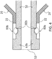
- FIG. 4 shows that a thick portion 82b of a connecting tube 80b is in contact with the front end of the inner shaft 50.
- the thick portion 82b in contact with the front end of the inner shaft 50 can gradually transmit a pressing force applied by an operator in the distal direction of the balloon catheter 10, from the inner shaft 50 to the front-end tip 40b through the thick portion 82b of the connecting tube 80b.
- the inner shaft 50 is made of resin having high stiffness
- the front-end tip 40b is made of resin having low stiffness
- the connecting tube 80b is made of resin having higher stiffness than the front-end tip 40b and lower stiffness than the inner shaft 50
- the thick portion 82b having medium stiffness is in contact with the front end of the inner shaft 50, thereby reducing a loss of a pressing force on the boundary 90 between the front end of the inner shaft 50 and the rear end of the front-end tip 40b. This can improve the operability of the balloon catheter 10 for an operator.
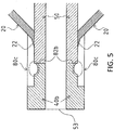
- FIG. 5 shows that the rear end of a connecting tube 80c is extended to the front-end attachment part 22 of the balloon 20 so as to cover the front end of the inner shaft 50 and the front-end attachment part 22 of the balloon 20.
- the connecting tube 80c covering the front-end attachment part 22 of the balloon 20 can reduce the possibility of removal of the balloon 20 from the inner shaft 50 even if a liquid with a high pressure passes through the balloon 20.
- the shapes of the front-end tips 40, 40a, 40b, 40c, and 40d are not limited to those of FIGS. 1 to 6(B) .
- the front-end tip may be tapered with an outside diameter decreasing toward the front end.
- the connecting tubes 80, 80a, 80b, 80c, 100, and 110 have an equal thickness except for the thick portions 82, 82a, 82b, 92, and 102.
- the connecting tubes 80, 80a, 80b, 80c, 100, and 110 are made of resin having higher stiffness than the front-end tips 40, 40a, 40b, 40c, and 40d and lower stiffness than the inner shaft 50
- the connecting tubes 80, 80a, 80b, 80c, 100, and 110 covering the outer surface of the inner shaft 50 are preferably reduced in thickness to further reduce a difference in stiffness between the rear ends of the front-end tips 40, 40a, 40b, 40c, and 40d and the front end of the inner shaft 50; meanwhile, the connecting tubes 80, 80a, 80b, 80c, 100, and 110 covering the outer surfaces of the front-end tips 40, 40a, 40b, 40c, and 40d are preferably increased in thickness.
- the connecting tubes 80, 80a, 80b, 80c, 100, and 110 are preferably increased in thickness from the rear ends to the front ends except for the thick portions 82, 82a, 82b, 92, and 102.
- the thick portions 82, 82a, 82b, 92, and 102 of the connecting tubes 80, 80a, 80b, 80c, 100, and 110 are embedded into the front-end tips 40, 40a, 40b, 40c, and 40d.
Landscapes
- Health & Medical Sciences (AREA)
- Life Sciences & Earth Sciences (AREA)
- Heart & Thoracic Surgery (AREA)
- Hematology (AREA)
- Engineering & Computer Science (AREA)
- Anesthesiology (AREA)
- Biomedical Technology (AREA)
- Pulmonology (AREA)
- Biophysics (AREA)
- Animal Behavior & Ethology (AREA)
- General Health & Medical Sciences (AREA)
- Public Health (AREA)
- Veterinary Medicine (AREA)
- Child & Adolescent Psychology (AREA)
- Vascular Medicine (AREA)
- Media Introduction/Drainage Providing Device (AREA)
Claims (4)
- Ballonkatheter (10) mit:einem Ballon (20);einem an ein vorderes Ende des Ballons geschweißten Innenschaft (50);einer an ein vorderes Ende des Innenschafts geschweißten vorderen Spitze (40, 40a, 40b, 40c, 40d); undeinem Verbindungsrohr (80, 80a, 80b, 80c, 100, 110), das das vordere Ende des Innenschafts und ein hinteres Ende der vorderen Spitze außenseitig ummantelt, dadurch gekennzeichnet, dass:
das Verbindungsrohr eine Verdickung (82, 82a, 82b, 92, 102) hat, die in der vorderen Spitze eingebettet ist. - Ballonkatheter nach Anspruch 1, wobei das Verbindungsrohr (80, 80a, 80b, 80c, 100, 110) aus Harz hergestellt ist, das eine höhere Steifigkeit als die vordere Spitze und eine geringere Steifigkeit als der Innenschaft hat.
- Ballonkatheter nach Anspruch 1 oder 2, wobei die Verdickung (82b) mit dem vorderen Ende des Innenschafts in Kontakt ist.
- Ballonkatheter nach einem der Ansprüche 1 bis 3, wobei ein hinteres Ende des Verbindungsrohrs (80c) das vordere Ende des Ballons ummantelt.
Applications Claiming Priority (1)
| Application Number | Priority Date | Filing Date | Title |
|---|---|---|---|
| JP2014030221A JP5946195B2 (ja) | 2014-02-20 | 2014-02-20 | バルーンカテーテル |
Publications (2)
| Publication Number | Publication Date |
|---|---|
| EP2918304A1 EP2918304A1 (de) | 2015-09-16 |
| EP2918304B1 true EP2918304B1 (de) | 2019-08-07 |
Family
ID=52450015
Family Applications (1)
| Application Number | Title | Priority Date | Filing Date |
|---|---|---|---|
| EP15154085.3A Active EP2918304B1 (de) | 2014-02-20 | 2015-02-06 | Ballonkatheter |
Country Status (4)
| Country | Link |
|---|---|
| US (2) | US9833594B2 (de) |
| EP (1) | EP2918304B1 (de) |
| JP (1) | JP5946195B2 (de) |
| CN (1) | CN104857617B (de) |
Families Citing this family (21)
| Publication number | Priority date | Publication date | Assignee | Title |
|---|---|---|---|---|
| US10850076B2 (en) | 2012-10-26 | 2020-12-01 | Urotronic, Inc. | Balloon catheters for body lumens |
| US11504450B2 (en) | 2012-10-26 | 2022-11-22 | Urotronic, Inc. | Drug-coated balloon catheters for body lumens |
| US10898700B2 (en) | 2012-10-26 | 2021-01-26 | Urotronic, Inc. | Balloon catheters for body lumens |
| US10806830B2 (en) | 2012-10-26 | 2020-10-20 | Urotronic, Inc. | Drug-coated balloon catheters for body lumens |
| CN111166942A (zh) | 2012-10-26 | 2020-05-19 | 优敦力公司 | 用于非血管狭窄的药物涂层球囊导管 |
| US11938287B2 (en) | 2012-10-26 | 2024-03-26 | Urotronic, Inc. | Drug-coated balloon catheters for body lumens |
| US10881839B2 (en) | 2012-10-26 | 2021-01-05 | Urotronic, Inc. | Drug-coated balloon catheters for body lumens |
| CN118320191A (zh) | 2015-04-24 | 2024-07-12 | 优敦力公司 | 用于非血管狭窄的药物涂布的球囊导管 |
| US11904072B2 (en) | 2015-04-24 | 2024-02-20 | Urotronic, Inc. | Drug coated balloon catheters for nonvascular strictures |
| JP6462542B2 (ja) * | 2015-09-15 | 2019-01-30 | 朝日インテック株式会社 | バルーンカテーテル |
| KR101996711B1 (ko) | 2016-03-15 | 2019-07-04 | 아사히 인텍크 가부시키가이샤 | 벌룬 카테터 |
| JP6388316B2 (ja) * | 2016-07-14 | 2018-09-12 | 日本ライフライン株式会社 | バルーンカテーテル |
| KR102097676B1 (ko) * | 2016-09-01 | 2020-04-06 | 아사히 인텍크 가부시키가이샤 | 카테터 |
| WO2018092386A1 (ja) * | 2016-11-21 | 2018-05-24 | テルモ株式会社 | カテーテルおよびカテーテルの製造方法 |
| JP6249544B1 (ja) * | 2016-11-24 | 2017-12-20 | 朝日インテック株式会社 | カテーテル及びバルーンカテーテル |
| JP7028240B2 (ja) * | 2017-03-31 | 2022-03-02 | 日本ゼオン株式会社 | カテーテル用先端チップおよびステントデリバリー装置 |
| CN118949148A (zh) * | 2017-05-05 | 2024-11-15 | 优敦力公司 | 用于体腔的药物涂布球囊导管 |
| JP2022521000A (ja) | 2019-02-22 | 2022-04-04 | ウロトロニック・インコーポレイテッド | 体腔用薬物コーティングバルーンカテーテル |
| CN119236187A (zh) | 2020-02-21 | 2025-01-03 | 吉益医疗公司 | 聚合物包封的药物颗粒 |
| WO2022035890A1 (en) * | 2020-08-11 | 2022-02-17 | Silk Road Medical,Inc. | Balloon catheter for transcarotid procedures |
| JP2025116356A (ja) * | 2024-01-29 | 2025-08-08 | テルモ株式会社 | バルーンカテーテル |
Family Cites Families (11)
| Publication number | Priority date | Publication date | Assignee | Title |
|---|---|---|---|---|
| US5531701A (en) * | 1994-06-06 | 1996-07-02 | Luther Medical Products, Inc. | Over-the-needle catheter |
| US5743874A (en) * | 1994-08-29 | 1998-04-28 | Fischell; Robert E. | Integrated catheter for balloon angioplasty and stent delivery |
| US5762637A (en) * | 1996-08-27 | 1998-06-09 | Scimed Life Systems, Inc. | Insert molded catheter tip |
| US6010521A (en) * | 1997-11-25 | 2000-01-04 | Advanced Cardiovasular Systems, Inc. | Catheter member with bondable layer |
| US6368301B1 (en) * | 1999-12-21 | 2002-04-09 | Advanced Cardiovascular Systems, Inc. | Catheter having a soft distal tip |
| US20030032921A1 (en) * | 2001-08-07 | 2003-02-13 | Advanced Cardiovascular Systems, Inc. | Catheter having a tapered tip |
| US6918920B1 (en) | 2001-11-01 | 2005-07-19 | Advanced Cardiovascular Systems, Inc. | Catheter having an improved distal tip |
| JP2005160536A (ja) * | 2003-11-28 | 2005-06-23 | Nippon Sherwood Medical Industries Ltd | バルーンカテーテル |
| US20060142733A1 (en) | 2004-12-23 | 2006-06-29 | Andrew Forsberg | Catheter tip and method of attaching a catheter tip to a catheter shaft |
| US7678223B2 (en) * | 2006-04-17 | 2010-03-16 | Boston Scientific Scimed, Inc. | Catheter having a multi-section tubular member and method of making the same |
| US9757536B2 (en) | 2012-07-17 | 2017-09-12 | Novartis Ag | Soft tip cannula |
-
2014
- 2014-02-20 JP JP2014030221A patent/JP5946195B2/ja active Active
-
2015
- 2015-01-27 CN CN201510041230.7A patent/CN104857617B/zh not_active Expired - Fee Related
- 2015-01-27 US US14/606,455 patent/US9833594B2/en not_active Expired - Fee Related
- 2015-02-06 EP EP15154085.3A patent/EP2918304B1/de active Active
-
2017
- 2017-10-30 US US15/797,545 patent/US10589064B2/en not_active Expired - Fee Related
Non-Patent Citations (1)
| Title |
|---|
| None * |
Also Published As
| Publication number | Publication date |
|---|---|
| JP5946195B2 (ja) | 2016-07-05 |
| US10589064B2 (en) | 2020-03-17 |
| EP2918304A1 (de) | 2015-09-16 |
| US9833594B2 (en) | 2017-12-05 |
| US20150231375A1 (en) | 2015-08-20 |
| JP2015156880A (ja) | 2015-09-03 |
| CN104857617B (zh) | 2018-06-12 |
| CN104857617A (zh) | 2015-08-26 |
| US20180043131A1 (en) | 2018-02-15 |
Similar Documents
| Publication | Publication Date | Title |
|---|---|---|
| EP2918304B1 (de) | Ballonkatheter | |
| EP2389973B1 (de) | Ballonkatheter | |
| EP3072551B1 (de) | Ballonkatheter | |
| US10617855B2 (en) | Balloon catheter | |
| EP2517749A1 (de) | Katheter | |
| JP6304713B2 (ja) | バルーンカテーテル | |
| EP2399641A1 (de) | Ballonkatheter | |
| EP2944344A1 (de) | Katheter | |
| KR102113902B1 (ko) | 벌룬 카테터 | |
| CN106075701B (zh) | 气囊导管 | |
| EP2399642A1 (de) | Ballonkatheter | |
| EP2910273B1 (de) | Katheter | |
| EP3659665A1 (de) | Ballonkatheter | |
| JP6195396B2 (ja) | バルーンカテーテル | |
| JP2015008766A (ja) | バルーンカテーテル | |
| US10092733B2 (en) | Balloon catheter | |
| JP6639560B2 (ja) | カテーテル | |
| EP4331652A1 (de) | Katheter |
Legal Events
| Date | Code | Title | Description |
|---|---|---|---|
| PUAI | Public reference made under article 153(3) epc to a published international application that has entered the european phase |
Free format text: ORIGINAL CODE: 0009012 |
|
| AK | Designated contracting states |
Kind code of ref document: A1 Designated state(s): AL AT BE BG CH CY CZ DE DK EE ES FI FR GB GR HR HU IE IS IT LI LT LU LV MC MK MT NL NO PL PT RO RS SE SI SK SM TR |
|
| AX | Request for extension of the european patent |
Extension state: BA ME |
|
| 17P | Request for examination filed |
Effective date: 20150930 |
|
| RBV | Designated contracting states (corrected) |
Designated state(s): AL AT BE BG CH CY CZ DE DK EE ES FI FR GB GR HR HU IE IS IT LI LT LU LV MC MK MT NL NO PL PT RO RS SE SI SK SM TR |
|
| RAP1 | Party data changed (applicant data changed or rights of an application transferred) |
Owner name: ASAHI INTECC CO., LTD. |
|
| GRAP | Despatch of communication of intention to grant a patent |
Free format text: ORIGINAL CODE: EPIDOSNIGR1 |
|
| STAA | Information on the status of an ep patent application or granted ep patent |
Free format text: STATUS: GRANT OF PATENT IS INTENDED |
|
| RIC1 | Information provided on ipc code assigned before grant |
Ipc: A61M 25/00 20060101AFI20190117BHEP Ipc: A61M 25/10 20130101ALI20190117BHEP |
|
| INTG | Intention to grant announced |
Effective date: 20190220 |
|
| GRAS | Grant fee paid |
Free format text: ORIGINAL CODE: EPIDOSNIGR3 |
|
| GRAA | (expected) grant |
Free format text: ORIGINAL CODE: 0009210 |
|
| STAA | Information on the status of an ep patent application or granted ep patent |
Free format text: STATUS: THE PATENT HAS BEEN GRANTED |
|
| AK | Designated contracting states |
Kind code of ref document: B1 Designated state(s): AL AT BE BG CH CY CZ DE DK EE ES FI FR GB GR HR HU IE IS IT LI LT LU LV MC MK MT NL NO PL PT RO RS SE SI SK SM TR |
|
| REG | Reference to a national code |
Ref country code: GB Ref legal event code: FG4D |
|
| RIN1 | Information on inventor provided before grant (corrected) |
Inventor name: KUBO, YUTA Inventor name: IKEGAYA, MICHIHIRO Inventor name: KANEKO, YOSHIKI |
|
| REG | Reference to a national code |
Ref country code: CH Ref legal event code: EP Ref country code: AT Ref legal event code: REF Ref document number: 1162863 Country of ref document: AT Kind code of ref document: T Effective date: 20190815 |
|
| REG | Reference to a national code |
Ref country code: DE Ref legal event code: R096 Ref document number: 602015035080 Country of ref document: DE |
|
| REG | Reference to a national code |
Ref country code: IE Ref legal event code: FG4D |
|
| REG | Reference to a national code |
Ref country code: NL Ref legal event code: MP Effective date: 20190807 |
|
| REG | Reference to a national code |
Ref country code: LT Ref legal event code: MG4D |
|
| PG25 | Lapsed in a contracting state [announced via postgrant information from national office to epo] |
Ref country code: HR Free format text: LAPSE BECAUSE OF FAILURE TO SUBMIT A TRANSLATION OF THE DESCRIPTION OR TO PAY THE FEE WITHIN THE PRESCRIBED TIME-LIMIT Effective date: 20190807 Ref country code: LT Free format text: LAPSE BECAUSE OF FAILURE TO SUBMIT A TRANSLATION OF THE DESCRIPTION OR TO PAY THE FEE WITHIN THE PRESCRIBED TIME-LIMIT Effective date: 20190807 Ref country code: NO Free format text: LAPSE BECAUSE OF FAILURE TO SUBMIT A TRANSLATION OF THE DESCRIPTION OR TO PAY THE FEE WITHIN THE PRESCRIBED TIME-LIMIT Effective date: 20191107 Ref country code: FI Free format text: LAPSE BECAUSE OF FAILURE TO SUBMIT A TRANSLATION OF THE DESCRIPTION OR TO PAY THE FEE WITHIN THE PRESCRIBED TIME-LIMIT Effective date: 20190807 Ref country code: SE Free format text: LAPSE BECAUSE OF FAILURE TO SUBMIT A TRANSLATION OF THE DESCRIPTION OR TO PAY THE FEE WITHIN THE PRESCRIBED TIME-LIMIT Effective date: 20190807 Ref country code: PT Free format text: LAPSE BECAUSE OF FAILURE TO SUBMIT A TRANSLATION OF THE DESCRIPTION OR TO PAY THE FEE WITHIN THE PRESCRIBED TIME-LIMIT Effective date: 20191209 Ref country code: BG Free format text: LAPSE BECAUSE OF FAILURE TO SUBMIT A TRANSLATION OF THE DESCRIPTION OR TO PAY THE FEE WITHIN THE PRESCRIBED TIME-LIMIT Effective date: 20191107 Ref country code: NL Free format text: LAPSE BECAUSE OF FAILURE TO SUBMIT A TRANSLATION OF THE DESCRIPTION OR TO PAY THE FEE WITHIN THE PRESCRIBED TIME-LIMIT Effective date: 20190807 |
|
| REG | Reference to a national code |
Ref country code: AT Ref legal event code: MK05 Ref document number: 1162863 Country of ref document: AT Kind code of ref document: T Effective date: 20190807 |
|
| PG25 | Lapsed in a contracting state [announced via postgrant information from national office to epo] |
Ref country code: IS Free format text: LAPSE BECAUSE OF FAILURE TO SUBMIT A TRANSLATION OF THE DESCRIPTION OR TO PAY THE FEE WITHIN THE PRESCRIBED TIME-LIMIT Effective date: 20191207 Ref country code: RS Free format text: LAPSE BECAUSE OF FAILURE TO SUBMIT A TRANSLATION OF THE DESCRIPTION OR TO PAY THE FEE WITHIN THE PRESCRIBED TIME-LIMIT Effective date: 20190807 Ref country code: LV Free format text: LAPSE BECAUSE OF FAILURE TO SUBMIT A TRANSLATION OF THE DESCRIPTION OR TO PAY THE FEE WITHIN THE PRESCRIBED TIME-LIMIT Effective date: 20190807 Ref country code: ES Free format text: LAPSE BECAUSE OF FAILURE TO SUBMIT A TRANSLATION OF THE DESCRIPTION OR TO PAY THE FEE WITHIN THE PRESCRIBED TIME-LIMIT Effective date: 20190807 Ref country code: AL Free format text: LAPSE BECAUSE OF FAILURE TO SUBMIT A TRANSLATION OF THE DESCRIPTION OR TO PAY THE FEE WITHIN THE PRESCRIBED TIME-LIMIT Effective date: 20190807 Ref country code: GR Free format text: LAPSE BECAUSE OF FAILURE TO SUBMIT A TRANSLATION OF THE DESCRIPTION OR TO PAY THE FEE WITHIN THE PRESCRIBED TIME-LIMIT Effective date: 20191108 |
|
| PG25 | Lapsed in a contracting state [announced via postgrant information from national office to epo] |
Ref country code: TR Free format text: LAPSE BECAUSE OF FAILURE TO SUBMIT A TRANSLATION OF THE DESCRIPTION OR TO PAY THE FEE WITHIN THE PRESCRIBED TIME-LIMIT Effective date: 20190807 |
|
| PG25 | Lapsed in a contracting state [announced via postgrant information from national office to epo] |
Ref country code: AT Free format text: LAPSE BECAUSE OF FAILURE TO SUBMIT A TRANSLATION OF THE DESCRIPTION OR TO PAY THE FEE WITHIN THE PRESCRIBED TIME-LIMIT Effective date: 20190807 Ref country code: PL Free format text: LAPSE BECAUSE OF FAILURE TO SUBMIT A TRANSLATION OF THE DESCRIPTION OR TO PAY THE FEE WITHIN THE PRESCRIBED TIME-LIMIT Effective date: 20190807 Ref country code: IT Free format text: LAPSE BECAUSE OF FAILURE TO SUBMIT A TRANSLATION OF THE DESCRIPTION OR TO PAY THE FEE WITHIN THE PRESCRIBED TIME-LIMIT Effective date: 20190807 Ref country code: RO Free format text: LAPSE BECAUSE OF FAILURE TO SUBMIT A TRANSLATION OF THE DESCRIPTION OR TO PAY THE FEE WITHIN THE PRESCRIBED TIME-LIMIT Effective date: 20190807 Ref country code: EE Free format text: LAPSE BECAUSE OF FAILURE TO SUBMIT A TRANSLATION OF THE DESCRIPTION OR TO PAY THE FEE WITHIN THE PRESCRIBED TIME-LIMIT Effective date: 20190807 Ref country code: DK Free format text: LAPSE BECAUSE OF FAILURE TO SUBMIT A TRANSLATION OF THE DESCRIPTION OR TO PAY THE FEE WITHIN THE PRESCRIBED TIME-LIMIT Effective date: 20190807 |
|
| PG25 | Lapsed in a contracting state [announced via postgrant information from national office to epo] |
Ref country code: SM Free format text: LAPSE BECAUSE OF FAILURE TO SUBMIT A TRANSLATION OF THE DESCRIPTION OR TO PAY THE FEE WITHIN THE PRESCRIBED TIME-LIMIT Effective date: 20190807 Ref country code: IS Free format text: LAPSE BECAUSE OF FAILURE TO SUBMIT A TRANSLATION OF THE DESCRIPTION OR TO PAY THE FEE WITHIN THE PRESCRIBED TIME-LIMIT Effective date: 20200224 Ref country code: CZ Free format text: LAPSE BECAUSE OF FAILURE TO SUBMIT A TRANSLATION OF THE DESCRIPTION OR TO PAY THE FEE WITHIN THE PRESCRIBED TIME-LIMIT Effective date: 20190807 Ref country code: SK Free format text: LAPSE BECAUSE OF FAILURE TO SUBMIT A TRANSLATION OF THE DESCRIPTION OR TO PAY THE FEE WITHIN THE PRESCRIBED TIME-LIMIT Effective date: 20190807 |
|
| REG | Reference to a national code |
Ref country code: DE Ref legal event code: R097 Ref document number: 602015035080 Country of ref document: DE |
|
| PLBE | No opposition filed within time limit |
Free format text: ORIGINAL CODE: 0009261 |
|
| STAA | Information on the status of an ep patent application or granted ep patent |
Free format text: STATUS: NO OPPOSITION FILED WITHIN TIME LIMIT |
|
| PG2D | Information on lapse in contracting state deleted |
Ref country code: IS |
|
| 26N | No opposition filed |
Effective date: 20200603 |
|
| PG25 | Lapsed in a contracting state [announced via postgrant information from national office to epo] |
Ref country code: SI Free format text: LAPSE BECAUSE OF FAILURE TO SUBMIT A TRANSLATION OF THE DESCRIPTION OR TO PAY THE FEE WITHIN THE PRESCRIBED TIME-LIMIT Effective date: 20190807 |
|
| REG | Reference to a national code |
Ref country code: CH Ref legal event code: PL |
|
| REG | Reference to a national code |
Ref country code: BE Ref legal event code: MM Effective date: 20200229 |
|
| PG25 | Lapsed in a contracting state [announced via postgrant information from national office to epo] |
Ref country code: MC Free format text: LAPSE BECAUSE OF FAILURE TO SUBMIT A TRANSLATION OF THE DESCRIPTION OR TO PAY THE FEE WITHIN THE PRESCRIBED TIME-LIMIT Effective date: 20190807 Ref country code: LU Free format text: LAPSE BECAUSE OF NON-PAYMENT OF DUE FEES Effective date: 20200206 |
|
| PG25 | Lapsed in a contracting state [announced via postgrant information from national office to epo] |
Ref country code: CH Free format text: LAPSE BECAUSE OF NON-PAYMENT OF DUE FEES Effective date: 20200229 Ref country code: LI Free format text: LAPSE BECAUSE OF NON-PAYMENT OF DUE FEES Effective date: 20200229 |
|
| PG25 | Lapsed in a contracting state [announced via postgrant information from national office to epo] |
Ref country code: IE Free format text: LAPSE BECAUSE OF NON-PAYMENT OF DUE FEES Effective date: 20200206 |
|
| PG25 | Lapsed in a contracting state [announced via postgrant information from national office to epo] |
Ref country code: BE Free format text: LAPSE BECAUSE OF NON-PAYMENT OF DUE FEES Effective date: 20200229 |
|
| PG25 | Lapsed in a contracting state [announced via postgrant information from national office to epo] |
Ref country code: MT Free format text: LAPSE BECAUSE OF FAILURE TO SUBMIT A TRANSLATION OF THE DESCRIPTION OR TO PAY THE FEE WITHIN THE PRESCRIBED TIME-LIMIT Effective date: 20190807 Ref country code: CY Free format text: LAPSE BECAUSE OF FAILURE TO SUBMIT A TRANSLATION OF THE DESCRIPTION OR TO PAY THE FEE WITHIN THE PRESCRIBED TIME-LIMIT Effective date: 20190807 |
|
| PG25 | Lapsed in a contracting state [announced via postgrant information from national office to epo] |
Ref country code: MK Free format text: LAPSE BECAUSE OF FAILURE TO SUBMIT A TRANSLATION OF THE DESCRIPTION OR TO PAY THE FEE WITHIN THE PRESCRIBED TIME-LIMIT Effective date: 20190807 |
|
| PGFP | Annual fee paid to national office [announced via postgrant information from national office to epo] |
Ref country code: FR Payment date: 20230221 Year of fee payment: 9 |
|
| PGFP | Annual fee paid to national office [announced via postgrant information from national office to epo] |
Ref country code: GB Payment date: 20230221 Year of fee payment: 9 Ref country code: DE Payment date: 20230216 Year of fee payment: 9 |
|
| REG | Reference to a national code |
Ref country code: DE Ref legal event code: R119 Ref document number: 602015035080 Country of ref document: DE |
|
| GBPC | Gb: european patent ceased through non-payment of renewal fee |
Effective date: 20240206 |
|
| PG25 | Lapsed in a contracting state [announced via postgrant information from national office to epo] |
Ref country code: DE Free format text: LAPSE BECAUSE OF NON-PAYMENT OF DUE FEES Effective date: 20240903 |
|
| PG25 | Lapsed in a contracting state [announced via postgrant information from national office to epo] |
Ref country code: GB Free format text: LAPSE BECAUSE OF NON-PAYMENT OF DUE FEES Effective date: 20240206 |
|
| PG25 | Lapsed in a contracting state [announced via postgrant information from national office to epo] |
Ref country code: FR Free format text: LAPSE BECAUSE OF NON-PAYMENT OF DUE FEES Effective date: 20240229 |
|
| PG25 | Lapsed in a contracting state [announced via postgrant information from national office to epo] |
Ref country code: GB Free format text: LAPSE BECAUSE OF NON-PAYMENT OF DUE FEES Effective date: 20240206 Ref country code: FR Free format text: LAPSE BECAUSE OF NON-PAYMENT OF DUE FEES Effective date: 20240229 Ref country code: DE Free format text: LAPSE BECAUSE OF NON-PAYMENT OF DUE FEES Effective date: 20240903 |