EP2918312B1 - Ascenseur par gravité - Google Patents
Ascenseur par gravité Download PDFInfo
- Publication number
- EP2918312B1 EP2918312B1 EP15164718.7A EP15164718A EP2918312B1 EP 2918312 B1 EP2918312 B1 EP 2918312B1 EP 15164718 A EP15164718 A EP 15164718A EP 2918312 B1 EP2918312 B1 EP 2918312B1
- Authority
- EP
- European Patent Office
- Prior art keywords
- elevator according
- car
- main
- cable
- elevator
- Prior art date
- Legal status (The legal status is an assumption and is not a legal conclusion. Google has not performed a legal analysis and makes no representation as to the accuracy of the status listed.)
- Not-in-force
Links
- 230000005484 gravity Effects 0.000 title claims description 15
- 238000005520 cutting process Methods 0.000 claims description 20
- 230000009194 climbing Effects 0.000 claims description 13
- 239000002360 explosive Substances 0.000 claims description 6
- 230000009977 dual effect Effects 0.000 claims description 5
- XLYOFNOQVPJJNP-UHFFFAOYSA-N water Substances O XLYOFNOQVPJJNP-UHFFFAOYSA-N 0.000 description 26
- 238000001816 cooling Methods 0.000 description 8
- 229910000831 Steel Inorganic materials 0.000 description 7
- 239000010959 steel Substances 0.000 description 7
- 230000005496 eutectics Effects 0.000 description 6
- 239000000463 material Substances 0.000 description 6
- 230000008018 melting Effects 0.000 description 6
- 238000002844 melting Methods 0.000 description 6
- 239000000498 cooling water Substances 0.000 description 5
- 239000000446 fuel Substances 0.000 description 5
- 230000005611 electricity Effects 0.000 description 4
- 230000005540 biological transmission Effects 0.000 description 3
- 238000010276 construction Methods 0.000 description 3
- 238000009434 installation Methods 0.000 description 3
- 239000003758 nuclear fuel Substances 0.000 description 3
- 238000013021 overheating Methods 0.000 description 3
- 239000013535 sea water Substances 0.000 description 3
- 239000002699 waste material Substances 0.000 description 3
- 230000004888 barrier function Effects 0.000 description 2
- 230000036461 convulsion Effects 0.000 description 2
- 239000006023 eutectic alloy Substances 0.000 description 2
- 238000007667 floating Methods 0.000 description 2
- 239000007789 gas Substances 0.000 description 2
- 230000002706 hydrostatic effect Effects 0.000 description 2
- 239000000155 melt Substances 0.000 description 2
- 229910052760 oxygen Inorganic materials 0.000 description 2
- 239000001301 oxygen Substances 0.000 description 2
- 229920000642 polymer Polymers 0.000 description 2
- 238000010248 power generation Methods 0.000 description 2
- 238000007789 sealing Methods 0.000 description 2
- 229910000975 Carbon steel Inorganic materials 0.000 description 1
- 238000006424 Flood reaction Methods 0.000 description 1
- 230000003213 activating effect Effects 0.000 description 1
- 230000004075 alteration Effects 0.000 description 1
- 238000005422 blasting Methods 0.000 description 1
- 238000007664 blowing Methods 0.000 description 1
- 239000010962 carbon steel Substances 0.000 description 1
- 239000000919 ceramic Substances 0.000 description 1
- 230000000295 complement effect Effects 0.000 description 1
- 239000004567 concrete Substances 0.000 description 1
- 229910052593 corundum Inorganic materials 0.000 description 1
- 239000010431 corundum Substances 0.000 description 1
- 230000006378 damage Effects 0.000 description 1
- 238000010586 diagram Methods 0.000 description 1
- 238000006073 displacement reaction Methods 0.000 description 1
- 238000009826 distribution Methods 0.000 description 1
- 230000000694 effects Effects 0.000 description 1
- 238000005530 etching Methods 0.000 description 1
- 230000008020 evaporation Effects 0.000 description 1
- 238000001704 evaporation Methods 0.000 description 1
- 239000012530 fluid Substances 0.000 description 1
- 239000006260 foam Substances 0.000 description 1
- 238000010438 heat treatment Methods 0.000 description 1
- 239000011372 high-strength concrete Substances 0.000 description 1
- 239000011810 insulating material Substances 0.000 description 1
- 230000007257 malfunction Effects 0.000 description 1
- 238000004519 manufacturing process Methods 0.000 description 1
- 239000002184 metal Substances 0.000 description 1
- 239000000203 mixture Substances 0.000 description 1
- 239000000843 powder Substances 0.000 description 1
- 238000005086 pumping Methods 0.000 description 1
- 230000005855 radiation Effects 0.000 description 1
- 239000012857 radioactive material Substances 0.000 description 1
- 238000004513 sizing Methods 0.000 description 1
- 239000000779 smoke Substances 0.000 description 1
- 239000002689 soil Substances 0.000 description 1
- 239000007787 solid Substances 0.000 description 1
- 239000010935 stainless steel Substances 0.000 description 1
- 229910001220 stainless steel Inorganic materials 0.000 description 1
- 238000003860 storage Methods 0.000 description 1
- 239000002887 superconductor Substances 0.000 description 1
- 230000003966 vascular damage Effects 0.000 description 1
- 238000003466 welding Methods 0.000 description 1
Images


Classifications
-
- G—PHYSICS
- G21—NUCLEAR PHYSICS; NUCLEAR ENGINEERING
- G21C—NUCLEAR REACTORS
- G21C15/00—Cooling arrangements within the pressure vessel containing the core; Selection of specific coolants
- G21C15/18—Emergency cooling arrangements; Removing shut-down heat
-
- A—HUMAN NECESSITIES
- A62—LIFE-SAVING; FIRE-FIGHTING
- A62B—DEVICES, APPARATUS OR METHODS FOR LIFE-SAVING
- A62B1/00—Devices for lowering persons from buildings or the like
- A62B1/02—Devices for lowering persons from buildings or the like by making use of rescue cages, bags, or the like
-
- B—PERFORMING OPERATIONS; TRANSPORTING
- B66—HOISTING; LIFTING; HAULING
- B66B—ELEVATORS; ESCALATORS OR MOVING WALKWAYS
- B66B11/00—Main component parts of lifts in, or associated with, buildings or other structures
- B66B11/04—Driving gear ; Details thereof, e.g. seals
- B66B11/0492—Driving gear ; Details thereof, e.g. seals actuated by other systems, e.g. combustion engines
-
- B—PERFORMING OPERATIONS; TRANSPORTING
- B66—HOISTING; LIFTING; HAULING
- B66B—ELEVATORS; ESCALATORS OR MOVING WALKWAYS
- B66B5/00—Applications of checking, fault-correcting, or safety devices in elevators
- B66B5/02—Applications of checking, fault-correcting, or safety devices in elevators responsive to abnormal operating conditions
- B66B5/027—Applications of checking, fault-correcting, or safety devices in elevators responsive to abnormal operating conditions to permit passengers to leave an elevator car in case of failure, e.g. moving the car to a reference floor or unlocking the door
-
- G—PHYSICS
- G21—NUCLEAR PHYSICS; NUCLEAR ENGINEERING
- G21C—NUCLEAR REACTORS
- G21C13/00—Pressure vessels; Containment vessels; Containment in general
- G21C13/02—Details
-
- G—PHYSICS
- G21—NUCLEAR PHYSICS; NUCLEAR ENGINEERING
- G21C—NUCLEAR REACTORS
- G21C9/00—Emergency protection arrangements structurally associated with the reactor, e.g. safety valves provided with pressure equalisation devices
- G21C9/02—Means for effecting very rapid reduction of the reactivity factor under fault conditions, e.g. reactor fuse; Control elements having arrangements activated in an emergency
- G21C9/022—Reactor fuses
-
- G—PHYSICS
- G21—NUCLEAR PHYSICS; NUCLEAR ENGINEERING
- G21D—NUCLEAR POWER PLANT
- G21D1/00—Details of nuclear power plant
-
- G—PHYSICS
- G21—NUCLEAR PHYSICS; NUCLEAR ENGINEERING
- G21D—NUCLEAR POWER PLANT
- G21D1/00—Details of nuclear power plant
- G21D1/02—Arrangements of auxiliary equipment
-
- G—PHYSICS
- G21—NUCLEAR PHYSICS; NUCLEAR ENGINEERING
- G21D—NUCLEAR POWER PLANT
- G21D3/00—Control of nuclear power plant
- G21D3/04—Safety arrangements
- G21D3/06—Safety arrangements responsive to faults within the plant
-
- Y—GENERAL TAGGING OF NEW TECHNOLOGICAL DEVELOPMENTS; GENERAL TAGGING OF CROSS-SECTIONAL TECHNOLOGIES SPANNING OVER SEVERAL SECTIONS OF THE IPC; TECHNICAL SUBJECTS COVERED BY FORMER USPC CROSS-REFERENCE ART COLLECTIONS [XRACs] AND DIGESTS
- Y02—TECHNOLOGIES OR APPLICATIONS FOR MITIGATION OR ADAPTATION AGAINST CLIMATE CHANGE
- Y02E—REDUCTION OF GREENHOUSE GAS [GHG] EMISSIONS, RELATED TO ENERGY GENERATION, TRANSMISSION OR DISTRIBUTION
- Y02E30/00—Energy generation of nuclear origin
- Y02E30/30—Nuclear fission reactors
Definitions
- the present invention relates to a gravity, elevator.
- a single-use lift elevator for vertical tunnels that can be used in a nuclear power plant or in other installations and situations in which the escape requires going up for operator evacuation in the event of an emergency.
- Document US 20110203877 discloses an elevator safety rescue system with an electro-hydraulic system particularly suited for use in rack and pinion drive elevators installed with tall towers, mines, smoke stacks, and other structures having relatively large elevations or depths.
- the system includes a positive displacement hydraulic pump driven by the output shaft of an electric elevator drive motor.
- An electro-hydraulic valve is electrically powered to maintain an open condition to allow unrestricted hydraulic flow through the pump during normal operation.
- electrical power is terminated to the valve, causing the valve to close and thus requiring all hydraulic fluid to pass through a restrictor
- the object of the invention is an emergency gravity elevator for the exit of operators according to the claims.
- a power plant or other installations and situations in which the escape requires going up comprise elevators in vertical tunnels to access the underground buildings and tunnels, these elevators being able to be of two types, some being electrically operated so that in normal operating conditions the operators can go up and down, and others being gravity elevators, without any need for electricity, which only allow going up and are used exclusively in the event of an emergency to escape from inside the power plant.
- the gravity elevators particularly which are equivalent to emergency elevators that do not require electricity for their exclusive climbing operation, are preferably installed parallel to the elevator for normal use in the vertical escape tunnels and are designed to operate without a motor and without electricity, since they work due to passive elevation using the force of gravity.
- These elevators can also be used in other installations and situations in which the escape requires going up.
- the gravity elevator which is the object of the present invention, has all the typical constructive elements of any elevator, including all the safety elements, but does not include a motor and therefore has no electric or electronic components, and it is an elevator that can only be used once for a single climb.
- the elevator car is anchored to the ground from where the emergency climb must take place by means of a restraint cable which can be cut from inside said car in order to use the elevator in the event of an emergency.
- the elevator car is secured to a main cable at the opposite end of which, after looping around a main sheave, there is located a main counterweight which, when the restraint cable is cut, will cause passive elevation of the car with its occupants inside due to gravity.
- a cutting element preferably an explosive type cutting element
- manual shears suitably sized so that they can be used by a person of average constitution for cutting the cable manually further being contemplated. Therefore, if upon activating the explosive cable cutting element, which is preferably a dual charge element, the pyrotechnic element fails both times the cable could be cut manually by means of the mentioned shears. Furthermore, all the cavities and actuators necessary for being able to operate the cable cutter from inside as well as for being able to manually cut the cable are placed in the elevator car.
- the tension or weight exerted by the main counterweight is slightly greater, by approximately 20%, than the empty weight of the car plus the weight corresponding to the main cable, such that if one or two people enter the car and cut the restraint cable thereof, they will begin to climb up to the surface by the tractive force exerted by gravity as a result of the excess weight of the main counterweight, which maintains a virtually constant climbing tension.
- the emergency elevator of the invention also contemplates the existence of a system of secondary counterweights. Therefore, if the number of people entering the elevator car to climb up and escape to the surface means that the tension of the main counterweight is not enough to cause the car to climb, secondary cables which are each attached to a secondary counterweight and to a ground anchor will be anchored to it. Once the necessary secondary cables are anchored, the ground anchors of said secondary cables are cut such that the weight of each secondary counterweight transmits the corresponding complementary climbing tension. This occurs until the climb begins.
- Said systems can comprise:
- the safety tunnels for external connections and services are preferably vertical, as is the implementation of the different sets of pipes, which are always arranged vertically.
- the power plant has a transmission line for the generated electric power coming out of the high-low voltage alternators located in an underground building and taking it to the high voltage transformers located in the exterior for transmitting the power to the transmission and distribution network.
- This line mainly has a superconductor cable to reduce losses in connection between the alternator and high voltage transformers located on the surface.
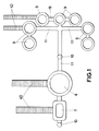
- Figure 1 shows the main buildings and rooms, which will be buried, of the power plant for example in a plan view during the construction of the power plant, in which an open pit has been dug using access ramps 40 to the burying levels and the main buildings, namely, the containment building 6, the generation building 7, the different waste and nuclear fuel buildings or warehouses 9, as well as the tunnels 11 horizontally connecting the different buildings with one another, and the vertical tunnels 10 connecting said horizontal tunnels 11 with the surface, have subsequently been built.
- FIG. 2 which depicts an already built power plant
- all the components of the power plant except the transformer and power plant control building 5 are buried, particularly the containment building 6, with the reactor and the core, the generation building 7, and the fuel element and waste buildings or warehouses 9.
- the control and electrical transformer building 5 located on the surface is electrically connected with the components of the power generation building (7) for transmitting the generated electric power.
- the buried components are located below the level of a main cooling water tank or basin 8 which is connected with an inexhaustible water source such as the sea 16 and located at a sufficient design depth, according to the features of the reactor 1 and the sizing of the design power thereof, the active nuclear part being underground, and only the connection and transmission infrastructure 5 for connecting and transmitting the energy produced to the power grid as well as auxiliary components being located on the surface.
- the terrain where the underground power plant is going to be located is excavated, and after building the plant on said terrain according to suitable construction criteria, such as construction of a concrete compartment, and taking into consideration earthquake-resistance criteria, part of the excavated soil is used to bury the power plant, such that said plant is buried and below the level of the main cooling water tank, i.e., below the sea 16, as well as the main basin 8.
- suitable construction criteria such as construction of a concrete compartment, and taking into consideration earthquake-resistance criteria
- the containment building 6 internally comprises the reactor vessel 2 inside which the core vessel with the reactor core 1 is located.
- the core 1 is the reactor itself and is formed by fissionable fuel, and it is where a nuclear accident can take place if the temperature thereof gets out of control, being able to melt and forming what is referred to as corium or magma resulting from the elements of the core 1 melting, consisting of nuclear fuel, the covering of the fuel elements and the remaining components of the core with which it comes into contact.
- the core vessel 1 is a pressure vessel built from carbon steel with a thickness between 20 and 25 cm and with other internal steel coverings and it is the first barrier against the exit of corium.
- the reactor vessel 2 is the second safety container of the core 1 of the reactor and is built from special steel with a thickness not less than 20 cm.
- the containment building 6 is the final barrier for containing corium in the event of an accident and is built from high-strength concrete with a thickness of at least 150 cm with an inner lead covering. This building is connected with the power production building 7 and with the nuclear fuel and waste warehouses 9.
- the different underground rooms or buildings are communicated with one another by means of horizontal tunnels 11 and with the outside by means of vertical tunnels 10, allowing the transit of operators between the different buildings and with the outside.
- the horizontal tunnels 11 further comprise preferably manually operated safety hatches 12 which allow isolating the different rooms from one another in the event of an emergency for the main purpose of being able to flood the different rooms with the cooling water from the main water tank or basin 8.
- the vertical tunnels 11 are arranged in different places in the power plant to facilitate the operator exit in the event of an emergency.
- Said vertical tunnels 11 preferably comprise electric elevators for use during the normal operation of the power plant, and gravity elevators 100 not requiring electric power and only allowing climbing for operator evacuation in the event of an emergency.
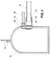
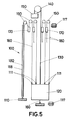
- FIG. 4 and 5 show a diagram of one of said elevators, which constitute an embodiment of the present invention.
- the elevator 100 in question conventionally comprises a car 120 secured at the top by a main cable 130 looped around a main sheave 140 and incorporates at its opposite end a main counterweight 150, with the particularity that said car 120 is anchored to the ground by means of a restraint cable 160, the weight of said main counterweight 150 being slightly greater by approximately 20%, than the empty weight of the car 120 plus the weight of the main cable 130, such that if one or two people enter the car and cut the restraint cable, the car climbs as the counterweight falls due to gravity.
- the elevator has an explosive cutting element for cutting said restraint cable 160 consisting of a dual charge detonating device, as well as a manual cutting element preferably consisting of shears (not depicted).
- the car 120 further has actuators (not depicted) to operate said cutting elements for cutting the restraint cable 160 from the inside, as well as cavities for accessing them and other additional climb control systems that may be incorporated, as will be explained below.
- the elevator 100 has a system of secondary counterweights 170 to allow increasing the car capacity.
- Each of said secondary counterweights 170 is secured to a secondary cable 180 which, looping around a secondary sheave 190, is fixed at one of its ends to a ground anchor 110, whereas at the other end it has means for being fixed to a fastener 111 provided for that purpose in the car 120.
- the elevator 100 can have a greater or lesser number of said counterweights and secondary cables and their corresponding ground anchors and fastenings in the car according to the needs in each case.
- Figure 4 depicts several secondary counterweights 170, only one of them has been depicted in its complete form with its ground anchor 110.
- the elevator can have:
- the car 120 also has mini-oxygen cylinders and masks (not depicted).
- the cooling water tank 8 is a main basin containing borated water and it is connected with the sea 16 as an inexhaustible water and cooling source, and it is in turn connected with at least one secondary basin 82 where a borated solution is stored.
- Said basins are located below sea level 16 and above the buried buildings, being connected with the sea and with one another by means of floats which open gate valves that allow feeding water and maintaining the level thereof.
- the main basin 8 or an underground appendage 81 thereof is connected with the different buildings by means of cooling pipes 13 which carry the borated water from said basin 8 due to gravity, without the need for pumps.
- the main basin 8 and secondary basin 82 comprise covers or plates 83 floating on the water contained therein, said plates 83 being anchored to the bottom of the basins 8, 82.
- Said plates 83 will preferably be built by means of a stainless steel grid covered with a polymer foam that is thick enough for the plates to float on the water, and that is resistant to solar radiation to prevent evaporation of the water and resistant to etching caused by the seawater.
- the mentioned plates or covers 83 are anchored to the bottom of the basins 8, 82 by means of cables 84 with high tensile strength resistant to seawater and with a length equal to the maximum height of the walls of each basin 8, 82.
- Said material can be steel or a polymer.
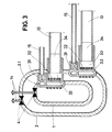
- the cooling pipes 13 connect with the containment building 6 through fuse elements 3 which are incorporated in the walls of the containment building 6, of the reactor vessel 2 and of the core vessel 1. It can evidently be located in only one of the walls of one of the elements.
- Each fuse element 3 comprises a hatch 32 that opens automatically in the event of nuclear reactor overheating which is formed by an eutectic alloy material 32 having features similar to the walls separating the different elements of the reactor from one another, the core vessel 1, the reactor vessel 2 and the containment building 6, but which are susceptible to melting in overheating conditions and communicate each of the elements 1, 2, 6, with at least one cooling pipe 13, preferably more than one pipe, in an attempt to obtain safety redundancy, which in turn connects with the main basin 8.
- the reactor has a double steel vessel and is provided with at least two fuses 3.1, 3.2, one in each of the inner vessel or core vessel 1 and outer vessel or the reactor vessel 2, respectively, connected with independent borated water ducts 13.1, 13.2, each one being able to circulate the borated water between each inner and outer vessel.
- the reactor is enclosed in a containment building 6 also preferably provided with a third fuse 3.3 connected to a third pipe 13.3 to allow the entrance of cooling borated water.
- the fuse 3 is ceramic or metal a hermetic sealing calculated for being melted when a specific temperature is reached and is integrated in the walls of the vessels 1, 2 or of the containment building 6. It is particularly integrated in said walls by means of a solid anchor either by welding or by screws, forming part of the wall as it has the same features as said wall, namely, the same mechanical strength as any other part of the wall, or of the core vessel 1 or the reactor vessel 2, or of the containment building 6.
- the fuses 3 melt suddenly at a predetermined temperature to make way for the borated water that floods and cools the inside of any of the vessels 1, 2 or the containment building 6.
- the fuses 3 comprise a cover made from an eutectic material 32 and designed for being melt when a predetermined or set-point temperature is reached, followed by an insulating material 33 and an insulating cover 34.
- the melting point of the eutectic material will range between 2000 and 2500°C and once the melting temperature is reached, it will melt all of a sudden.
- the eutectic cover 32 melts suddenly, causing the hydrostatic pressure of the water column of the cooling pipe 13 connected to the borated water basin 8 to push the insulating cover 34 on the thermal insulating plug 33, making them enter the core 1 and opening up the access path of the borated water into the building 6 or vessel 1, 2 to cool the reactor.
- the fuse 3 preferably has in its lower part a specific housing for housing a low pressure valve 31, connected with low pressure pipes 15 which open up once the first boil-off gases are produced when the borated water comes into contact with the hot elements of the inside of the vessels 1, 2 or of the building 6. Since the eutectic alloy of the cover 32 melts suddenly due to the effect of the hydrostatic pressure of the water column, at first the water enters the vessels 1, 2 or building 6 because the mentioned low pressure relief valves 31 instantaneously prevent the water column from being pushed upwards or towards the basin 8.
- the reactor is also provided with high pressure and temperature safety valves 4 connected with high pressure pipes 14 for blowing off the high pressure surges that may occur with the entrance of borated water into the core 1 and into the core vessel 2.
- the power plant has a pumping station for recovering the plant by means of extracting the cooling water into the borated water basin through the reactor gas outlet or exhaust pipes (core and core vessel).
- the cooling system using borated water extends not only to the reactor 1, 2 and its containment building 6 but to other buildings such as the power generation building 7 containing the turbines and alternators or the fuel storage building 9 or any other room with radioactive material that must be flooded and cooled in the event of an accident.
- the power plant and all its entrances and exits are surrounded by pyrotechnic rings for blasting the plant in the event of an emergency and permanently sealing it off.
- shape, materials and dimensions may be variable and generally insofar as it is accessory and secondary, provided that it does not alter, change or modify the essential nature of the improvements herein described.
Landscapes
- Engineering & Computer Science (AREA)
- Physics & Mathematics (AREA)
- Plasma & Fusion (AREA)
- General Engineering & Computer Science (AREA)
- High Energy & Nuclear Physics (AREA)
- Emergency Management (AREA)
- Business, Economics & Management (AREA)
- General Health & Medical Sciences (AREA)
- Health & Medical Sciences (AREA)
- Chemical & Material Sciences (AREA)
- Combustion & Propulsion (AREA)
- Civil Engineering (AREA)
- Mechanical Engineering (AREA)
- Structural Engineering (AREA)
- Working Measures On Existing Buildindgs (AREA)
- Maintenance And Inspection Apparatuses For Elevators (AREA)
Claims (12)
- Ascenseur de montée à usage unique pour tunnels verticaux, du type ayant une cabine (120) attachée au-dessus par un câble principal (130) enroulé autour d'une poulie principale (140) et dont l'extrémité opposée incorpore un contrepoids principal (150),
caractérisé en ce que
il fonctionne sans énergie électrique et en utilisant exclusivement la force de gravité, et dans lequel :- ladite cabine (120) est ancrée au sol au moyen d'un câble de retenue (160) ;- le poids dudit contrepoids principal (150) est plus important que le poids vide de la cabine (120), plus le poids du câble principal (130) ; et- il a au moins un élément de coupe explosif et au moins un élément de coupe manuel pour couper le câble de retenue (160). - Ascenseur selon la revendication 1, caractérisé en ce que la cabine (120) comprend des actionneurs pour opérer les éléments de coupe du câble de retenue (160) de l'intérieur.
- Ascenseur selon la revendication 1, caractérisé en ce qu'il comprend des éléments de sécurité et des éléments de contrôle de vitesse d'ascension.
- Ascenseur selon la revendication 1, caractérisé en ce que le poids du contrepoids principal (150) est au moins 20 % plus important que la somme du poids vide de la cabine (120) plus le câble principal (130).
- Ascenseur selon les revendications 1 ou 2, caractérisé en ce que l'élément de coupe explosif est un élément de détonation à double charge.
- Ascenseur selon les revendications 1 ou 2, caractérisé en ce que l'élément de coupe manuel est une cisaille.
- Ascenseur selon la revendication 1, caractérisé en ce qu'il comprend au moins un contrepoids secondaire (170) qui est attaché à un câble secondaire (180) qui, s'enroulant autour d'une poulie secondaire (190), est fixé à l'une de ses extrémités à un ancrage au sol (110) et a à l'autre extrémité des moyens pour être fixé à un élément de serrage (111) pourvu dans la cabine (120).
- Ascenseur selon la revendication 7, caractérisé en ce que la cabine (120) comprend des éléments de coupe pour couper les ancrages des câbles secondaires (180).
- Ascenseur selon la revendication 3, caractérisé en ce qu'il comprend au moins un levier de frein (112) agissant sur au moins un bloc de friction (113) qui se déplace le long d'une voie (114) installée le long du parcours vers le haut.
- Ascenseur selon la revendication 3, caractérisé en ce qu'il comprend au moins un indicateur de vitesse.
- Ascenseur selon la revendication 3, caractérisé en ce qu'il comprend des roues dentées (115) s'engrenant avec une crémaillère (116) installée le long du parcours.
- Ascenseur selon la revendication 3, caractérisé en ce qu'il comprend des amortisseurs à inertie (117) installés à l'extrémité du parcours.
Priority Applications (1)
| Application Number | Priority Date | Filing Date | Title |
|---|---|---|---|
| EP15164718.7A EP2918312B1 (fr) | 2012-07-19 | 2012-07-19 | Ascenseur par gravité |
Applications Claiming Priority (2)
| Application Number | Priority Date | Filing Date | Title |
|---|---|---|---|
| EP12770173.8A EP2814038B1 (fr) | 2012-07-19 | 2012-07-19 | Centrale nucléaire et système de sécurité à élément fusible et à ascenseur gravitationnel |
| EP15164718.7A EP2918312B1 (fr) | 2012-07-19 | 2012-07-19 | Ascenseur par gravité |
Related Parent Applications (2)
| Application Number | Title | Priority Date | Filing Date |
|---|---|---|---|
| EP12770173.8A Division EP2814038B1 (fr) | 2012-07-19 | 2012-07-19 | Centrale nucléaire et système de sécurité à élément fusible et à ascenseur gravitationnel |
| EP12770173.8A Division-Into EP2814038B1 (fr) | 2012-07-19 | 2012-07-19 | Centrale nucléaire et système de sécurité à élément fusible et à ascenseur gravitationnel |
Publications (2)
| Publication Number | Publication Date |
|---|---|
| EP2918312A1 EP2918312A1 (fr) | 2015-09-16 |
| EP2918312B1 true EP2918312B1 (fr) | 2016-09-21 |
Family
ID=53784059
Family Applications (1)
| Application Number | Title | Priority Date | Filing Date |
|---|---|---|---|
| EP15164718.7A Not-in-force EP2918312B1 (fr) | 2012-07-19 | 2012-07-19 | Ascenseur par gravité |
Country Status (1)
| Country | Link |
|---|---|
| EP (1) | EP2918312B1 (fr) |
Families Citing this family (1)
| Publication number | Priority date | Publication date | Assignee | Title |
|---|---|---|---|---|
| CN113955607B (zh) * | 2021-09-23 | 2023-06-27 | 长江勘测规划设计研究有限责任公司 | 一种地下核电厂的箱体式垂直逃生方法 |
Family Cites Families (3)
| Publication number | Priority date | Publication date | Assignee | Title |
|---|---|---|---|---|
| US4971752A (en) * | 1988-12-14 | 1990-11-20 | Parker Louis W | Safety design for nuclear power plants |
| JP4683703B2 (ja) * | 2000-10-20 | 2011-05-18 | 東芝エレベータ株式会社 | マシンルームレスエレベータ |
| US8714312B2 (en) | 2009-06-19 | 2014-05-06 | James L. Tiner | Elevator safety rescue system |
-
2012
- 2012-07-19 EP EP15164718.7A patent/EP2918312B1/fr not_active Not-in-force
Also Published As
| Publication number | Publication date |
|---|---|
| EP2918312A1 (fr) | 2015-09-16 |
Similar Documents
| Publication | Publication Date | Title |
|---|---|---|
| EP2814038B1 (fr) | Centrale nucléaire et système de sécurité à élément fusible et à ascenseur gravitationnel | |
| JP2015524559A5 (fr) | ||
| US4971752A (en) | Safety design for nuclear power plants | |
| JP2022024946A (ja) | 水中交通トンネル | |
| US4442065A (en) | Retrofittable nuclear reactor core catcher | |
| RU2549362C2 (ru) | Подводный модуль для производства электрической энергии | |
| SA517382204B1 (ar) | تنشيط أداة نظام ببئر | |
| JP2018508712A (ja) | 潜水型発電プラットフォーム | |
| US20230392499A1 (en) | Fabricated ocean tunnel structure with escape device and application method thereof | |
| EP2918312B1 (fr) | Ascenseur par gravité | |
| CN203569551U (zh) | 一种新型防结冰浮动式抗冰装置 | |
| JP2017032594A (ja) | 緊急炉心冷却装置を備えた原子力発電所装置。 | |
| Strickland | 24 hours at Fukushima | |
| JP2012242375A (ja) | 原子力発電所装置。 | |
| CN105390169B (zh) | 一种山体深埋式核电站地下核岛厂房 | |
| WO1985000921A1 (fr) | Structure amelioree de reacteur nucleaire s'adaptant egalement a des installations existantes | |
| CN102678169A (zh) | 矿井平巷全自动灾害堵防装置 | |
| JP2016040555A (ja) | 原子力発電所装置。 | |
| JP2016040553A (ja) | 原子力発電所装置。 | |
| CN207498904U (zh) | 防洪闸门 | |
| CN106437849B (zh) | 一种矿山灾害阻隔设备的启动装置 | |
| JP2928610B2 (ja) | 原子力設備 | |
| JP2016027350A (ja) | 原子力発電所装置。 | |
| KR20200145581A (ko) | 해조류형 심층 해저 원자로 | |
| SU1079745A1 (ru) | Устройство дл защиты ворот шлюза от навала судов |
Legal Events
| Date | Code | Title | Description |
|---|---|---|---|
| PUAI | Public reference made under article 153(3) epc to a published international application that has entered the european phase |
Free format text: ORIGINAL CODE: 0009012 |
|
| AC | Divisional application: reference to earlier application |
Ref document number: 2814038 Country of ref document: EP Kind code of ref document: P |
|
| AK | Designated contracting states |
Kind code of ref document: A1 Designated state(s): AL AT BE BG CH CY CZ DE DK EE ES FI FR GB GR HR HU IE IS IT LI LT LU LV MC MK MT NL NO PL PT RO RS SE SI SK SM TR |
|
| AX | Request for extension of the european patent |
Extension state: BA ME |
|
| 17P | Request for examination filed |
Effective date: 20151105 |
|
| RBV | Designated contracting states (corrected) |
Designated state(s): AL AT BE BG CH CY CZ DE DK EE ES FI FR GB GR HR HU IE IS IT LI LT LU LV MC MK MT NL NO PL PT RO RS SE SI SK SM TR |
|
| GRAP | Despatch of communication of intention to grant a patent |
Free format text: ORIGINAL CODE: EPIDOSNIGR1 |
|
| RIC1 | Information provided on ipc code assigned before grant |
Ipc: G21C 9/02 20060101ALN20160301BHEP Ipc: G21D 1/00 20060101ALI20160301BHEP Ipc: G21C 15/18 20060101ALN20160301BHEP Ipc: B66B 5/02 20060101ALI20160301BHEP Ipc: G21D 3/06 20060101ALI20160301BHEP Ipc: G21C 13/02 20060101ALN20160301BHEP Ipc: B66B 11/04 20060101ALI20160301BHEP Ipc: G21D 1/02 20060101ALI20160301BHEP Ipc: E21F 11/00 20060101ALI20160301BHEP Ipc: A62B 1/02 20060101AFI20160301BHEP |
|
| INTG | Intention to grant announced |
Effective date: 20160317 |
|
| GRAS | Grant fee paid |
Free format text: ORIGINAL CODE: EPIDOSNIGR3 |
|
| GRAA | (expected) grant |
Free format text: ORIGINAL CODE: 0009210 |
|
| AC | Divisional application: reference to earlier application |
Ref document number: 2814038 Country of ref document: EP Kind code of ref document: P |
|
| AK | Designated contracting states |
Kind code of ref document: B1 Designated state(s): AL AT BE BG CH CY CZ DE DK EE ES FI FR GB GR HR HU IE IS IT LI LT LU LV MC MK MT NL NO PL PT RO RS SE SI SK SM TR |
|
| REG | Reference to a national code |
Ref country code: GB Ref legal event code: FG4D |
|
| REG | Reference to a national code |
Ref country code: CH Ref legal event code: EP |
|
| REG | Reference to a national code |
Ref country code: AT Ref legal event code: REF Ref document number: 830575 Country of ref document: AT Kind code of ref document: T Effective date: 20161015 |
|
| REG | Reference to a national code |
Ref country code: IE Ref legal event code: FG4D |
|
| REG | Reference to a national code |
Ref country code: DE Ref legal event code: R096 Ref document number: 602012023425 Country of ref document: DE |
|
| REG | Reference to a national code |
Ref country code: LT Ref legal event code: MG4D Ref country code: NL Ref legal event code: MP Effective date: 20160921 |
|
| PG25 | Lapsed in a contracting state [announced via postgrant information from national office to epo] |
Ref country code: RS Free format text: LAPSE BECAUSE OF FAILURE TO SUBMIT A TRANSLATION OF THE DESCRIPTION OR TO PAY THE FEE WITHIN THE PRESCRIBED TIME-LIMIT Effective date: 20160921 Ref country code: NO Free format text: LAPSE BECAUSE OF FAILURE TO SUBMIT A TRANSLATION OF THE DESCRIPTION OR TO PAY THE FEE WITHIN THE PRESCRIBED TIME-LIMIT Effective date: 20161221 Ref country code: LT Free format text: LAPSE BECAUSE OF FAILURE TO SUBMIT A TRANSLATION OF THE DESCRIPTION OR TO PAY THE FEE WITHIN THE PRESCRIBED TIME-LIMIT Effective date: 20160921 Ref country code: FI Free format text: LAPSE BECAUSE OF FAILURE TO SUBMIT A TRANSLATION OF THE DESCRIPTION OR TO PAY THE FEE WITHIN THE PRESCRIBED TIME-LIMIT Effective date: 20160921 |
|
| REG | Reference to a national code |
Ref country code: AT Ref legal event code: MK05 Ref document number: 830575 Country of ref document: AT Kind code of ref document: T Effective date: 20160921 |
|
| PG25 | Lapsed in a contracting state [announced via postgrant information from national office to epo] |
Ref country code: NL Free format text: LAPSE BECAUSE OF FAILURE TO SUBMIT A TRANSLATION OF THE DESCRIPTION OR TO PAY THE FEE WITHIN THE PRESCRIBED TIME-LIMIT Effective date: 20160921 Ref country code: LV Free format text: LAPSE BECAUSE OF FAILURE TO SUBMIT A TRANSLATION OF THE DESCRIPTION OR TO PAY THE FEE WITHIN THE PRESCRIBED TIME-LIMIT Effective date: 20160921 Ref country code: GR Free format text: LAPSE BECAUSE OF FAILURE TO SUBMIT A TRANSLATION OF THE DESCRIPTION OR TO PAY THE FEE WITHIN THE PRESCRIBED TIME-LIMIT Effective date: 20161222 Ref country code: SE Free format text: LAPSE BECAUSE OF FAILURE TO SUBMIT A TRANSLATION OF THE DESCRIPTION OR TO PAY THE FEE WITHIN THE PRESCRIBED TIME-LIMIT Effective date: 20160921 |
|
| PG25 | Lapsed in a contracting state [announced via postgrant information from national office to epo] |
Ref country code: RO Free format text: LAPSE BECAUSE OF FAILURE TO SUBMIT A TRANSLATION OF THE DESCRIPTION OR TO PAY THE FEE WITHIN THE PRESCRIBED TIME-LIMIT Effective date: 20160921 Ref country code: EE Free format text: LAPSE BECAUSE OF FAILURE TO SUBMIT A TRANSLATION OF THE DESCRIPTION OR TO PAY THE FEE WITHIN THE PRESCRIBED TIME-LIMIT Effective date: 20160921 |
|
| PG25 | Lapsed in a contracting state [announced via postgrant information from national office to epo] |
Ref country code: AT Free format text: LAPSE BECAUSE OF FAILURE TO SUBMIT A TRANSLATION OF THE DESCRIPTION OR TO PAY THE FEE WITHIN THE PRESCRIBED TIME-LIMIT Effective date: 20160921 Ref country code: CZ Free format text: LAPSE BECAUSE OF FAILURE TO SUBMIT A TRANSLATION OF THE DESCRIPTION OR TO PAY THE FEE WITHIN THE PRESCRIBED TIME-LIMIT Effective date: 20160921 Ref country code: IS Free format text: LAPSE BECAUSE OF FAILURE TO SUBMIT A TRANSLATION OF THE DESCRIPTION OR TO PAY THE FEE WITHIN THE PRESCRIBED TIME-LIMIT Effective date: 20170121 Ref country code: ES Free format text: LAPSE BECAUSE OF FAILURE TO SUBMIT A TRANSLATION OF THE DESCRIPTION OR TO PAY THE FEE WITHIN THE PRESCRIBED TIME-LIMIT Effective date: 20160921 Ref country code: SM Free format text: LAPSE BECAUSE OF FAILURE TO SUBMIT A TRANSLATION OF THE DESCRIPTION OR TO PAY THE FEE WITHIN THE PRESCRIBED TIME-LIMIT Effective date: 20160921 Ref country code: BE Free format text: LAPSE BECAUSE OF FAILURE TO SUBMIT A TRANSLATION OF THE DESCRIPTION OR TO PAY THE FEE WITHIN THE PRESCRIBED TIME-LIMIT Effective date: 20160921 Ref country code: SK Free format text: LAPSE BECAUSE OF FAILURE TO SUBMIT A TRANSLATION OF THE DESCRIPTION OR TO PAY THE FEE WITHIN THE PRESCRIBED TIME-LIMIT Effective date: 20160921 Ref country code: PT Free format text: LAPSE BECAUSE OF FAILURE TO SUBMIT A TRANSLATION OF THE DESCRIPTION OR TO PAY THE FEE WITHIN THE PRESCRIBED TIME-LIMIT Effective date: 20170123 Ref country code: BG Free format text: LAPSE BECAUSE OF FAILURE TO SUBMIT A TRANSLATION OF THE DESCRIPTION OR TO PAY THE FEE WITHIN THE PRESCRIBED TIME-LIMIT Effective date: 20161221 Ref country code: PL Free format text: LAPSE BECAUSE OF FAILURE TO SUBMIT A TRANSLATION OF THE DESCRIPTION OR TO PAY THE FEE WITHIN THE PRESCRIBED TIME-LIMIT Effective date: 20160921 |
|
| REG | Reference to a national code |
Ref country code: DE Ref legal event code: R097 Ref document number: 602012023425 Country of ref document: DE |
|
| PG25 | Lapsed in a contracting state [announced via postgrant information from national office to epo] |
Ref country code: IT Free format text: LAPSE BECAUSE OF FAILURE TO SUBMIT A TRANSLATION OF THE DESCRIPTION OR TO PAY THE FEE WITHIN THE PRESCRIBED TIME-LIMIT Effective date: 20160921 |
|
| PLBE | No opposition filed within time limit |
Free format text: ORIGINAL CODE: 0009261 |
|
| STAA | Information on the status of an ep patent application or granted ep patent |
Free format text: STATUS: NO OPPOSITION FILED WITHIN TIME LIMIT |
|
| PG25 | Lapsed in a contracting state [announced via postgrant information from national office to epo] |
Ref country code: DK Free format text: LAPSE BECAUSE OF FAILURE TO SUBMIT A TRANSLATION OF THE DESCRIPTION OR TO PAY THE FEE WITHIN THE PRESCRIBED TIME-LIMIT Effective date: 20160921 |
|
| 26N | No opposition filed |
Effective date: 20170622 |
|
| PG25 | Lapsed in a contracting state [announced via postgrant information from national office to epo] |
Ref country code: SI Free format text: LAPSE BECAUSE OF FAILURE TO SUBMIT A TRANSLATION OF THE DESCRIPTION OR TO PAY THE FEE WITHIN THE PRESCRIBED TIME-LIMIT Effective date: 20160921 |
|
| REG | Reference to a national code |
Ref country code: DE Ref legal event code: R119 Ref document number: 602012023425 Country of ref document: DE |
|
| REG | Reference to a national code |
Ref country code: CH Ref legal event code: PL |
|
| GBPC | Gb: european patent ceased through non-payment of renewal fee |
Effective date: 20170719 |
|
| REG | Reference to a national code |
Ref country code: IE Ref legal event code: MM4A |
|
| REG | Reference to a national code |
Ref country code: FR Ref legal event code: ST Effective date: 20180330 |
|
| PG25 | Lapsed in a contracting state [announced via postgrant information from national office to epo] |
Ref country code: GB Free format text: LAPSE BECAUSE OF NON-PAYMENT OF DUE FEES Effective date: 20170719 Ref country code: CH Free format text: LAPSE BECAUSE OF NON-PAYMENT OF DUE FEES Effective date: 20170731 Ref country code: DE Free format text: LAPSE BECAUSE OF NON-PAYMENT OF DUE FEES Effective date: 20180201 Ref country code: IE Free format text: LAPSE BECAUSE OF NON-PAYMENT OF DUE FEES Effective date: 20170719 Ref country code: LI Free format text: LAPSE BECAUSE OF NON-PAYMENT OF DUE FEES Effective date: 20170731 |
|
| PG25 | Lapsed in a contracting state [announced via postgrant information from national office to epo] |
Ref country code: FR Free format text: LAPSE BECAUSE OF NON-PAYMENT OF DUE FEES Effective date: 20170731 |
|
| PG25 | Lapsed in a contracting state [announced via postgrant information from national office to epo] |
Ref country code: LU Free format text: LAPSE BECAUSE OF NON-PAYMENT OF DUE FEES Effective date: 20170719 |
|
| PG25 | Lapsed in a contracting state [announced via postgrant information from national office to epo] |
Ref country code: MT Free format text: LAPSE BECAUSE OF NON-PAYMENT OF DUE FEES Effective date: 20170719 |
|
| PG25 | Lapsed in a contracting state [announced via postgrant information from national office to epo] |
Ref country code: AL Free format text: LAPSE BECAUSE OF FAILURE TO SUBMIT A TRANSLATION OF THE DESCRIPTION OR TO PAY THE FEE WITHIN THE PRESCRIBED TIME-LIMIT Effective date: 20160921 |
|
| PG25 | Lapsed in a contracting state [announced via postgrant information from national office to epo] |
Ref country code: HU Free format text: LAPSE BECAUSE OF FAILURE TO SUBMIT A TRANSLATION OF THE DESCRIPTION OR TO PAY THE FEE WITHIN THE PRESCRIBED TIME-LIMIT; INVALID AB INITIO Effective date: 20120719 Ref country code: MC Free format text: LAPSE BECAUSE OF FAILURE TO SUBMIT A TRANSLATION OF THE DESCRIPTION OR TO PAY THE FEE WITHIN THE PRESCRIBED TIME-LIMIT Effective date: 20160921 |
|
| PG25 | Lapsed in a contracting state [announced via postgrant information from national office to epo] |
Ref country code: CY Free format text: LAPSE BECAUSE OF FAILURE TO SUBMIT A TRANSLATION OF THE DESCRIPTION OR TO PAY THE FEE WITHIN THE PRESCRIBED TIME-LIMIT Effective date: 20160921 |
|
| PG25 | Lapsed in a contracting state [announced via postgrant information from national office to epo] |
Ref country code: MK Free format text: LAPSE BECAUSE OF FAILURE TO SUBMIT A TRANSLATION OF THE DESCRIPTION OR TO PAY THE FEE WITHIN THE PRESCRIBED TIME-LIMIT Effective date: 20160921 |
|
| PG25 | Lapsed in a contracting state [announced via postgrant information from national office to epo] |
Ref country code: TR Free format text: LAPSE BECAUSE OF FAILURE TO SUBMIT A TRANSLATION OF THE DESCRIPTION OR TO PAY THE FEE WITHIN THE PRESCRIBED TIME-LIMIT Effective date: 20160921 |
|
| PG25 | Lapsed in a contracting state [announced via postgrant information from national office to epo] |
Ref country code: HR Free format text: LAPSE BECAUSE OF FAILURE TO SUBMIT A TRANSLATION OF THE DESCRIPTION OR TO PAY THE FEE WITHIN THE PRESCRIBED TIME-LIMIT Effective date: 20160921 |