EP2918322B1 - Vorrichtung zum aufhängen von textilien - Google Patents
Vorrichtung zum aufhängen von textilien Download PDFInfo
- Publication number
- EP2918322B1 EP2918322B1 EP15158588.2A EP15158588A EP2918322B1 EP 2918322 B1 EP2918322 B1 EP 2918322B1 EP 15158588 A EP15158588 A EP 15158588A EP 2918322 B1 EP2918322 B1 EP 2918322B1
- Authority
- EP
- European Patent Office
- Prior art keywords
- plate
- pressure plate
- connecting element
- adjustable connecting
- mounting
- Prior art date
- Legal status (The legal status is an assumption and is not a legal conclusion. Google has not performed a legal analysis and makes no representation as to the accuracy of the status listed.)
- Active
Links
Images


Classifications
-
- A—HUMAN NECESSITIES
- A47—FURNITURE; DOMESTIC ARTICLES OR APPLIANCES; COFFEE MILLS; SPICE MILLS; SUCTION CLEANERS IN GENERAL
- A47H—FURNISHINGS FOR WINDOWS OR DOORS
- A47H13/00—Fastening curtains on curtain rods or rails
- A47H13/01—Fastening curtains on curtain rods or rails by clamps; by clamps attached to hooks or rings
-
- A—HUMAN NECESSITIES
- A01—AGRICULTURE; FORESTRY; ANIMAL HUSBANDRY; HUNTING; TRAPPING; FISHING
- A01K—ANIMAL HUSBANDRY; AVICULTURE; APICULTURE; PISCICULTURE; FISHING; REARING OR BREEDING ANIMALS, NOT OTHERWISE PROVIDED FOR; NEW BREEDS OF ANIMALS
- A01K1/00—Housing animals; Equipment therefor
- A01K1/02—Pigsties; Dog-kennels; Rabbit-hutches or the like
- A01K1/0218—Farrowing or weaning crates
-
- A—HUMAN NECESSITIES
- A63—SPORTS; GAMES; AMUSEMENTS
- A63J—DEVICES FOR THEATRES, CIRCUSES, OR THE LIKE; CONJURING APPLIANCES OR THE LIKE
- A63J1/00—Stage arrangements
- A63J1/02—Scenery; Curtains; Other decorations; Means for moving same
Definitions
- the invention relates to a device for hanging textiles, such as curtains, with a holding body, which is fastened to a fixed structure, a fixedly mounted on the holding body counter-plate, a hinged to the holding body pressure plate, wherein the pressure plate with the counter plate a clip for holding the textile forms, and with an electromagnet, which cooperates with an anchor plate to close the clip.
- Such devices are used, for example, in theaters to suspend curtains, with the possibility of dropping the curtain by opening the clip.
- the pressure plate is designed as a two-armed lever and the anchor plate is adjustably attached to the pressure plate.
- By adjusting an adjustment to the thickness of the textiles to be held is given. Due to the kinematics of such a system, only a small tolerance to variations in thickness is possible, ie that, for example, when wrinkles occur, an insufficient function can occur.
- the switching of the electromagnet is always associated with a caused by the collision of metal parts noise, which is undesirable especially in the theater.
- Object of the present invention is to avoid these disadvantages and to provide a solution that is tolerant of variations in the thickness of the textiles and is silently switchable.
- the anchor plate is mounted on the holding body and is coupled by an adjustable connecting element with the pressure plate, and that the mounting of the anchor plate is arranged on the holding body between the mounting of the pressure plate and the adjustable connecting element.
- the anchor plate not only on the To make pressure plate, but directly on the holder body, and on the other to be achieved by the special arrangement of the pivot axes that the armature plate remains in all positions in the immediate sphere of influence of the electromagnet.
- a kind of four-bar linkage is realized in which a small pivoting of the anchor plate leads to a comparatively large opening of the clip. It is particularly advantageous if the distance between the mounting of the anchor plate and the adjustable connecting element is between 50% and 80% of the distance between the bearing of the pressure plate and the adjustable connecting element. As a result, particularly favorable balance of power can be achieved.
- a main section of the pressure plate and a main section of the anchor plate are arranged substantially parallel to one another. This allows a compact and space-saving design.
- a particularly favorable construction in which the pressure plate is designed as a one-armed lever, can be realized in that an attack surface of the electromagnet is arranged on the anchor plate between the mounting of the anchor plate and the adjustable connecting element.
- the holding body has a U-shaped cross section and that the electromagnet is accommodated therein.
- the pressure plate and the counter plate each have an end region developed by about 45 °. This makes it possible to easily accommodate a possible seam of the process in the expanding space between pressure plate and counter plate.
- a particularly low noise can be achieved in that the adjustable connecting element is mounted on elastomers.
- the device according to the invention consists of a holding body 1 which at the same time forms a housing to which a clamp 2 is attached in order to fasten the device to a fixed structure, for example a rod.
- the clamp 2 has a curved arm 3, which cooperates with an adjustable tongue 4, which can be actuated by a knurled screw 5, to fix the device to a rod, not shown.
- a pressure plate 6 is pivotally mounted about an axis 6a. At the opposite end of the axis 6a, the pressure plate 6 has an angled end portion 6b.
- the pressure plate 6 cooperates with a counter plate 7 to form a clip for holding a curtain or the like.
- the counter plate 7 also has an angled end portion 7b.
- the actuation of the pressure plate 6 is effected by an anchor plate 8 which is pivotally mounted about an axis 8a and which is connected to the pressure plate 6 via an adjustable connecting element 9 in the form of a thumbscrew. Elastomer elements are used for noise damping between pressure plate 6, anchor plate 8 and connecting element. 9
- the portion of the armature plate 8 between the bearing 8 a and the connecting element 9 is formed as a contact surface 8 c, which cooperates with the electromagnet 10.
- the pressure plate 6 can be tensioned by an electromagnet 10 in the closed position of the clip, in which the anchor plate 8 is ideally applied to the electromagnet 10 or minimally removed therefrom.
- the solenoid 10 holds the curtain and releases it when the drive is completed.
- the clip opens by the pull of the curtain 12 and possibly by the weight of the pressure plate 6, when the device is mounted slightly obliquely to the vertical.
- a curtain 12 of very small thickness is shown, which is clamped between the unwound end portions 6b, 7b of the pressure plate 6 and the counter plate 7.
- the connecting element 9 is adjusted so that the anchor plate 8 occupies substantially the same position as shown, while the pressure plate 6 corresponding to the right (in Fig. 2 ) is swung out.
- FIG. 3 When displayed in Fig. 3 the device is shown in an open view, in which a sufficiently large space 11 between the unwound end portions 6b, 7b of the pressure plate 6 and the back plate 7 is given to drop the curtain 12.
- the electromagnet 10 is supplied electrically via a terminal 13, wherein preferably a bus system is used to decouple power supply and tripping from each other. In this way it is possible to easily control several devices according to the invention in a serial manner, but it is still possible to control each individual device separately.
Landscapes
- Life Sciences & Earth Sciences (AREA)
- Environmental Sciences (AREA)
- Zoology (AREA)
- Animal Husbandry (AREA)
- Biodiversity & Conservation Biology (AREA)
- Curtains And Furnishings For Windows Or Doors (AREA)
- Housing For Livestock And Birds (AREA)
Description
- Die Erfindung betrifft eine Vorrichtung zum Aufhängen von Textilien, wie etwa Vorhängen, mit einem Haltekörper, der an einer festen Struktur befestigbar ist, einer am Haltekörper fest angebrachten Gegenplatte, einer gelenkig am Haltekörper befestigten Andrückplatte, wobei die Andrückplatte mit der Gegenplatte eine Kluppe zum Festhalten der Textilien bildet, und mit einem Elektromagnet, der mit einer Ankerplatte zusammenwirkt, um die Kluppe zu schließen.
- Solche Vorrichtungen werden beispielsweise in Theatern verwendet, um Vorhänge aufzuhängen, wobei die Möglichkeit gegeben ist, durch Öffnen der Kluppe den Vorhang fallen zu lassen.
- Aus der
DE 299 06 503 U ist eine solche Vorrichtung bekannt. Die Andrückplatte ist dabei als zweiarmiger Hebel ausgebildet und die Ankerplatte ist verstellbar an der Andrückplatte befestigt. Durch die Verstellung ist eine Anpassung an die Dicke der zu haltenden Textilien gegeben. Aufgrund der Kinematik eines solchen Systems ist nur eine geringe Toleranz gegenüber Schwankungen der Dicke möglich, d.h., dass es z.B. beim Auftreten von Falten zu einer unzureichenden Funktion kommen kann. - Darüber hinaus ist das Schalten des Elektromagneten stets mit einer durch das Aufeinanderschlagen von Metallteilen verursachten Geräuschentwicklung verbunden, die insbesondere im Theater unerwünscht ist.
- Aufgabe der vorliegenden Erfindung ist es, diese Nachteile zu vermeiden und eine Lösung anzugeben, die tolerant gegenüber Schwankungen in der Dicke der Textilien ist und die lautlos schaltbar ist.
- Erfindungsgemäß ist vorgesehen, dass die Ankerplatte am Haltekörper gelagert ist und durch ein einstellbares Verbindungselement mit der Andrückplatte gekoppelt ist, und dass die Lagerung der Ankerplatte am Haltekörper zwischen der Lagerung der Andrückplatte und dem einstellbaren Verbindungselement angeordnet ist.
- Überraschenderweise hatte sich herausgestellt, dass die oben beschriebenen Aufgaben durch die Kombination von zwei erfindungswesentlichen Merkmalen elegant gelöst werden können. Zum einen ist es wichtig, die Ankerplatte nicht lediglich an der Andrückplatte vorzunehmen, sondern direkt am Haltekörper, und zum anderen soll durch die spezielle Anordnung der Schwenkachsen erreicht werden, dass die Ankerplatte in allen Stellungen im unmittelbaren Einflussbereich des Elektromagnets verbleibt. Bei der erfindungsgemäßen Lösung wird eine Art Gelenkviereck realisiert, bei dem eine geringe Verschwenkung der Ankerplatte zu einer vergleichsweisen großen Öffnung der Kluppe führt. Von besonderem Vorteil ist es dabei, wenn der Abstand zwischen der Lagerung der Ankerplatte und dem einstellbaren Verbindungselement zwischen 50% und 80% des Abstands zwischen der Lagerung der Andrückplatte und dem einstellbaren Verbindungselement beträgt. Dadurch können besonders günstige Kräfteverhältnisse erreicht werden.
- Insbesondere ist es in diesem Zusammenhang von besonderem Vorteil, wenn in der geschlossenen Stellung der Kluppe ein Hauptabschnitt der Andrückplatte und ein Hauptabschnitt der Ankerplatte im Wesentlichen parallel zueinander angeordnet sind. Dies ermöglicht eine kompakte und Platz sparende Konstruktion.
- Eine besonders günstige Bauweise, bei der die Andrückplatte als einarmiger Hebel ausgebildet ist, kann dadurch verwirklicht werden, dass eine Angriffsfläche des Elektromagnets an der Ankerplatte zwischen der Lagerung der Ankerplatte und dem einstellbaren Verbindungselement angeordnet ist.
- Überdies ist es in konstruktiver Hinsicht besonders günstig, dass der Haltekörper einen U-förmigen Querschnitt aufweist und dass der Elektromagnet darin aufgenommen ist.
- In Anbetracht des Umstandes, dass die erfindungsgemäße Vorrichtung besonders dafür ausgebildet ist, Vorhänge zu halten, ist es von Vorteil, wenn die Andrückplatte und die Gegenplatte jeweils einen um etwa 45° abgewickelten Endbereich aufweisen. Dadurch ist es möglich einen eventuellen Saum des Vorganges problemlos im in dem sich erweiternden Raum zwischen Andrückplatte und Gegenplatte aufzunehmen.
- Eine besonders geringe Geräuschentwicklung kann dadurch erreicht werden, dass das einstellbare Verbindungselement auf Elastomeren gelagert ist.
- In der Folge wird die Erfindung anhand der in den Figuren dargestellten
- Ausführungsvariante näher erläutert. Es zeigen schematisch:
-
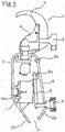
Fig. 1 den grundsätzlichen Aufbau einer Ausführungsvariante der Erfindung in einer Schrägansicht; -
Fig. 2 die Ausführungsvariante derFig. 1 in einer seitlichen Ansicht in geschlossenem Zustand; -
Fig. 3 eine Darstellung entsprechend derFig. 2 in geöffnetem Zustand. - Die erfindungsgemäße Vorrichtung besteht aus einem Haltekörper 1, der gleichzeitig ein Gehäuse bildet, an dem eine Klemme 2 angebracht ist, um die Vorrichtung an einer festen Struktur, beispielsweise einer Stange, zu befestigen. Die Klemme 2 besitzt einen gekrümmten Arm 3, der mit einer verstellbaren Zunge 4 zusammenwirkt, die durch eine Rändelschraube 5 betätigt werden kann, um die Vorrichtung an einer nicht dargestellten Stange festzulegen.
- Am Haltekörper 1 ist eine Andrückplatte 6 um eine Achse 6a schwenkbar gelagert. An dem der Achse 6a gegenüberliegenden Ende besitzt die Andrückplatte 6 einen abgewinkelten Endbereich 6b. Die Andrückplatte 6 wirkt mit einer Gegenplatte 7 zusammen, um eine Kluppe zu bilden, die zum Festhalten eines Vorhangs oder dergleichen dient. Dazu besitzt die Gegenplatte 7 ebenfalls einen abgewinkelten Endbereich 7b. Durch die Abwinkelung um etwa 45° wird erreicht, dass die beiden Endbereiche 6b, 7b einen Winkel von etwa 90° einschließen, was für die Befestigung des Vorhangs ideal ist.
- Die Betätigung der Andrückplatte 6 erfolgt durch eine Ankerplatte 8, die um eine Achse 8a schwenkbar gelagert ist und die mit der Andrückplatte 6 über ein einstellbares Verbindungselement 9 in der Form einer Rändelschraube verbunden ist. Elastomerelemente dienen zur Geräuschdämpfung zwischen Andrückplatte 6, Ankerplatte 8 und Verbindungselement 9.
- Der Abschnitt der Ankerplatte 8 zwischen der Lagerung 8a und dem Verbindungselement 9 ist als Angriffsfläche 8c ausgebildet, die mit dem Elektromagnet 10 zusammenwirkt.
- Die Andrückplatte 6 ist durch einen Elektromagnet 10 in die geschlossene Stellung der Kluppe spannbar, in welcher die Ankerplatte 8 idealerweise am Elektromagnet 10 anliegt oder minimal von diesem entfernt ist. Im angesteuerten Zustand hält der Elektromagnet 10 den Vorhang fest und gibt ihn frei, wenn die Ansteuerung beendet ist. Die Kluppe öffnet sich durch den Zug des Vorhangs 12 und gegebenenfalls durch das Eigengewicht der Andrückplatte 6, wenn die Vorrichtung etwas schräg zur Vertikalen montiert ist.
- Bei der Darstellung von
Fig. 2 ist beispielhaft ein Vorhang 12 von sehr geringer Dicke dargestellt, der zwischen den abgewickelten Endbereichen 6b, 7b der Andrückplatte 6 und der Gegenplatte 7 eingeklemmt ist. Sollte jedoch ein Vorhang 12 mit einer größeren Dicke zu halten sein, wird das Verbindungselement 9 so eingestellt, dass die Ankerplatte 8 im Wesentlichen die gleiche Stellung wie dargestellt einnimmt, während hingegen die Andrückplatte 6 entsprechend nach rechts (inFig. 2 ) ausgeschwenkt ist. - Bei der Darstellung in
Fig. 3 ist die Vorrichtung in geöffneter Darstellung gezeigt, in der ein ausreichend großer Freiraum 11 zwischen den abgewickelten Endbereichen 6b, 7b von Andrückplatte 6 und Gegenplatte 7 gegeben ist, um den Vorhang 12 fallen zu lassen. - Der Elektromagnet 10 wird elektrisch über einen Anschluss 13 versorgt, wobei bevorzugt ein Bus-System verwendet wird, um Stromversorgung und Auslösung voneinander zu entkoppeln. Auf diese Weise ist es möglich, mehrere erfindungsgemäße Vorrichtungen in serieller Weise einfach anzusteuern, wobei es dennoch aber möglich ist, jede einzelne Vorrichtung getrennt zu steuern.
Claims (7)
- Vorrichtung zum Aufhängen von Textilien, wie etwa Vorhängen, mit einem Haltekörper (1), der an einer festen Struktur befestigbar ist, einer am Haltekörper (1) fest angebrachten Gegenplatte (7), einer gelenkig am Haltekörper (1) befestigten Andrückplatte (6), wobei die Andrückplatte (6) mit der Gegenplatte (7) eine Kluppe zum Festhalten der Textilien bildet, und mit einem Elektromagnet (10), der mit einer Ankerplatte (8) zusammenwirkt, um die Kluppe zu schließen, dadurch gekennzeichnet, dass die Ankerplatte(8) am Haltekörper (1) gelagert ist und durch ein einstellbares Verbindungselement (9) mit der Andrückplatte (6) gekoppelt ist, und dass die Lagerung der Ankerplatte (8) am Haltekörper (1) zwischen der Lagerung der Andrückplatte (6) und dem einstellbaren Verbindungselement (9) angeordnet ist.
- Vorrichtung nach Anspruch 1, dadurch gekennzeichnet, dass in der geschlossenen Stellung der Kluppe ein Hauptabschnitt der Andrückplatte (6) und ein Hauptabschnitt der Ankerplatte (8) im Wesentlichen parallel zueinander angeordnet sind.
- Vorrichtung nach einem der Ansprüche 1 oder 2, dadurch gekennzeichnet, dass eine Angriffsfläche (8c) für den Elektromagnet (10) an der Ankerplatte (8) zwischen der Lagerung (8a) der Ankerplatte (8) und dem einstellbaren Verbindungselement (9) angeordnet ist.
- Vorrichtung nach einem der Ansprüche 1 bis 3, dadurch gekennzeichnet, dass der Haltekörper (1) einen U-förmigen Querschnitt aufweist und dass der Elektromagnet (10) darin aufgenommen ist.
- Vorrichtung nach einem der Ansprüche 1 bis 4, dadurch gekennzeichnet, dass die Andrückplatte (6) und die Gegenplatte (7) jeweils einen um etwa 45° abgewickelten Endbereich aufweisen.
- Vorrichtung nach einem der Ansprüche 1 bis 5, dadurch gekennzeichnet, dass das einstellbare Verbindungselement (9) auf Elastomeren gelagert ist.
- Vorrichtung nach einem der Ansprüche 1 bis 6, dadurch gekennzeichnet, dass der Abstand zwischen der Lagerung (8a) der Ankerplatte (8) und dem einstellbaren Verbindungselement (9) zwischen 50% und 80% des Abstands zwischen der Lagerung (6a) der Andrückplatte (6) und dem einstellbaren Verbindungselement (9) beträgt.
Priority Applications (1)
| Application Number | Priority Date | Filing Date | Title |
|---|---|---|---|
| PL15158588T PL2918322T3 (pl) | 2014-03-11 | 2015-03-11 | Urządzenie do zawieszania tekstyliów |
Applications Claiming Priority (1)
| Application Number | Priority Date | Filing Date | Title |
|---|---|---|---|
| ATA50176/2014A AT515457B1 (de) | 2014-03-11 | 2014-03-11 | Vorrichtung zum Aufhängen von Textilien |
Publications (2)
| Publication Number | Publication Date |
|---|---|
| EP2918322A1 EP2918322A1 (de) | 2015-09-16 |
| EP2918322B1 true EP2918322B1 (de) | 2017-01-04 |
Family
ID=53015481
Family Applications (1)
| Application Number | Title | Priority Date | Filing Date |
|---|---|---|---|
| EP15158588.2A Active EP2918322B1 (de) | 2014-03-11 | 2015-03-11 | Vorrichtung zum aufhängen von textilien |
Country Status (4)
| Country | Link |
|---|---|
| US (1) | US9510703B2 (de) |
| EP (1) | EP2918322B1 (de) |
| AT (2) | AT515457B1 (de) |
| PL (1) | PL2918322T3 (de) |
Families Citing this family (1)
| Publication number | Priority date | Publication date | Assignee | Title |
|---|---|---|---|---|
| EP3235462B1 (de) * | 2011-02-15 | 2019-04-24 | Brainlab AG | Referenzanordnungsverbinderanordnung zum festklemmen eines op-tuches |
Family Cites Families (24)
| Publication number | Priority date | Publication date | Assignee | Title |
|---|---|---|---|---|
| US996886A (en) * | 1910-12-05 | 1911-07-04 | Bruno Schneider | Combined curtain-pole ring and clamp. |
| US1213569A (en) * | 1914-08-14 | 1917-01-23 | George Wordingham | Swivel-hook for coat-hangers. |
| CH348001A (de) * | 1957-01-05 | 1960-07-31 | Buehlmann Josef | Gatter zur Trennung von Mutterschweinen von den Ferkeln innerhalb des Stallpferches |
| GB962931A (en) * | 1962-05-18 | 1964-07-08 | Vitamins Ltd | Improvements in or relating to pig production pens |
| DE1607119A1 (de) * | 1966-03-16 | 1970-08-13 | Erich Dietze & Co | Abferkelbucht |
| SE445872B (sv) * | 1985-05-17 | 1986-07-28 | Andersson Karl Arne | Anleggning for smagrisproduktion |
| DE9203631U1 (de) * | 1992-03-18 | 1992-05-27 | Mannebeck, Bernhard, 4443 Quendorf | Abferkelbucht |
| DE29906503U1 (de) * | 1999-04-13 | 1999-08-12 | Werkmann, Ulrich, 60386 Frankfurt | Magnet Kabuki System |
| JP2001120311A (ja) * | 1999-10-27 | 2001-05-08 | Ykk Corp | 係着具 |
| AU762176B2 (en) * | 1999-12-14 | 2003-06-19 | Hunter Douglas Industries Bv | Holder for a depending hollow architectural covering |
| US6484788B1 (en) * | 2000-03-30 | 2002-11-26 | Town & Country Living | Self-locking curtain clip |
| US7007428B2 (en) * | 2001-01-18 | 2006-03-07 | Santa Cruz Cathy D | Vertical telescopic stage accessories device |
| DE20207558U1 (de) * | 2002-05-10 | 2002-08-29 | HERMES Stalleinrichtungen GmbH Werk II, 09557 Flöha | Abferkelbucht für die tiergerechte Schweinehaltung |
| BE1015046A6 (nl) * | 2002-07-19 | 2004-09-07 | Kerkhoven Koen Van | Inrichting voor het laten vallen van een gordijn. |
| DE202004002751U1 (de) * | 2004-02-21 | 2004-08-26 | Lammers Systemtechnik Gmbh & Co. Kg | Abferkelbucht mit einem Sauenkäfig |
| US7509992B2 (en) * | 2006-04-07 | 2009-03-31 | Fragoso Jesus Chuy | Kabuki stage setting release device |
| DE102007015313B4 (de) * | 2007-03-28 | 2009-03-19 | Gerriets Gmbh | Vorrichtung zum plötzlichen Abwerfen von Vorhängen und sonstigen Dekorationen in der Bühnen- und Veranstaltungstechnik |
| US8240489B2 (en) * | 2009-09-17 | 2012-08-14 | Selective Enterprises, Inc. | Traverse rod assembly |
| US8181924B2 (en) * | 2009-12-09 | 2012-05-22 | Daniel Pepe | Magnetic textile hanger |
| US8307499B2 (en) * | 2010-12-09 | 2012-11-13 | Fabian Ruffo | Hanger for window drape and slide assembly including hanger |
| US20130092329A1 (en) * | 2011-10-13 | 2013-04-18 | All Access Staging & Productions, Inc. | Curtain sniffer |
| CN202312774U (zh) * | 2011-11-25 | 2012-07-11 | 李源 | 幕式遮光窗帘 |
| AT513138B1 (de) * | 2012-08-14 | 2014-02-15 | Schauer Agrotronic Gmbh | Einzelabferkelbucht |
| DE202014100501U1 (de) * | 2014-02-05 | 2014-02-27 | Erwin Weihmüller GmbH & Co. Stalltechnik KG | Abferkelbucht |
-
2014
- 2014-03-11 AT ATA50176/2014A patent/AT515457B1/de not_active IP Right Cessation
- 2014-10-31 AT ATA8017/2015A patent/AT516402B1/de active
-
2015
- 2015-03-11 US US14/644,807 patent/US9510703B2/en not_active Expired - Fee Related
- 2015-03-11 EP EP15158588.2A patent/EP2918322B1/de active Active
- 2015-03-11 PL PL15158588T patent/PL2918322T3/pl unknown
Non-Patent Citations (1)
| Title |
|---|
| None * |
Also Published As
| Publication number | Publication date |
|---|---|
| PL2918322T3 (pl) | 2017-07-31 |
| EP2918322A1 (de) | 2015-09-16 |
| AT515457B1 (de) | 2016-02-15 |
| AT516402A4 (de) | 2016-05-15 |
| AT516402B1 (de) | 2016-05-15 |
| US9510703B2 (en) | 2016-12-06 |
| US20150257570A1 (en) | 2015-09-17 |
| AT515457A1 (de) | 2015-09-15 |
Similar Documents
| Publication | Publication Date | Title |
|---|---|---|
| DE102010060722B4 (de) | Verbindungsbeschlag | |
| EP2956274B1 (de) | Lösbare blockiervorrichtung insbesondere an einem spannwerkzeug | |
| DE202004014219U1 (de) | Befestigungselement | |
| DE112005000915T5 (de) | Eine Vorrichtung zum Umklappen von Auto-Kopfstützen | |
| WO2009076785A1 (de) | Vorrichtung zum einziehen und dämpfen einer in einer profilschiene zum führen von laufwerken getragenen schiebetür in die endlage | |
| DE102007013438B4 (de) | Blumenkastenhalterung mit einer Klemmvorrichtung | |
| DE102008022675B3 (de) | Gurtschloss für ein Sicherheitsgurtsystem | |
| DE112014005467T5 (de) | Haltevorrichtung für Fahrzeugkopfstützen | |
| EP2579402B1 (de) | Befestigungsvorrichtung zum Befestigen eines Installationsgeräts an einer Tragschiene | |
| EP3001931A1 (de) | Blendenprofilabdeckvorrichtung | |
| EP3540165B1 (de) | Vorrichtung und verfahren zur befestigung von zargen | |
| EP2918322B1 (de) | Vorrichtung zum aufhängen von textilien | |
| WO2013120643A1 (de) | Klemmbefestigung zur befestigung eines gehäuses an einer schiene | |
| DE102013100575B3 (de) | Befestigungsvorrichtung für einen Rückhaltegurt | |
| DE102012110208B4 (de) | Betätigungseinheit für einen Fahrzeugsitz | |
| EP1617037B1 (de) | Vorrichtung zum Befestigen einer Store sowie ein dazu geeigneter Haltebügel | |
| DE102012007771C5 (de) | Montageplattenhalter für einen Schaltschrank sowie ein Befestigungsmittel zur Verwendung bei diesem | |
| DE102010019685B4 (de) | Vorrichtung zum Einhängen von Gegenständen | |
| DE102013215232A1 (de) | Vorrichtung zur Befestigung eines Fahrgastsitzes in einem Verkehrsmittel | |
| AT516730B1 (de) | Befestigungsvorrichtung für eine Frontblende sowie damit ausgestattetes Möbelstück | |
| EP1843680B1 (de) | Schubkasten mit zwei seitenzargen und mit einer blende | |
| DE10348436B4 (de) | Gestänge für einen Türschließer oder dergleichen | |
| DE112011104806B4 (de) | Verbindungsbeschlag | |
| DE102016113171A1 (de) | Halterung zur Befestigung eines Objekts, bevorzugt einer Sonnen- und/oder Blickschutzvorrichtung, besonders bevorzugt einer Seilhalterung der Sonnen- und/oder Blickschutzvorrichtung, an einem Fenster- oder Türrahmen und Verwendung einer Halterung zur Befestigung eines Objekts an einem Fenster- oder Türrahmen, insbesondere Verwendung einer erfindungsgemäßen Halterung | |
| DE202015103140U1 (de) | Verstelleinrichtung für die vertikale und die horizontale Verstellung einer Frontblende an einem Schub, Schublade oder dergleichen |
Legal Events
| Date | Code | Title | Description |
|---|---|---|---|
| PUAI | Public reference made under article 153(3) epc to a published international application that has entered the european phase |
Free format text: ORIGINAL CODE: 0009012 |
|
| AK | Designated contracting states |
Kind code of ref document: A1 Designated state(s): AL AT BE BG CH CY CZ DE DK EE ES FI FR GB GR HR HU IE IS IT LI LT LU LV MC MK MT NL NO PL PT RO RS SE SI SK SM TR |
|
| AX | Request for extension of the european patent |
Extension state: BA ME |
|
| 17P | Request for examination filed |
Effective date: 20160225 |
|
| RBV | Designated contracting states (corrected) |
Designated state(s): AL AT BE BG CH CY CZ DE DK EE ES FI FR GB GR HR HU IE IS IT LI LT LU LV MC MK MT NL NO PL PT RO RS SE SI SK SM TR |
|
| GRAP | Despatch of communication of intention to grant a patent |
Free format text: ORIGINAL CODE: EPIDOSNIGR1 |
|
| INTG | Intention to grant announced |
Effective date: 20160812 |
|
| GRAS | Grant fee paid |
Free format text: ORIGINAL CODE: EPIDOSNIGR3 |
|
| GRAA | (expected) grant |
Free format text: ORIGINAL CODE: 0009210 |
|
| AK | Designated contracting states |
Kind code of ref document: B1 Designated state(s): AL AT BE BG CH CY CZ DE DK EE ES FI FR GB GR HR HU IE IS IT LI LT LU LV MC MK MT NL NO PL PT RO RS SE SI SK SM TR |
|
| REG | Reference to a national code |
Ref country code: GB Ref legal event code: FG4D Free format text: NOT ENGLISH |
|
| REG | Reference to a national code |
Ref country code: CH Ref legal event code: EP |
|
| REG | Reference to a national code |
Ref country code: AT Ref legal event code: REF Ref document number: 858674 Country of ref document: AT Kind code of ref document: T Effective date: 20170115 |
|
| REG | Reference to a national code |
Ref country code: IE Ref legal event code: FG4D Free format text: LANGUAGE OF EP DOCUMENT: GERMAN |
|
| REG | Reference to a national code |
Ref country code: DE Ref legal event code: R096 Ref document number: 502015000458 Country of ref document: DE |
|
| REG | Reference to a national code |
Ref country code: FR Ref legal event code: PLFP Year of fee payment: 3 |
|
| REG | Reference to a national code |
Ref country code: LT Ref legal event code: MG4D Ref country code: NL Ref legal event code: MP Effective date: 20170104 |
|
| PG25 | Lapsed in a contracting state [announced via postgrant information from national office to epo] |
Ref country code: NL Free format text: LAPSE BECAUSE OF FAILURE TO SUBMIT A TRANSLATION OF THE DESCRIPTION OR TO PAY THE FEE WITHIN THE PRESCRIBED TIME-LIMIT Effective date: 20170104 |
|
| PG25 | Lapsed in a contracting state [announced via postgrant information from national office to epo] |
Ref country code: LT Free format text: LAPSE BECAUSE OF FAILURE TO SUBMIT A TRANSLATION OF THE DESCRIPTION OR TO PAY THE FEE WITHIN THE PRESCRIBED TIME-LIMIT Effective date: 20170104 Ref country code: HR Free format text: LAPSE BECAUSE OF FAILURE TO SUBMIT A TRANSLATION OF THE DESCRIPTION OR TO PAY THE FEE WITHIN THE PRESCRIBED TIME-LIMIT Effective date: 20170104 Ref country code: GR Free format text: LAPSE BECAUSE OF FAILURE TO SUBMIT A TRANSLATION OF THE DESCRIPTION OR TO PAY THE FEE WITHIN THE PRESCRIBED TIME-LIMIT Effective date: 20170405 Ref country code: NO Free format text: LAPSE BECAUSE OF FAILURE TO SUBMIT A TRANSLATION OF THE DESCRIPTION OR TO PAY THE FEE WITHIN THE PRESCRIBED TIME-LIMIT Effective date: 20170404 Ref country code: FI Free format text: LAPSE BECAUSE OF FAILURE TO SUBMIT A TRANSLATION OF THE DESCRIPTION OR TO PAY THE FEE WITHIN THE PRESCRIBED TIME-LIMIT Effective date: 20170104 Ref country code: IS Free format text: LAPSE BECAUSE OF FAILURE TO SUBMIT A TRANSLATION OF THE DESCRIPTION OR TO PAY THE FEE WITHIN THE PRESCRIBED TIME-LIMIT Effective date: 20170504 |
|
| PG25 | Lapsed in a contracting state [announced via postgrant information from national office to epo] |
Ref country code: BG Free format text: LAPSE BECAUSE OF FAILURE TO SUBMIT A TRANSLATION OF THE DESCRIPTION OR TO PAY THE FEE WITHIN THE PRESCRIBED TIME-LIMIT Effective date: 20170404 Ref country code: PT Free format text: LAPSE BECAUSE OF FAILURE TO SUBMIT A TRANSLATION OF THE DESCRIPTION OR TO PAY THE FEE WITHIN THE PRESCRIBED TIME-LIMIT Effective date: 20170504 Ref country code: ES Free format text: LAPSE BECAUSE OF FAILURE TO SUBMIT A TRANSLATION OF THE DESCRIPTION OR TO PAY THE FEE WITHIN THE PRESCRIBED TIME-LIMIT Effective date: 20170104 Ref country code: SE Free format text: LAPSE BECAUSE OF FAILURE TO SUBMIT A TRANSLATION OF THE DESCRIPTION OR TO PAY THE FEE WITHIN THE PRESCRIBED TIME-LIMIT Effective date: 20170104 Ref country code: LV Free format text: LAPSE BECAUSE OF FAILURE TO SUBMIT A TRANSLATION OF THE DESCRIPTION OR TO PAY THE FEE WITHIN THE PRESCRIBED TIME-LIMIT Effective date: 20170104 Ref country code: RS Free format text: LAPSE BECAUSE OF FAILURE TO SUBMIT A TRANSLATION OF THE DESCRIPTION OR TO PAY THE FEE WITHIN THE PRESCRIBED TIME-LIMIT Effective date: 20170104 |
|
| REG | Reference to a national code |
Ref country code: DE Ref legal event code: R097 Ref document number: 502015000458 Country of ref document: DE |
|
| PG25 | Lapsed in a contracting state [announced via postgrant information from national office to epo] |
Ref country code: CZ Free format text: LAPSE BECAUSE OF FAILURE TO SUBMIT A TRANSLATION OF THE DESCRIPTION OR TO PAY THE FEE WITHIN THE PRESCRIBED TIME-LIMIT Effective date: 20170104 Ref country code: IT Free format text: LAPSE BECAUSE OF FAILURE TO SUBMIT A TRANSLATION OF THE DESCRIPTION OR TO PAY THE FEE WITHIN THE PRESCRIBED TIME-LIMIT Effective date: 20170104 Ref country code: SK Free format text: LAPSE BECAUSE OF FAILURE TO SUBMIT A TRANSLATION OF THE DESCRIPTION OR TO PAY THE FEE WITHIN THE PRESCRIBED TIME-LIMIT Effective date: 20170104 Ref country code: EE Free format text: LAPSE BECAUSE OF FAILURE TO SUBMIT A TRANSLATION OF THE DESCRIPTION OR TO PAY THE FEE WITHIN THE PRESCRIBED TIME-LIMIT Effective date: 20170104 Ref country code: RO Free format text: LAPSE BECAUSE OF FAILURE TO SUBMIT A TRANSLATION OF THE DESCRIPTION OR TO PAY THE FEE WITHIN THE PRESCRIBED TIME-LIMIT Effective date: 20170104 |
|
| PLBE | No opposition filed within time limit |
Free format text: ORIGINAL CODE: 0009261 |
|
| STAA | Information on the status of an ep patent application or granted ep patent |
Free format text: STATUS: NO OPPOSITION FILED WITHIN TIME LIMIT |
|
| PG25 | Lapsed in a contracting state [announced via postgrant information from national office to epo] |
Ref country code: DK Free format text: LAPSE BECAUSE OF FAILURE TO SUBMIT A TRANSLATION OF THE DESCRIPTION OR TO PAY THE FEE WITHIN THE PRESCRIBED TIME-LIMIT Effective date: 20170104 Ref country code: SM Free format text: LAPSE BECAUSE OF FAILURE TO SUBMIT A TRANSLATION OF THE DESCRIPTION OR TO PAY THE FEE WITHIN THE PRESCRIBED TIME-LIMIT Effective date: 20170104 Ref country code: MC Free format text: LAPSE BECAUSE OF FAILURE TO SUBMIT A TRANSLATION OF THE DESCRIPTION OR TO PAY THE FEE WITHIN THE PRESCRIBED TIME-LIMIT Effective date: 20170104 |
|
| REG | Reference to a national code |
Ref country code: IE Ref legal event code: MM4A |
|
| PG25 | Lapsed in a contracting state [announced via postgrant information from national office to epo] |
Ref country code: LU Free format text: LAPSE BECAUSE OF NON-PAYMENT OF DUE FEES Effective date: 20170311 |
|
| PG25 | Lapsed in a contracting state [announced via postgrant information from national office to epo] |
Ref country code: SI Free format text: LAPSE BECAUSE OF FAILURE TO SUBMIT A TRANSLATION OF THE DESCRIPTION OR TO PAY THE FEE WITHIN THE PRESCRIBED TIME-LIMIT Effective date: 20170104 Ref country code: IE Free format text: LAPSE BECAUSE OF NON-PAYMENT OF DUE FEES Effective date: 20170311 |
|
| REG | Reference to a national code |
Ref country code: BE Ref legal event code: MM Effective date: 20170331 |
|
| REG | Reference to a national code |
Ref country code: FR Ref legal event code: PLFP Year of fee payment: 4 |
|
| PG25 | Lapsed in a contracting state [announced via postgrant information from national office to epo] |
Ref country code: BE Free format text: LAPSE BECAUSE OF NON-PAYMENT OF DUE FEES Effective date: 20170331 |
|
| PG25 | Lapsed in a contracting state [announced via postgrant information from national office to epo] |
Ref country code: MT Free format text: LAPSE BECAUSE OF FAILURE TO SUBMIT A TRANSLATION OF THE DESCRIPTION OR TO PAY THE FEE WITHIN THE PRESCRIBED TIME-LIMIT Effective date: 20170104 |
|
| REG | Reference to a national code |
Ref country code: CH Ref legal event code: PL |
|
| PG25 | Lapsed in a contracting state [announced via postgrant information from national office to epo] |
Ref country code: CH Free format text: LAPSE BECAUSE OF NON-PAYMENT OF DUE FEES Effective date: 20180331 Ref country code: LI Free format text: LAPSE BECAUSE OF NON-PAYMENT OF DUE FEES Effective date: 20180331 |
|
| PG25 | Lapsed in a contracting state [announced via postgrant information from national office to epo] |
Ref country code: HU Free format text: LAPSE BECAUSE OF FAILURE TO SUBMIT A TRANSLATION OF THE DESCRIPTION OR TO PAY THE FEE WITHIN THE PRESCRIBED TIME-LIMIT; INVALID AB INITIO Effective date: 20150311 |
|
| PG25 | Lapsed in a contracting state [announced via postgrant information from national office to epo] |
Ref country code: CY Free format text: LAPSE BECAUSE OF FAILURE TO SUBMIT A TRANSLATION OF THE DESCRIPTION OR TO PAY THE FEE WITHIN THE PRESCRIBED TIME-LIMIT Effective date: 20170104 |
|
| PG25 | Lapsed in a contracting state [announced via postgrant information from national office to epo] |
Ref country code: MK Free format text: LAPSE BECAUSE OF FAILURE TO SUBMIT A TRANSLATION OF THE DESCRIPTION OR TO PAY THE FEE WITHIN THE PRESCRIBED TIME-LIMIT Effective date: 20170104 |
|
| PG25 | Lapsed in a contracting state [announced via postgrant information from national office to epo] |
Ref country code: TR Free format text: LAPSE BECAUSE OF FAILURE TO SUBMIT A TRANSLATION OF THE DESCRIPTION OR TO PAY THE FEE WITHIN THE PRESCRIBED TIME-LIMIT Effective date: 20170104 |
|
| PG25 | Lapsed in a contracting state [announced via postgrant information from national office to epo] |
Ref country code: AL Free format text: LAPSE BECAUSE OF FAILURE TO SUBMIT A TRANSLATION OF THE DESCRIPTION OR TO PAY THE FEE WITHIN THE PRESCRIBED TIME-LIMIT Effective date: 20170104 |
|
| PGFP | Annual fee paid to national office [announced via postgrant information from national office to epo] |
Ref country code: AT Payment date: 20220301 Year of fee payment: 8 |
|
| PGFP | Annual fee paid to national office [announced via postgrant information from national office to epo] |
Ref country code: FR Payment date: 20230324 Year of fee payment: 9 |
|
| PGFP | Annual fee paid to national office [announced via postgrant information from national office to epo] |
Ref country code: GB Payment date: 20230322 Year of fee payment: 9 |
|
| REG | Reference to a national code |
Ref country code: AT Ref legal event code: MM01 Ref document number: 858674 Country of ref document: AT Kind code of ref document: T Effective date: 20230311 |
|
| PG25 | Lapsed in a contracting state [announced via postgrant information from national office to epo] |
Ref country code: AT Free format text: LAPSE BECAUSE OF NON-PAYMENT OF DUE FEES Effective date: 20230311 |
|
| GBPC | Gb: european patent ceased through non-payment of renewal fee |
Effective date: 20240311 |
|
| PGFP | Annual fee paid to national office [announced via postgrant information from national office to epo] |
Ref country code: PL Payment date: 20241231 Year of fee payment: 11 |
|
| PG25 | Lapsed in a contracting state [announced via postgrant information from national office to epo] |
Ref country code: GB Free format text: LAPSE BECAUSE OF NON-PAYMENT OF DUE FEES Effective date: 20240311 |
|
| PG25 | Lapsed in a contracting state [announced via postgrant information from national office to epo] |
Ref country code: FR Free format text: LAPSE BECAUSE OF NON-PAYMENT OF DUE FEES Effective date: 20240331 |
|
| PG25 | Lapsed in a contracting state [announced via postgrant information from national office to epo] |
Ref country code: GB Free format text: LAPSE BECAUSE OF NON-PAYMENT OF DUE FEES Effective date: 20240311 Ref country code: FR Free format text: LAPSE BECAUSE OF NON-PAYMENT OF DUE FEES Effective date: 20240331 |
|
| PGFP | Annual fee paid to national office [announced via postgrant information from national office to epo] |
Ref country code: DE Payment date: 20260304 Year of fee payment: 12 |