EP2918399A1 - Verfahren zur Herstellung eines Windturbinenrotorblatts - Google Patents
Verfahren zur Herstellung eines Windturbinenrotorblatts Download PDFInfo
- Publication number
- EP2918399A1 EP2918399A1 EP14158529.9A EP14158529A EP2918399A1 EP 2918399 A1 EP2918399 A1 EP 2918399A1 EP 14158529 A EP14158529 A EP 14158529A EP 2918399 A1 EP2918399 A1 EP 2918399A1
- Authority
- EP
- European Patent Office
- Prior art keywords
- core member
- layup
- mold
- fiber material
- rotor blade
- Prior art date
- Legal status (The legal status is an assumption and is not a legal conclusion. Google has not performed a legal analysis and makes no representation as to the accuracy of the status listed.)
- Granted
Links
Images
Classifications
-
- B—PERFORMING OPERATIONS; TRANSPORTING
- B29—WORKING OF PLASTICS; WORKING OF SUBSTANCES IN A PLASTIC STATE IN GENERAL
- B29C—SHAPING OR JOINING OF PLASTICS; SHAPING OF MATERIAL IN A PLASTIC STATE, NOT OTHERWISE PROVIDED FOR; AFTER-TREATMENT OF THE SHAPED PRODUCTS, e.g. REPAIRING
- B29C70/00—Shaping composites, i.e. plastics material comprising reinforcements, fillers or preformed parts, e.g. inserts
- B29C70/04—Shaping composites, i.e. plastics material comprising reinforcements, fillers or preformed parts, e.g. inserts comprising reinforcements only, e.g. self-reinforcing plastics
- B29C70/28—Shaping operations therefor
- B29C70/30—Shaping by lay-up, i.e. applying fibres, tape or broadsheet on a mould, former or core; Shaping by spray-up, i.e. spraying of fibres on a mould, former or core
- B29C70/34—Shaping by lay-up, i.e. applying fibres, tape or broadsheet on a mould, former or core; Shaping by spray-up, i.e. spraying of fibres on a mould, former or core and shaping or impregnating by compression, i.e. combined with compressing after the lay-up operation
-
- B—PERFORMING OPERATIONS; TRANSPORTING
- B29—WORKING OF PLASTICS; WORKING OF SUBSTANCES IN A PLASTIC STATE IN GENERAL
- B29C—SHAPING OR JOINING OF PLASTICS; SHAPING OF MATERIAL IN A PLASTIC STATE, NOT OTHERWISE PROVIDED FOR; AFTER-TREATMENT OF THE SHAPED PRODUCTS, e.g. REPAIRING
- B29C70/00—Shaping composites, i.e. plastics material comprising reinforcements, fillers or preformed parts, e.g. inserts
- B29C70/04—Shaping composites, i.e. plastics material comprising reinforcements, fillers or preformed parts, e.g. inserts comprising reinforcements only, e.g. self-reinforcing plastics
- B29C70/28—Shaping operations therefor
- B29C70/40—Shaping or impregnating by compression not applied
- B29C70/42—Shaping or impregnating by compression not applied for producing articles of definite length, i.e. discrete articles
- B29C70/46—Shaping or impregnating by compression not applied for producing articles of definite length, i.e. discrete articles using matched moulds, e.g. for deforming sheet moulding compounds [SMC] or prepregs
-
- B—PERFORMING OPERATIONS; TRANSPORTING
- B29—WORKING OF PLASTICS; WORKING OF SUBSTANCES IN A PLASTIC STATE IN GENERAL
- B29C—SHAPING OR JOINING OF PLASTICS; SHAPING OF MATERIAL IN A PLASTIC STATE, NOT OTHERWISE PROVIDED FOR; AFTER-TREATMENT OF THE SHAPED PRODUCTS, e.g. REPAIRING
- B29C33/00—Moulds or cores; Details thereof or accessories therefor
- B29C33/0011—Moulds or cores; Details thereof or accessories therefor thin-walled moulds
- B29C33/0016—Lost moulds, e.g. staying on the moulded object
-
- B—PERFORMING OPERATIONS; TRANSPORTING
- B29—WORKING OF PLASTICS; WORKING OF SUBSTANCES IN A PLASTIC STATE IN GENERAL
- B29C—SHAPING OR JOINING OF PLASTICS; SHAPING OF MATERIAL IN A PLASTIC STATE, NOT OTHERWISE PROVIDED FOR; AFTER-TREATMENT OF THE SHAPED PRODUCTS, e.g. REPAIRING
- B29C70/00—Shaping composites, i.e. plastics material comprising reinforcements, fillers or preformed parts, e.g. inserts
- B29C70/04—Shaping composites, i.e. plastics material comprising reinforcements, fillers or preformed parts, e.g. inserts comprising reinforcements only, e.g. self-reinforcing plastics
- B29C70/28—Shaping operations therefor
- B29C70/30—Shaping by lay-up, i.e. applying fibres, tape or broadsheet on a mould, former or core; Shaping by spray-up, i.e. spraying of fibres on a mould, former or core
- B29C70/34—Shaping by lay-up, i.e. applying fibres, tape or broadsheet on a mould, former or core; Shaping by spray-up, i.e. spraying of fibres on a mould, former or core and shaping or impregnating by compression, i.e. combined with compressing after the lay-up operation
- B29C70/342—Shaping by lay-up, i.e. applying fibres, tape or broadsheet on a mould, former or core; Shaping by spray-up, i.e. spraying of fibres on a mould, former or core and shaping or impregnating by compression, i.e. combined with compressing after the lay-up operation using isostatic pressure
-
- B—PERFORMING OPERATIONS; TRANSPORTING
- B29—WORKING OF PLASTICS; WORKING OF SUBSTANCES IN A PLASTIC STATE IN GENERAL
- B29D—PRODUCING PARTICULAR ARTICLES FROM PLASTICS OR FROM SUBSTANCES IN A PLASTIC STATE
- B29D99/00—Subject matter not provided for in other groups of this subclass
- B29D99/0025—Producing blades or the like, e.g. blades for turbines, propellers, or wings
-
- B—PERFORMING OPERATIONS; TRANSPORTING
- B29—WORKING OF PLASTICS; WORKING OF SUBSTANCES IN A PLASTIC STATE IN GENERAL
- B29C—SHAPING OR JOINING OF PLASTICS; SHAPING OF MATERIAL IN A PLASTIC STATE, NOT OTHERWISE PROVIDED FOR; AFTER-TREATMENT OF THE SHAPED PRODUCTS, e.g. REPAIRING
- B29C33/00—Moulds or cores; Details thereof or accessories therefor
- B29C33/76—Cores
-
- B—PERFORMING OPERATIONS; TRANSPORTING
- B29—WORKING OF PLASTICS; WORKING OF SUBSTANCES IN A PLASTIC STATE IN GENERAL
- B29L—INDEXING SCHEME ASSOCIATED WITH SUBCLASS B29C, RELATING TO PARTICULAR ARTICLES
- B29L2031/00—Other particular articles
- B29L2031/08—Blades for rotors, stators, fans, turbines or the like, e.g. screw propellers
- B29L2031/082—Blades, e.g. for helicopters
- B29L2031/085—Wind turbine blades
-
- Y—GENERAL TAGGING OF NEW TECHNOLOGICAL DEVELOPMENTS; GENERAL TAGGING OF CROSS-SECTIONAL TECHNOLOGIES SPANNING OVER SEVERAL SECTIONS OF THE IPC; TECHNICAL SUBJECTS COVERED BY FORMER USPC CROSS-REFERENCE ART COLLECTIONS [XRACs] AND DIGESTS
- Y02—TECHNOLOGIES OR APPLICATIONS FOR MITIGATION OR ADAPTATION AGAINST CLIMATE CHANGE
- Y02E—REDUCTION OF GREENHOUSE GAS [GHG] EMISSIONS, RELATED TO ENERGY GENERATION, TRANSMISSION OR DISTRIBUTION
- Y02E10/00—Energy generation through renewable energy sources
- Y02E10/70—Wind energy
- Y02E10/72—Wind turbines with rotation axis in wind direction
-
- Y—GENERAL TAGGING OF NEW TECHNOLOGICAL DEVELOPMENTS; GENERAL TAGGING OF CROSS-SECTIONAL TECHNOLOGIES SPANNING OVER SEVERAL SECTIONS OF THE IPC; TECHNICAL SUBJECTS COVERED BY FORMER USPC CROSS-REFERENCE ART COLLECTIONS [XRACs] AND DIGESTS
- Y02—TECHNOLOGIES OR APPLICATIONS FOR MITIGATION OR ADAPTATION AGAINST CLIMATE CHANGE
- Y02P—CLIMATE CHANGE MITIGATION TECHNOLOGIES IN THE PRODUCTION OR PROCESSING OF GOODS
- Y02P70/00—Climate change mitigation technologies in the production process for final industrial or consumer products
- Y02P70/50—Manufacturing or production processes characterised by the final manufactured product
-
- Y—GENERAL TAGGING OF NEW TECHNOLOGICAL DEVELOPMENTS; GENERAL TAGGING OF CROSS-SECTIONAL TECHNOLOGIES SPANNING OVER SEVERAL SECTIONS OF THE IPC; TECHNICAL SUBJECTS COVERED BY FORMER USPC CROSS-REFERENCE ART COLLECTIONS [XRACs] AND DIGESTS
- Y10—TECHNICAL SUBJECTS COVERED BY FORMER USPC
- Y10T—TECHNICAL SUBJECTS COVERED BY FORMER US CLASSIFICATION
- Y10T156/00—Adhesive bonding and miscellaneous chemical manufacture
- Y10T156/10—Methods of surface bonding and/or assembly therefor
- Y10T156/1002—Methods of surface bonding and/or assembly therefor with permanent bending or reshaping or surface deformation of self sustaining lamina
Definitions
- the present invention relates to a method for manufacturing a rotor blade for a wind turbine.
- Modern wind turbine rotor blades are built from fiber-reinforced composites combined with core members, such as balsa wood or plastic foam.
- EP 2 123 431 A1 describes a method for manufacturing a rotor blade using a vacuum assisted resin transfer molding (VARTM)-process.
- VARTM vacuum assisted resin transfer molding
- fiber material is laid onto a lower part and an upper part of a mold, respectively.
- the fiber material is secured in place by vacuum applied from beneath.
- mold cores are covered in vacuum bags and are placed in the lower part of the mold together with a web (also known as shear web).
- the upper part of the mold, together with the fiber material is turned 180 degrees about its longitudinal axis and put into place so that the mold is closed.
- vacuum is applied to the space between the mold cores and the mold.
- resin is injected. When the resin has set, the mold cores are removed, the mold is opened and the cured blade is removed from the mold.
- the webs typically employed in the process are manufactured in a separate process. According to said separate process, plywood plates are covered with a fiber material. The fiber material is injected with a resin. Once the resin has set, the cured web comprising a fiber reinforced resin and a plywood core can be taken out of a corresponding mold.
- the webs are required to have a recess at one end.
- the recess is configured to ensure a smooth transfer of loads into and out of the rotor blade, i.e. the recess avoids stress concentrations due to abrupt changes in the geometry.
- the recess is machined into said end of the web. In this process about 60 - 100 kg of web material need to be removed which requires substantial manpower and causes waste.
- One objective of the present invention is to provide an improved method for manufacturing a rotor blade for a wind turbine.
- a method for manufacturing a rotor blade for a wind turbine comprises: arranging a first layup of fiber material inside a mold, the first layup corresponding to an airfoil of the rotor blade, b) arranging a second layup of fiber material on a core member before and/or after arranging the core member in the mold, the second layup including the core member corresponding to a web of the rotor blade, the core member comprising a recess configured to ensure a smooth transfer of loads into and out of the web, and c) curing a resin impregnating the fiber material of the first and second layup to form the rotor blade.
- the method is advantageous in that there is no need anymore to machine the recess into the cured web, thus saving man power and avoiding waste. Rather, the recess is provided in the core member, and the dry or wetted (i.e. impregnated with resin) and therefore flexible second fiber layup is provided so as to follow the geometry of the recess.
- the core member may be comprised of wood or plastic foam, e.g. polyvinyl chloride (PVC), polyethylene terephthalate (PET), polybutylene terephthalate (PBT) or polyurethane (PU). Both materials may easily be provided with the recess.
- the core member may be machined, in particular sawed, to have the required shape. Or, in the case of foam in particular, the core member may be cast in the desired shape having the recess.
- the core member may comprise of a plurality of core elements which can be connected in manner to form the desired shape.
- the fiber material used for the first and second layup may comprise fiber material of different shapes and composition.
- the fiber material may comprise a layup of fibers, rovings, a fiber mat, a fiber fabric, woven fibers or a fiber felt.
- the fibers may be arranged unidirectionally, in a biax-configuration or in any other configuration.
- the fibers may comprise glass fibers, carbon fibers and/or aramid fibers, for example.
- the fiber material may be supplied in a pre-impregnated state (so called prepreg material) or in an unimpregnated state. In the latter case, the fiber material is impregnated with a resin before step (c).
- the resin may be injected into the fiber material in a resin transfer molding (RTM) or vacuum-assisted resin transfer molding (VARTM)-process.
- RTM resin transfer molding
- VARTM vacuum-assisted resin transfer molding
- the first and second layup comprising the fiber material as well as the core member are covered in a vacuum bag.
- vacuum is applied to the region between the vacuum bag and the mold.
- resin is injected in said region.
- the vacuum bag and/or the mold is removed and the final rotor blade is obtained.
- the prepreg material there is no need to inject the fibers material with resin.
- the mold may be an open or a closed mold.
- the mold may comprise one or more parts, in particular a lower part and an upper part.
- Uncured herein refers to the resin not being hardened and/or cross-linked at all or not to a substantial extent.
- Cured or “set” refers to the resin being hardened and/or cross-linked to an extent where a shape of the fiber-reinforced resin will not or not significantly change anymore.
- Examples of a resin which may be used for impregnating the fiber material are epoxy, polyester, vinylester or any other suitable thermoplastic or duroplastic material.
- step of arranging the second layup of fiber material on the core member before "and" after arranging the core member in the mold it is meant that first portions of the second layup are laid on the core member before arranging the core member in the mold and second portions of the second layup are laid on the core member after arranging the core member in the mold.
- Arranging the second layup on the core member before arranging the core member in the mold may ease the layup process due to improved accessibility.
- the core member having the recess may already comprise a cured fiber-reinforced plastic material before step b).
- the second layup forms an additional layer of fiber material on the core member.
- the fiber material of the first and/or second layup in step a) or b) may be dry or wet.
- Fiber herein is defined as one or more layers of fiber material.
- the recess has a parabolic or semicircular shape.
- the core member comprises at least two interlocked elements.
- Interlocking is preferably achieved by the at least two elements engaging each other, or by providing a third element engaging both elements simultaneously.
- Standard raw material e.g. wooden plates
- the interlocked elements may each be made of a single ply wood plate.
- the core member may be assembled on site, i.e. at or in the mold.
- the two interlocked elements comprise a tongue-and-groove joint and/or are simultaneously engaged by a locking element.
- the core member comprises a base section and two tip sections, the base section and the two tip sections at least partially defining the recess, wherein the two tip sections are interlocked with the base section.
- the recess may be obtained in an easy manner. Further, this allows the two tip sections to be mounted to the base section at different stages of the manufacturing process, for example.
- the core member and/or the at least two interlocked elements are made of wood and/or foam.
- plywood For example plywood, PET or PU may be used.
- the core member and/or the at least two interlocked elements are made of a planar material.
- step b) comprises fastening layers of fiber material of the second layup to the core member by use of staples.
- step b) comprises covering tip sections of the core member defining the recess at least partially by layers of fiber material extending beyond a respective tip section.
- the layers may extend beyond the tip section in a sideways and/or longways direction of the tip section. This reduces the risk of delamination at the respective tips of the web from the inner surface of the airfoil.
- one of the at least two interlocked elements is covered with the fiber material outside the mold and the other one of the at least two interlocked elements is covered with the fiber material inside the mold.
- the one of the at least two interlocked elements covered with layers of the second layup outside the mold is a tip section of the core member.
- top tip section only after having arranged the base section and the lower tip section as well as a core member supporting the same inside the mold.
- step b) comprises arranging at least one support element between the core member and the first and/or second layup.
- the support element may lend support to the core member and/or to the fiber material.
- the at least one support element has a groove receiving a corresponding edge of the core member.
- the at least one support element may have a triangular cross-section with the groove formed into its tip portion.
- further core members are arranged inside the mold to either side of the core member for supporting the same.
- the tip section and/or a corresponding support element are only interlocked with the base section after the further core members are arranged inside the mold.
- Wind turbine presently refers to an apparatus converting the wind's kinetic energy into rotational energy, which may again be converted to electrical energy by the apparatus.
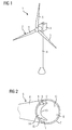
- Fig. 1 shows a wind turbine 1 according to an embodiment.
- the wind turbine 1 comprises a rotor 2 connected to a generator (not shown) arranged inside a nacelle 3.
- the nacelle 3 is arranged at the upper end of a tower 4 of the wind turbine 1.
- the rotor 2 comprises three blades 5. Rotors 2 of this kind may have diameters ranging from, for example, 30 to 160 meters.
- the blades 5 are subjected to high wind loads. At the same time, the blades 5 need to be lightweight. For these reasons, blades 5 in modern wind turbines 1 are manufactured from fiber-reinforced composite materials. Therein, glass fibers are generally preferred over carbon fibers for cost reasons.
- the blades 5 each comprise one or more core members made of a light material to reduce the weight of the blades 5. The core members also lend support to a fiber layup during manufacturing of the blades 5 as well as during operation of the wind turbine 1.
- Fig. 2 shows a perspective view of a root end 6 of one of the blades 5 from Fig. 1 .
- the blade 5 comprises a shell or airfoil 7 enclosing a space 8.
- a web 9 inside the space 8 extends in the longitudinal direction of the blade 5.
- the web 9 is connected along opposite edges 10, 11 to the inside surface 12 of the airfoil 7.
- the web 9 has a recess 13 formed in its end facing towards blade root.
- the recess 13 has a parabolic shape defined by a base section 14 and tip sections 15, 16 tapering down from the base section 14 towards inner surface 12.
- the airfoil 7 is preferably made from a fiber-reinforced plastic material and, as the case may be, various coatings, the web 9 comprises a fiber-reinforced plastic material and a core member arranged within the fiber-reinforced plastic material.
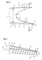
- Fig. 3 illustrates a core member 17 which may be used in a VARTM-process to produce the web 9.
- the core member 17 comprises a number of releasably interlocked elements, for example a base section 18, tip sections 19, 20 and a further base section 21.
- the sections 18, 19, 20 and 21 are made from plywood plates, i.e. plates comprising a number of wooden layers glued together, by cutting or other material removal operations. Having separate elements or sections 18, 19, 20 and 21 allows the raw plates to be of a standard size simplifying storage and manufacturing. Also, having separate elements or sections 18, 19, 20 and 21 may simplify assembly of the core member 17 in- or outside a mold used in the VARTM-process.
- the section 18, 19 and 20 are shaped so as to define a parabolic recess 22, the tip sections 19, 20 tapering down from the base section 18.
- the tip sections 18, 19 may form a tongue-and-groove joint 23 with the base section 18, respectively.
- the tongue and groove may respectively have curved shape as indicated in Fig. 3 .
- the base section 18 may be connected to the further base section 21 by locking elements 24.
- the locking elements 24 may have a U-shape, each locking element 24 being engaged with both sections 18, 21.
- the entire core member 17 (or some of its elements or sections) is made of plastic foam, e.g. PET or PU.
- Fig. 3 illustrates in dashed lines support elements 25, 26 and 27, which are associated with the sections 20, 18 and 21 respectively and extend along respective upper and lower edges 28, 29 of the core member 17.
- the support elements associated with the upper edge 28 is not shown in Fig. 3 for reasons of clarity.
- Each support element 25, 26 and 27 has a substantially triangular cross-section 30 comprising an upper groove 31, in which a respective edge (corresponding to the edge 29) of the sections 20, 18 and 21 is engaged. Curved sides 32, 33 of the support elements 25, 26 and 27 lend support to a fiber layup as will be explained hereinafter.
- Fig. 4 illustrates the tip section 20 and the support element 25 from Fig. 3 as well as a layup 34 of fiber material.
- the layup 34 may comprise a plurality of fiber mats 35, the fiber mats 35 overlapping one another at least partially.
- Each fiber mat 35 may comprise rovings in criss-cross arrangement.
- the fiber mats 35 extend beyond the tip section 20 in a sideways direction Y and a longways direction X in order to reduce the risk of delamination from the inner surface 12 of the airfoil 7, cf. Fig. 2 .
- the fiber mats 35 are attached to the tip section 20 by staples 36 using a staple gun (not shown). Yet, other ways of fastening the fiber mats 35 to the tip section 20 are also possible.
- the staples 36 are driven so deeply into the wood of the tips section 20 that they do not damage a vacuum bag employed in the VARTM-process described hereinafter.
- the tip section 20 including the (dry) layup 34 and, as the case may be, the support element 25 may be prepacked and delivered to a mold 40 shown in Fig. 5 .
- the entire core 17 may, as a whole or each section 18, 19, 20, 21 separately, be prepacked with a (dry) layup 34 and delivered to the mold 40.
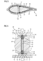
- Fig. 5 shows the mold 40 in a cross-section
- Fig. 6 illustrates an enlarged region VI from Fig. 5
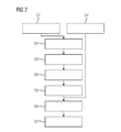
- Fig. 7 illustrating a flow diagram of the VARTM-process now described.
- the mold 40 may be a closed mold comprising a lower and an upper half 37, 38.
- the upper half 38 is positioned next to the lower half 37 and turned by 180 degrees compared to Fig. 5 .
- a layup 39 of fiber material comprising for example fiber mats as shown in Fig. 4 , is created on the lower and upper half 37, 38 respectively.
- vacuum is applied underneath a respective layup 39.
- a suction pump 41 ( Fig. 6 ) may create a vacuum between an outermost layer 42 of the layup 39 and an inside mold surface 43.
- the outermost layer 42 may have a lower air permeability then layers 44 underneath layer 42.
- This step of creating a layup 39 in the mold 40 is illustrated by step S2 in Fig. 7 .
- the layup 39 comprises dry fibers. According to another embodiment, pre-impregnated fibers may be used.
- the core member 17 is, as a whole or each section 18, 19, 20, 21 separately, arranged inside the lower half 37 of the mold 40 on top of the layup 39. If the sections 18, 19, 20, 21 are brought into the mold 40 separately, they are connected to one another by means of the tongue-and-groove joints 23 and/or the locking elements 24 inside the mold 40, otherwise they are connected outside the mold 40.
- the core member 17, as a whole or each section 18, 19, 20, 21 separately, may at the point of arranging them on the layup 39 be covered by the layup 34.
- the "bare" core member 17 is arranged inside the mold 40 and then the layup 34 is arranged on the core member 17. Portions of the layup 34 covering the base section 18 as well as parts of the recess 22 is shown in dashed lines in Fig. 6 .
- Providing the layup 39 on the core member 17 before arranging the core member 17 inside the mold 40 is indicated by step S1.
- Step S4 indicates an embodiment where the layup 39 is provided on the core member 17 after arranging the same inside the mold 40.
- the sections 18, 20 and 21 are covered with the layup 39 inside the mold 40, and the tip section 22 is prepacked as described in connection with Fig. 4 .
- the step of prepacking is indicated by step S1' in Fig. 7 .
- the support elements 25, 26 and 27 should be positioned on the layup 39.
- the edge 29 of the core member 17 is then brought into engagement with the groove 31 in each of the support elements 25, 26 and 27.
- core members 45 are wrapped into a vacuum bag 46, respectively. Then, the core members 45 are arranged in the hollow spaces left and right of the core member 17 as shown in Fig. 6 . This corresponds to step S5 in Fig. 7 .
- this tip section 19 is now connected to the base section 18 by means of the tongue-and-groove joint 23 in step S6.
- the support elements 25' (other support elements not shown) are now placed at the top, and the groove 31' is brought into engagement with the edge 28 of the core member 17.
- the mold 40 is closed by turning the upper half 38 by 180 degrees and placing it on top of the lower half 37. In this manner, the layup 39 comes to lie against the support elements 25' as well as the layup 34.
- step S7 ( Fig. 7 ) the resin is injected into the space 47 and the mold 40 is heated in order to cure the resin. If prepreg material is used, the step of injecting the resin is not required.
- the mold 40 is opened and the mold cores 45 are removed.
- the cured rotor blade 5 may then be taken out of the lower half 37 of the mold 40.
- the resin reinforced by the layup 39 corresponds to the airfoil 7
- the resin reinforced by the layup 34 and including the core member 17 corresponds to the web 9.
- the web 9 produced in this manner has the parabolic recess 13 shown in Fig. 2 , and no removal of material is required.
Landscapes
- Engineering & Computer Science (AREA)
- Mechanical Engineering (AREA)
- Chemical & Material Sciences (AREA)
- Composite Materials (AREA)
- Moulding By Coating Moulds (AREA)
- Wind Motors (AREA)
Priority Applications (5)
| Application Number | Priority Date | Filing Date | Title |
|---|---|---|---|
| ES14158529T ES2872401T3 (es) | 2014-03-10 | 2014-03-10 | Un método para fabricar una pala de rotor para una turbina eólica |
| EP14158529.9A EP2918399B1 (de) | 2014-03-10 | 2014-03-10 | Verfahren zur Herstellung eines Windturbinenrotorblatts |
| DK14158529.9T DK2918399T3 (da) | 2014-03-10 | 2014-03-10 | Fremgangsmåde til fremstilling af en rotorvinge for en vindmølle |
| US14/587,297 US9889619B2 (en) | 2014-03-10 | 2014-12-31 | Method for manufacturing a rotor blade for a wind turbine |
| CN201510103584.XA CN104908335B (zh) | 2014-03-10 | 2015-03-10 | 用于制造风力涡轮的转子叶片的方法 |
Applications Claiming Priority (1)
| Application Number | Priority Date | Filing Date | Title |
|---|---|---|---|
| EP14158529.9A EP2918399B1 (de) | 2014-03-10 | 2014-03-10 | Verfahren zur Herstellung eines Windturbinenrotorblatts |
Publications (2)
| Publication Number | Publication Date |
|---|---|
| EP2918399A1 true EP2918399A1 (de) | 2015-09-16 |
| EP2918399B1 EP2918399B1 (de) | 2021-04-28 |
Family
ID=50239455
Family Applications (1)
| Application Number | Title | Priority Date | Filing Date |
|---|---|---|---|
| EP14158529.9A Active EP2918399B1 (de) | 2014-03-10 | 2014-03-10 | Verfahren zur Herstellung eines Windturbinenrotorblatts |
Country Status (5)
| Country | Link |
|---|---|
| US (1) | US9889619B2 (de) |
| EP (1) | EP2918399B1 (de) |
| CN (1) | CN104908335B (de) |
| DK (1) | DK2918399T3 (de) |
| ES (1) | ES2872401T3 (de) |
Cited By (2)
| Publication number | Priority date | Publication date | Assignee | Title |
|---|---|---|---|---|
| DE102016105010A1 (de) * | 2016-03-17 | 2017-09-21 | Hochschule Für Technik Und Wirtschaft Des Saarlandes | Bauteil zur Nutzung von strömendem Fluid und Verfahren zur Herstellung des Bauteils |
| WO2017171703A1 (en) * | 2016-03-28 | 2017-10-05 | General Electric Company | Rotor blade tip mold assembly including solid core and method for forming rotor blade tip |
Families Citing this family (13)
| Publication number | Priority date | Publication date | Assignee | Title |
|---|---|---|---|---|
| GB2529186A (en) * | 2014-08-12 | 2016-02-17 | Vestas Wind Sys As | Improvements relating to wind turbine blade manufacture |
| US9981433B2 (en) * | 2015-09-23 | 2018-05-29 | General Electric Company | Methods for modifying wind turbine blade molds |
| CN106863840B (zh) * | 2017-04-18 | 2019-07-23 | 浙江理工大学 | 基于可充放气/液芯轴套的编织纤维增强结构件制造方法 |
| US10544776B2 (en) | 2017-07-27 | 2020-01-28 | General Electric Company | Injection method and device for connecting and repairing a shear web |
| US11400624B2 (en) * | 2018-09-24 | 2022-08-02 | Raytheon Technologies Corporation | Constant cross section mandrel for CMC components |
| CN113302395B (zh) * | 2018-10-22 | 2024-05-31 | 泰普爱复合材料股份有限公司 | 带有加热的无龙门风力涡轮机腹板安装 |
| WO2020119870A1 (en) * | 2018-12-10 | 2020-06-18 | Vestas Wind Systems A/S | Improvements relating to wind turbine blade manufacture |
| WO2020127926A2 (en) * | 2018-12-20 | 2020-06-25 | Mhi Vestas Offshore Wind A/S | Improvements relating to wind turbine blade manufacture |
| EP3930990B1 (de) * | 2019-02-28 | 2023-04-19 | LM Wind Power A/S | Flexible vorformform zur herstellung einer vorform für eine windturbinenschaufel |
| EP3838576A1 (de) * | 2019-12-19 | 2021-06-23 | Siemens Gamesa Renewable Energy A/S | Verfahren zur handhabung einer windturbinenschaufel |
| EP4319971B1 (de) * | 2021-04-07 | 2025-10-01 | LM Wind Power A/S | Verfahren zur herstellung einer schale einer windturbinenschaufel |
| CN115807731A (zh) * | 2022-11-28 | 2023-03-17 | 明阳智慧能源集团股份公司 | 一种风电叶片腹板及其成型方法 |
| CN119195970A (zh) * | 2024-08-13 | 2024-12-27 | 远景能源有限公司 | 一种风电用模块化热塑腹板结构、其制作方法以及风力发电叶片 |
Citations (5)
| Publication number | Priority date | Publication date | Assignee | Title |
|---|---|---|---|---|
| EP2123431A1 (de) | 2008-05-21 | 2009-11-25 | Siemens Aktiengesellschaft | Verfahren zur Herstellung eines Verbundstoffes und einer Windturbinenschaufel |
| EP2261501A2 (de) * | 2009-05-29 | 2010-12-15 | Nordex Energy GmbH | Verfahren und Vorrichtung zur Montage eines Rotorblatts für eine Windenergieanlage |
| US20110100542A1 (en) * | 2008-06-27 | 2011-05-05 | Repower Systems Ag | Method and manufacturing mold for the production of a rotor blade for a wind turbine |
| EP2441951A1 (de) * | 2010-10-13 | 2012-04-18 | Siemens Aktiengesellschaft | Verfahren zur Herstellung eines Windturbinenrotorblatts |
| US20130075025A1 (en) * | 2011-03-25 | 2013-03-28 | Maurice Guitton | Method of Manufacturing Hollow Composite Parts with In Situ Formed Internal Structures |
Family Cites Families (46)
| Publication number | Priority date | Publication date | Assignee | Title |
|---|---|---|---|---|
| US3239011A (en) * | 1964-11-23 | 1966-03-08 | Parsons Corp | Helicopter rotor blade spar structure |
| US5346367A (en) * | 1984-12-21 | 1994-09-13 | United Technologies Corporation | Advanced composite rotor blade |
| US5547629A (en) * | 1994-09-27 | 1996-08-20 | Competition Composites, Inc. | Method for manufacturing a one-piece molded composite airfoil |
| US6945727B2 (en) * | 2002-07-19 | 2005-09-20 | The Boeing Company | Apparatuses and methods for joining structural members, such as composite structural members |
| US7258828B2 (en) * | 2004-09-03 | 2007-08-21 | Lockheed Martin Corporation | Infusion joining of composite structures |
| JP4699255B2 (ja) * | 2006-03-24 | 2011-06-08 | 三菱重工業株式会社 | 風車翼 |
| US20070251090A1 (en) * | 2006-04-28 | 2007-11-01 | General Electric Company | Methods and apparatus for fabricating blades |
| US7810757B2 (en) * | 2006-11-02 | 2010-10-12 | The Boeing Company | Mounting device for an aircraft |
| GB0717690D0 (en) * | 2007-09-11 | 2007-10-17 | Blade Dynamics Ltd | Wind turbine blade |
| US8171633B2 (en) * | 2007-12-19 | 2012-05-08 | General Electric Company | Method for assembling a multi-segment wind turbine blade |
| US7740453B2 (en) * | 2007-12-19 | 2010-06-22 | General Electric Company | Multi-segment wind turbine blade and method for assembling the same |
| US8167569B2 (en) * | 2007-12-21 | 2012-05-01 | General Electric Company | Structure and method for self-aligning rotor blade joints |
| WO2009155921A1 (en) * | 2008-06-23 | 2009-12-30 | Danmarks Tekniske Universitet | A wind turbine blade with angled girders |
| GB2462308A (en) * | 2008-08-01 | 2010-02-03 | Vestas Wind Sys As | Extension portion for wind turbine blade |
| EP2334932B2 (de) * | 2008-08-25 | 2024-05-01 | Vestas Wind Systems A/S | Anordnung und verfahren zur herstellung einer anordnung |
| US20110158788A1 (en) * | 2008-08-31 | 2011-06-30 | Vestas Wind Systems A/S | A sectional blade |
| CN102308083B (zh) * | 2008-12-05 | 2016-04-13 | 模组风能公司 | 高效风轮机叶片 |
| US7841835B2 (en) * | 2009-02-20 | 2010-11-30 | General Electric Company | Spar cap for wind turbine blades |
| EP2255957B1 (de) * | 2009-05-25 | 2013-07-10 | LM WP Patent Holding A/S | Verfahren zur Herstellung einer Verbundstruktur mit einem vorgefertigten Verstärkungselement |
| GB2470589A (en) * | 2009-05-29 | 2010-12-01 | Vestas Wind Sys As | Branching spar wind turbine blade |
| DE102009031947A1 (de) * | 2009-07-07 | 2011-01-13 | Nordex Energy Gmbh | Rotorblatt für eine Windenergieanlage und Verfahren zu dessen Herstellung |
| JP2011032987A (ja) * | 2009-08-05 | 2011-02-17 | Nitto Denko Corp | 風力発電機ブレード用補強シート、風力発電機ブレードの補強構造、風力発電機および風力発電機ブレードの補強方法 |
| MX341495B (es) * | 2010-01-14 | 2016-08-23 | Neptco Inc * | Componentes de pala de rotor de turbina eolica y metodos para la fabricacion de los mismos. |
| DK2368699T3 (en) * | 2010-03-22 | 2019-01-14 | Vestas Wind Sys As | Process for manufacturing a wing bar for a wind turbine |
| US9500179B2 (en) * | 2010-05-24 | 2016-11-22 | Vestas Wind Systems A/S | Segmented wind turbine blades with truss connection regions, and associated systems and methods |
| US8172539B2 (en) * | 2010-06-17 | 2012-05-08 | General Electric Company | Wind turbine rotor blade joint |
| FR2962175B1 (fr) * | 2010-07-02 | 2012-08-10 | Snecma | Aube a longeron composite integre |
| US20120093627A1 (en) * | 2010-10-18 | 2012-04-19 | Clipper Windpower, Inc. | Method for site specific energy capture optimization through modular rotor blade tip extension |
| US8057189B2 (en) * | 2010-12-15 | 2011-11-15 | General Electric Company | Wind turbine blade with modular leading edge |
| ES2399259B1 (es) * | 2011-05-24 | 2014-02-28 | Gamesa Innovation & Technology, S.L. | Un método de unión para una pala de aerogenerador multi-panel. |
| US8262362B2 (en) * | 2011-06-08 | 2012-09-11 | General Electric Company | Wind turbine blade shear web with spring flanges |
| US8393871B2 (en) * | 2011-07-19 | 2013-03-12 | General Electric Company | Wind turbine blade shear web connection assembly |
| US8257048B2 (en) * | 2011-07-19 | 2012-09-04 | General Electric Company | Wind turbine blade multi-component shear web with intermediate connection assembly |
| US8235671B2 (en) * | 2011-07-19 | 2012-08-07 | General Electric Company | Wind turbine blade shear web connection assembly |
| EP2570254A1 (de) * | 2011-09-15 | 2013-03-20 | Siemens Aktiengesellschaft | Verfahren zur Herstellung eines Windturbinenrotorblatts und Schernetz |
| US9017510B2 (en) * | 2011-12-13 | 2015-04-28 | The Boeing Company | Method and apparatus for fabricating large scale integrated airfoils |
| GB2497578B (en) * | 2011-12-16 | 2015-01-14 | Vestas Wind Sys As | Wind turbine blades |
| US20130216388A1 (en) * | 2012-02-20 | 2013-08-22 | General Electric Company | Box-shaped shear web for wind turbine blades and method of making |
| US9352823B2 (en) * | 2012-04-04 | 2016-05-31 | Hamilton Sundstrand Corporation | Propeller blade with reinforced spar core |
| US20130315747A1 (en) * | 2012-05-23 | 2013-11-28 | Karsten Schibsbye | Wind turbine blade with improved geometry for reinforcing fibers |
| EP2675030B1 (de) * | 2012-06-13 | 2017-03-01 | Nordex Energy GmbH | Strukturbauteil für ein Windenergieanlagenrotorblatt mit einem Blitzschutzleiter |
| US20140010662A1 (en) * | 2012-07-03 | 2014-01-09 | United Technologies Corporation | Composite airfoil with integral platform |
| CN104995400B (zh) * | 2012-12-20 | 2018-03-20 | 维斯塔斯风力系统有限公司 | 风轮机叶片抗剪腹板的对准 |
| US9057276B2 (en) * | 2013-02-06 | 2015-06-16 | Siemens Aktiengesellschaft | Twisted gas turbine engine airfoil having a twisted rib |
| US20140271217A1 (en) * | 2013-03-15 | 2014-09-18 | Modular Wind Energy, Inc. | Efficient wind turbine blade design and associated manufacturing methods using rectangular spars and segmented shear web |
| US9506452B2 (en) * | 2013-08-28 | 2016-11-29 | General Electric Company | Method for installing a shear web insert within a segmented rotor blade assembly |
-
2014
- 2014-03-10 ES ES14158529T patent/ES2872401T3/es active Active
- 2014-03-10 EP EP14158529.9A patent/EP2918399B1/de active Active
- 2014-03-10 DK DK14158529.9T patent/DK2918399T3/da active
- 2014-12-31 US US14/587,297 patent/US9889619B2/en active Active
-
2015
- 2015-03-10 CN CN201510103584.XA patent/CN104908335B/zh active Active
Patent Citations (5)
| Publication number | Priority date | Publication date | Assignee | Title |
|---|---|---|---|---|
| EP2123431A1 (de) | 2008-05-21 | 2009-11-25 | Siemens Aktiengesellschaft | Verfahren zur Herstellung eines Verbundstoffes und einer Windturbinenschaufel |
| US20110100542A1 (en) * | 2008-06-27 | 2011-05-05 | Repower Systems Ag | Method and manufacturing mold for the production of a rotor blade for a wind turbine |
| EP2261501A2 (de) * | 2009-05-29 | 2010-12-15 | Nordex Energy GmbH | Verfahren und Vorrichtung zur Montage eines Rotorblatts für eine Windenergieanlage |
| EP2441951A1 (de) * | 2010-10-13 | 2012-04-18 | Siemens Aktiengesellschaft | Verfahren zur Herstellung eines Windturbinenrotorblatts |
| US20130075025A1 (en) * | 2011-03-25 | 2013-03-28 | Maurice Guitton | Method of Manufacturing Hollow Composite Parts with In Situ Formed Internal Structures |
Cited By (2)
| Publication number | Priority date | Publication date | Assignee | Title |
|---|---|---|---|---|
| DE102016105010A1 (de) * | 2016-03-17 | 2017-09-21 | Hochschule Für Technik Und Wirtschaft Des Saarlandes | Bauteil zur Nutzung von strömendem Fluid und Verfahren zur Herstellung des Bauteils |
| WO2017171703A1 (en) * | 2016-03-28 | 2017-10-05 | General Electric Company | Rotor blade tip mold assembly including solid core and method for forming rotor blade tip |
Also Published As
| Publication number | Publication date |
|---|---|
| ES2872401T3 (es) | 2021-11-02 |
| CN104908335A (zh) | 2015-09-16 |
| DK2918399T3 (da) | 2021-07-05 |
| US9889619B2 (en) | 2018-02-13 |
| EP2918399B1 (de) | 2021-04-28 |
| CN104908335B (zh) | 2019-06-18 |
| US20150251370A1 (en) | 2015-09-10 |
Similar Documents
| Publication | Publication Date | Title |
|---|---|---|
| US9889619B2 (en) | Method for manufacturing a rotor blade for a wind turbine | |
| US10179425B2 (en) | Fibre preform for laying on a curved surface of a mould | |
| US10730251B2 (en) | Mold for manufacturing a component for a wind turbine | |
| US9133817B2 (en) | Method of manufacturing a composite structure with prefabricated reinforcement element | |
| CN106457719B (zh) | 具有改进的纤维过渡的风力涡轮机叶片 | |
| CN102251935B (zh) | 风力涡轮机的叶片 | |
| CN205330872U (zh) | 转子叶片构件和转子叶片 | |
| CN106457696B (zh) | 以两个步骤制造的风力涡轮机叶片部件 | |
| CN105358300B (zh) | 用于制造风力涡轮机叶片的方法和工具以及制造的叶片 | |
| JP2012016948A (ja) | 複合構造物の構成部材を製造する方法 | |
| DK2918398T3 (en) | Fiber reinforced composite material, component and method | |
| CN115666913A (zh) | 用于诸如翼梁帽的增强结构的拉挤纤维增强条带 | |
| EP2927361B1 (de) | Fasermatte, Komponente für eine Windturbine, Vorrichtung zur Herstellung der Fasermatte und Verfahren zur Herstellung der Fasermatte | |
| US12203442B2 (en) | Method and system of manufacturing a wind turbine blade | |
| CN104890254B (zh) | 用于制造风力涡轮的部件的方法 | |
| WO2014053632A1 (en) | Composite spar cap for a rotor blade of a wind turbine and method of manufacturing the composite spar cap | |
| WO2022074215A1 (en) | A method of manufacturing a wind turbine blade part with a flow-enhancing mat, flow enhancing mat and spar cap obtained by said method |
Legal Events
| Date | Code | Title | Description |
|---|---|---|---|
| PUAI | Public reference made under article 153(3) epc to a published international application that has entered the european phase |
Free format text: ORIGINAL CODE: 0009012 |
|
| AK | Designated contracting states |
Kind code of ref document: A1 Designated state(s): AL AT BE BG CH CY CZ DE DK EE ES FI FR GB GR HR HU IE IS IT LI LT LU LV MC MK MT NL NO PL PT RO RS SE SI SK SM TR |
|
| AX | Request for extension of the european patent |
Extension state: BA ME |
|
| 17P | Request for examination filed |
Effective date: 20151106 |
|
| RBV | Designated contracting states (corrected) |
Designated state(s): AL AT BE BG CH CY CZ DE DK EE ES FI FR GB GR HR HU IE IS IT LI LT LU LV MC MK MT NL NO PL PT RO RS SE SI SK SM TR |
|
| RAP1 | Party data changed (applicant data changed or rights of an application transferred) |
Owner name: SIEMENS AKTIENGESELLSCHAFT |
|
| STAA | Information on the status of an ep patent application or granted ep patent |
Free format text: STATUS: EXAMINATION IS IN PROGRESS |
|
| RAP1 | Party data changed (applicant data changed or rights of an application transferred) |
Owner name: SIEMENS GAMESA RENEWABLE ENERGY A/S |
|
| 17Q | First examination report despatched |
Effective date: 20190506 |
|
| GRAP | Despatch of communication of intention to grant a patent |
Free format text: ORIGINAL CODE: EPIDOSNIGR1 |
|
| STAA | Information on the status of an ep patent application or granted ep patent |
Free format text: STATUS: GRANT OF PATENT IS INTENDED |
|
| RIC1 | Information provided on ipc code assigned before grant |
Ipc: B29C 33/76 20060101ALI20201111BHEP Ipc: F03D 1/06 20060101ALI20201111BHEP Ipc: B29C 33/00 20060101ALI20201111BHEP Ipc: B29D 99/00 20100101ALI20201111BHEP Ipc: B29C 70/34 20060101AFI20201111BHEP Ipc: B29L 31/08 20060101ALN20201111BHEP Ipc: B29C 70/46 20060101ALI20201111BHEP |
|
| INTG | Intention to grant announced |
Effective date: 20201125 |
|
| GRAS | Grant fee paid |
Free format text: ORIGINAL CODE: EPIDOSNIGR3 |
|
| GRAA | (expected) grant |
Free format text: ORIGINAL CODE: 0009210 |
|
| STAA | Information on the status of an ep patent application or granted ep patent |
Free format text: STATUS: THE PATENT HAS BEEN GRANTED |
|
| AK | Designated contracting states |
Kind code of ref document: B1 Designated state(s): AL AT BE BG CH CY CZ DE DK EE ES FI FR GB GR HR HU IE IS IT LI LT LU LV MC MK MT NL NO PL PT RO RS SE SI SK SM TR |
|
| REG | Reference to a national code |
Ref country code: GB Ref legal event code: FG4D |
|
| REG | Reference to a national code |
Ref country code: CH Ref legal event code: EP |
|
| REG | Reference to a national code |
Ref country code: AT Ref legal event code: REF Ref document number: 1386629 Country of ref document: AT Kind code of ref document: T Effective date: 20210515 |
|
| REG | Reference to a national code |
Ref country code: DE Ref legal event code: R096 Ref document number: 602014076929 Country of ref document: DE |
|
| REG | Reference to a national code |
Ref country code: IE Ref legal event code: FG4D |
|
| REG | Reference to a national code |
Ref country code: DK Ref legal event code: T3 Effective date: 20210629 |
|
| REG | Reference to a national code |
Ref country code: NL Ref legal event code: FP |
|
| REG | Reference to a national code |
Ref country code: LT Ref legal event code: MG9D |
|
| REG | Reference to a national code |
Ref country code: AT Ref legal event code: MK05 Ref document number: 1386629 Country of ref document: AT Kind code of ref document: T Effective date: 20210428 |
|
| PG25 | Lapsed in a contracting state [announced via postgrant information from national office to epo] |
Ref country code: HR Free format text: LAPSE BECAUSE OF FAILURE TO SUBMIT A TRANSLATION OF THE DESCRIPTION OR TO PAY THE FEE WITHIN THE PRESCRIBED TIME-LIMIT Effective date: 20210428 Ref country code: FI Free format text: LAPSE BECAUSE OF FAILURE TO SUBMIT A TRANSLATION OF THE DESCRIPTION OR TO PAY THE FEE WITHIN THE PRESCRIBED TIME-LIMIT Effective date: 20210428 Ref country code: LT Free format text: LAPSE BECAUSE OF FAILURE TO SUBMIT A TRANSLATION OF THE DESCRIPTION OR TO PAY THE FEE WITHIN THE PRESCRIBED TIME-LIMIT Effective date: 20210428 Ref country code: AT Free format text: LAPSE BECAUSE OF FAILURE TO SUBMIT A TRANSLATION OF THE DESCRIPTION OR TO PAY THE FEE WITHIN THE PRESCRIBED TIME-LIMIT Effective date: 20210428 Ref country code: BG Free format text: LAPSE BECAUSE OF FAILURE TO SUBMIT A TRANSLATION OF THE DESCRIPTION OR TO PAY THE FEE WITHIN THE PRESCRIBED TIME-LIMIT Effective date: 20210728 |
|
| REG | Reference to a national code |
Ref country code: ES Ref legal event code: FG2A Ref document number: 2872401 Country of ref document: ES Kind code of ref document: T3 Effective date: 20211102 |
|
| PG25 | Lapsed in a contracting state [announced via postgrant information from national office to epo] |
Ref country code: NO Free format text: LAPSE BECAUSE OF FAILURE TO SUBMIT A TRANSLATION OF THE DESCRIPTION OR TO PAY THE FEE WITHIN THE PRESCRIBED TIME-LIMIT Effective date: 20210728 Ref country code: PL Free format text: LAPSE BECAUSE OF FAILURE TO SUBMIT A TRANSLATION OF THE DESCRIPTION OR TO PAY THE FEE WITHIN THE PRESCRIBED TIME-LIMIT Effective date: 20210428 Ref country code: PT Free format text: LAPSE BECAUSE OF FAILURE TO SUBMIT A TRANSLATION OF THE DESCRIPTION OR TO PAY THE FEE WITHIN THE PRESCRIBED TIME-LIMIT Effective date: 20210830 Ref country code: SE Free format text: LAPSE BECAUSE OF FAILURE TO SUBMIT A TRANSLATION OF THE DESCRIPTION OR TO PAY THE FEE WITHIN THE PRESCRIBED TIME-LIMIT Effective date: 20210428 Ref country code: RS Free format text: LAPSE BECAUSE OF FAILURE TO SUBMIT A TRANSLATION OF THE DESCRIPTION OR TO PAY THE FEE WITHIN THE PRESCRIBED TIME-LIMIT Effective date: 20210428 Ref country code: LV Free format text: LAPSE BECAUSE OF FAILURE TO SUBMIT A TRANSLATION OF THE DESCRIPTION OR TO PAY THE FEE WITHIN THE PRESCRIBED TIME-LIMIT Effective date: 20210428 Ref country code: IS Free format text: LAPSE BECAUSE OF FAILURE TO SUBMIT A TRANSLATION OF THE DESCRIPTION OR TO PAY THE FEE WITHIN THE PRESCRIBED TIME-LIMIT Effective date: 20210828 Ref country code: GR Free format text: LAPSE BECAUSE OF FAILURE TO SUBMIT A TRANSLATION OF THE DESCRIPTION OR TO PAY THE FEE WITHIN THE PRESCRIBED TIME-LIMIT Effective date: 20210729 |
|
| PG25 | Lapsed in a contracting state [announced via postgrant information from national office to epo] |
Ref country code: CZ Free format text: LAPSE BECAUSE OF FAILURE TO SUBMIT A TRANSLATION OF THE DESCRIPTION OR TO PAY THE FEE WITHIN THE PRESCRIBED TIME-LIMIT Effective date: 20210428 Ref country code: EE Free format text: LAPSE BECAUSE OF FAILURE TO SUBMIT A TRANSLATION OF THE DESCRIPTION OR TO PAY THE FEE WITHIN THE PRESCRIBED TIME-LIMIT Effective date: 20210428 Ref country code: SK Free format text: LAPSE BECAUSE OF FAILURE TO SUBMIT A TRANSLATION OF THE DESCRIPTION OR TO PAY THE FEE WITHIN THE PRESCRIBED TIME-LIMIT Effective date: 20210428 Ref country code: SM Free format text: LAPSE BECAUSE OF FAILURE TO SUBMIT A TRANSLATION OF THE DESCRIPTION OR TO PAY THE FEE WITHIN THE PRESCRIBED TIME-LIMIT Effective date: 20210428 Ref country code: RO Free format text: LAPSE BECAUSE OF FAILURE TO SUBMIT A TRANSLATION OF THE DESCRIPTION OR TO PAY THE FEE WITHIN THE PRESCRIBED TIME-LIMIT Effective date: 20210428 |
|
| REG | Reference to a national code |
Ref country code: DE Ref legal event code: R097 Ref document number: 602014076929 Country of ref document: DE |
|
| PLBE | No opposition filed within time limit |
Free format text: ORIGINAL CODE: 0009261 |
|
| STAA | Information on the status of an ep patent application or granted ep patent |
Free format text: STATUS: NO OPPOSITION FILED WITHIN TIME LIMIT |
|
| 26N | No opposition filed |
Effective date: 20220131 |
|
| PG25 | Lapsed in a contracting state [announced via postgrant information from national office to epo] |
Ref country code: IS Free format text: LAPSE BECAUSE OF FAILURE TO SUBMIT A TRANSLATION OF THE DESCRIPTION OR TO PAY THE FEE WITHIN THE PRESCRIBED TIME-LIMIT Effective date: 20210828 Ref country code: AL Free format text: LAPSE BECAUSE OF FAILURE TO SUBMIT A TRANSLATION OF THE DESCRIPTION OR TO PAY THE FEE WITHIN THE PRESCRIBED TIME-LIMIT Effective date: 20210428 |
|
| PG25 | Lapsed in a contracting state [announced via postgrant information from national office to epo] |
Ref country code: IT Free format text: LAPSE BECAUSE OF FAILURE TO SUBMIT A TRANSLATION OF THE DESCRIPTION OR TO PAY THE FEE WITHIN THE PRESCRIBED TIME-LIMIT Effective date: 20210428 |
|
| PG25 | Lapsed in a contracting state [announced via postgrant information from national office to epo] |
Ref country code: MC Free format text: LAPSE BECAUSE OF FAILURE TO SUBMIT A TRANSLATION OF THE DESCRIPTION OR TO PAY THE FEE WITHIN THE PRESCRIBED TIME-LIMIT Effective date: 20210428 |
|
| REG | Reference to a national code |
Ref country code: CH Ref legal event code: PL |
|
| REG | Reference to a national code |
Ref country code: BE Ref legal event code: MM Effective date: 20220331 |
|
| PG25 | Lapsed in a contracting state [announced via postgrant information from national office to epo] |
Ref country code: LU Free format text: LAPSE BECAUSE OF NON-PAYMENT OF DUE FEES Effective date: 20220310 Ref country code: LI Free format text: LAPSE BECAUSE OF NON-PAYMENT OF DUE FEES Effective date: 20220331 Ref country code: IE Free format text: LAPSE BECAUSE OF NON-PAYMENT OF DUE FEES Effective date: 20220310 Ref country code: CH Free format text: LAPSE BECAUSE OF NON-PAYMENT OF DUE FEES Effective date: 20220331 |
|
| PG25 | Lapsed in a contracting state [announced via postgrant information from national office to epo] |
Ref country code: BE Free format text: LAPSE BECAUSE OF NON-PAYMENT OF DUE FEES Effective date: 20220331 |
|
| PG25 | Lapsed in a contracting state [announced via postgrant information from national office to epo] |
Ref country code: HU Free format text: LAPSE BECAUSE OF FAILURE TO SUBMIT A TRANSLATION OF THE DESCRIPTION OR TO PAY THE FEE WITHIN THE PRESCRIBED TIME-LIMIT; INVALID AB INITIO Effective date: 20140310 |
|
| PG25 | Lapsed in a contracting state [announced via postgrant information from national office to epo] |
Ref country code: MK Free format text: LAPSE BECAUSE OF FAILURE TO SUBMIT A TRANSLATION OF THE DESCRIPTION OR TO PAY THE FEE WITHIN THE PRESCRIBED TIME-LIMIT Effective date: 20210428 Ref country code: CY Free format text: LAPSE BECAUSE OF FAILURE TO SUBMIT A TRANSLATION OF THE DESCRIPTION OR TO PAY THE FEE WITHIN THE PRESCRIBED TIME-LIMIT Effective date: 20210428 |
|
| PG25 | Lapsed in a contracting state [announced via postgrant information from national office to epo] |
Ref country code: TR Free format text: LAPSE BECAUSE OF FAILURE TO SUBMIT A TRANSLATION OF THE DESCRIPTION OR TO PAY THE FEE WITHIN THE PRESCRIBED TIME-LIMIT Effective date: 20210428 |
|
| PG25 | Lapsed in a contracting state [announced via postgrant information from national office to epo] |
Ref country code: MT Free format text: LAPSE BECAUSE OF FAILURE TO SUBMIT A TRANSLATION OF THE DESCRIPTION OR TO PAY THE FEE WITHIN THE PRESCRIBED TIME-LIMIT Effective date: 20210428 |
|
| PGFP | Annual fee paid to national office [announced via postgrant information from national office to epo] |
Ref country code: NL Payment date: 20250325 Year of fee payment: 12 |
|
| PGFP | Annual fee paid to national office [announced via postgrant information from national office to epo] |
Ref country code: ES Payment date: 20250423 Year of fee payment: 12 |
|
| PGFP | Annual fee paid to national office [announced via postgrant information from national office to epo] |
Ref country code: GB Payment date: 20260323 Year of fee payment: 13 |
|
| PGFP | Annual fee paid to national office [announced via postgrant information from national office to epo] |
Ref country code: DK Payment date: 20260323 Year of fee payment: 13 Ref country code: DE Payment date: 20250731 Year of fee payment: 13 |
|
| PGFP | Annual fee paid to national office [announced via postgrant information from national office to epo] |
Ref country code: FR Payment date: 20260323 Year of fee payment: 13 |