EP2918433A2 - Fahrzeugklimaanlagenvorrichtung - Google Patents
Fahrzeugklimaanlagenvorrichtung Download PDFInfo
- Publication number
- EP2918433A2 EP2918433A2 EP15158916.5A EP15158916A EP2918433A2 EP 2918433 A2 EP2918433 A2 EP 2918433A2 EP 15158916 A EP15158916 A EP 15158916A EP 2918433 A2 EP2918433 A2 EP 2918433A2
- Authority
- EP
- European Patent Office
- Prior art keywords
- air conditioning
- projecting portion
- conditioning duct
- projecting
- air
- Prior art date
- Legal status (The legal status is an assumption and is not a legal conclusion. Google has not performed a legal analysis and makes no representation as to the accuracy of the status listed.)
- Granted
Links
Images


Classifications
-
- B—PERFORMING OPERATIONS; TRANSPORTING
- B60—VEHICLES IN GENERAL
- B60H—ARRANGEMENTS OF HEATING, COOLING, VENTILATING OR OTHER AIR-TREATING DEVICES SPECIALLY ADAPTED FOR PASSENGER OR GOODS SPACES OF VEHICLES
- B60H1/00—Heating, cooling or ventilating devices
- B60H1/00507—Details, e.g. mounting arrangements, desaeration devices
- B60H1/00557—Details of ducts or cables
- B60H1/00564—Details of ducts or cables of air ducts
-
- B—PERFORMING OPERATIONS; TRANSPORTING
- B60—VEHICLES IN GENERAL
- B60K—ARRANGEMENT OR MOUNTING OF PROPULSION UNITS OR OF TRANSMISSIONS IN VEHICLES; ARRANGEMENT OR MOUNTING OF PLURAL DIVERSE PRIME-MOVERS IN VEHICLES; AUXILIARY DRIVES FOR VEHICLES; INSTRUMENTATION OR DASHBOARDS FOR VEHICLES; ARRANGEMENTS IN CONNECTION WITH COOLING, AIR INTAKE, GAS EXHAUST OR FUEL SUPPLY OF PROPULSION UNITS IN VEHICLES
- B60K37/00—Dashboards
- B60K37/20—Dashboard panels
-
- B—PERFORMING OPERATIONS; TRANSPORTING
- B60—VEHICLES IN GENERAL
- B60H—ARRANGEMENTS OF HEATING, COOLING, VENTILATING OR OTHER AIR-TREATING DEVICES SPECIALLY ADAPTED FOR PASSENGER OR GOODS SPACES OF VEHICLES
- B60H1/00—Heating, cooling or ventilating devices
- B60H1/24—Ventilating devices where the heating or cooling is irrelevant
- B60H1/241—Ventilating devices where the heating or cooling is irrelevant characterised by the location of ventilation devices in the vehicle
- B60H1/242—Ventilating devices where the heating or cooling is irrelevant characterised by the location of ventilation devices in the vehicle located in the front area
-
- B—PERFORMING OPERATIONS; TRANSPORTING
- B60—VEHICLES IN GENERAL
- B60K—ARRANGEMENT OR MOUNTING OF PROPULSION UNITS OR OF TRANSMISSIONS IN VEHICLES; ARRANGEMENT OR MOUNTING OF PLURAL DIVERSE PRIME-MOVERS IN VEHICLES; AUXILIARY DRIVES FOR VEHICLES; INSTRUMENTATION OR DASHBOARDS FOR VEHICLES; ARRANGEMENTS IN CONNECTION WITH COOLING, AIR INTAKE, GAS EXHAUST OR FUEL SUPPLY OF PROPULSION UNITS IN VEHICLES
- B60K2360/00—Indexing scheme associated with groups B60K35/00 or B60K37/00 relating to details of instruments or dashboards
- B60K2360/60—Structural details of dashboards or instruments
- B60K2360/65—Features of dashboards
- B60K2360/658—Dashboard parts used as air ducts
Definitions
- the present invention relates to a vehicle air conditioning apparatus.
- An instrument panel on which instruments and on-board equipment such as an audio apparatus and an air conditioning apparatus are mounted is disposed in a front portion of a passenger compartment in such a way as to extend in a vehicle's widthwise or transverse direction.
- a front defroster opening which performs as a front defroster is provided on an upper surface portion of the instrument panel which is oriented upwards, and side defroster openings which perform as side defrosters are provided individually at both transverse ends of a rear surface portion of the instrument panel which is oriented to the rear of the passenger compartment.
- a plurality of fins are provided in such a way as to be aligned in the same direction so as to partition the opening for conditioning air to be blown out thereof in a predetermined direction. Then, narrow elongated gaps are defined between the fins, as well as between the outermost fins and edge portions of the air conditioning opening.
- the thin plate-like member such as a plastic card
- the thin plate-like member eventually enters an air conditioning duct, resulting in a drawback in which the thin plate-like member becomes difficult to be taken out of the air conditioning duct.
- the thin plate-like member is prevented from entering the air conditioning duct from the gap by providing the fins in a grid-like fashion so as to divide the gaps in the air conditioning opening into small gap portions.
- the degree of freedom in designing the air conditioning opening is deteriorated, and the provision of such insertion preventive partitions becomes disadvantageous in improving the design properties of the air conditioning opening.
- the air conditioning openings such as side defroster openings which are provided on the rear side (the passenger compartment side) of the instrument panel which is situated relatively near a driver and a front-seat passenger
- the air conditioning openings are easily visualized, and hence, in case such insertion preventive partitions are provided therein in the way described above, the design properties of the air conditioning openings will be affected badly, leaving room for improvement.
- the invention has been made in view of these situations, and an object thereof is to provide a vehicle air conditioning apparatus which is advantageous in improving the design properties of an air conditioning opening while preventing a thin plate-like member from entering an interior of an air conditioning duct.
- a vehicle air conditioning apparatus including:
- the projecting portion may include a first projecting portion and a second projecting portion which are provided at portions in the air conditioning duct which face each other. An end portion of the first projecting portion and an end portion of the second projecting portion are placed at closed position with each other.
- the first projecting portion and the second projecting portion may be provided so as to shift in phase in a direction in which the air conditioning duct extends.
- the end portion of the first projecting portion may be placed further upstream of a flow of conditioning air than the end portion of the second projecting portion in the direction in which the air conditioning duct extends.
- a gap may be formed between the end portion of the first projecting portion and the end portion of the second projecting portion.
- the first projecting portion and the second projecting portion may extend in the direction in which the air conditioning duct extends.
- an area occupied by the first projecting portion within the air conditioning duct may be gradually reduced from a portion of the first projecting portion which is situated downstream of a flow of conditioning air which flows in the air conditioning duct towards a portion of the first projecting portion which is situated upstream of the flow of conditioning air.
- an area occupied by the second projecting portion within the air conditioning duct may be gradually reduced from a portion of the second projecting portion which is situated upstream of a flow of conditioning air which flows in the air conditioning duct towards a portion of the first projecting portion which is situated downstream of the flow of conditioning air.
- the projecting portion may be formed by displacing a part of a wall portion which makes up the air conditioning duct inwards of the air conditioning duct.
- the projecting portion may be formed together with the air conditioning duct through blow molding.
- the thin plate-like member even in the event that the thin plate-like member is erroneously inserted into the air conditioning opening, since the thin plate-like member is brought into abutment with the projecting portion, the thin plate-like member can be prevented from entering the air conditioning duct. Consequently, the necessity is obviated of providing a countermeasure against the erroneous insertion of the thin plate-like member in which the gaps in the air conditioning opening are divided into small gap portions by providing a plurality of partitions in each gap.
- this configuration of the invention is advantageous in realizing an improvement in design properties of the air conditioning opening.
- the projecting amount of each of the projecting portions can be reduced, and therefore, the areas occupied by the projecting portion in the air conditioning duct can be reduced accordingly. Consequently, the area of a passage of conditioning air within the air conditioning duct can be ensured large, and hence, the configuration of the invention is advantageous in ensuring the flow rate of conditioning air.
- the upstream side projecting portion interferes with the downstream side projecting portion within the air conditioning duct, and this obviates the necessity of high accuracy in relation to the projecting height of the upstream side projecting portion and the projecting height of the downstream side projecting portion.
- the invention is advantageous in forming the air conditioning duct with the projecting portions inexpensively and in an ensured fashion.
- the invention is advantageous in ensuring the air conditioning performance of the air conditioning apparatus.
- the invention is advantageous in forming the air conditioning duct with the projecting portions inexpensively and in an ensured fashion.
- an instrument panel 10 includes an upper surface portion (not shown) which is oriented upwards and a rear surface portion 12 which is oriented to the rear of a passenger compartment.
- a front defroster opening (not shown) is provided in a middle portion of the upper surface portion, and this front defroster opening performs as a front defroster which blows conditioning air against a front windshield glass (not shown).
- a side defroster opening 14 is provided at each transverse end of the rear surface portion 12, and this side defroster opening 14 performs as a side defroster which blows conditioning air against a side windshield glass (not shown).
- an air conditioning duct 16 which is disposed inside the instrument panel 10 is connected to the front defroster opening and the side defroster openings 14.
- a vehicle air conditioning apparatus of this embodiment is applied to portions of the air conditioning duct 16 which are connected to the side defroster openings 14.
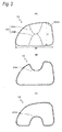
- the side defroster opening 14 exhibits a horizontally elongated shape.
- a bulging portion 1202 for reinforcing the side defroster opening 14 is formed on a front surface of the rear surface portion 12 of the instrument panel 10 at a portion which surrounds an outer circumference of the side defroster opening 14.
- a tubular portion 1204 is provided on a rear surface of the rear surface portion 12 so that the air conditioning duct 16 is fitted thereon.
- a plurality of fins 18 are provided at intervals in the side defroster opening 14 to direct conditioning air towards a front side window glass.
- the plurality of fins 18 which extend in a horizontal direction are disposed in the side defroster opening 14 so as to be aligned vertically.
- the air conditioning duct 16 is made from synthetic resin and is formed through blow molding.
- a parison which is formed into a pipe-like shape from a molten synthetic resin is held by molds, and air is blown into an inside of the parison to obtain a hollow molded product.
- An inlet port 1602 configured to suck in conditioning air supplied from an air conditioner main body, not shown, is provided in a longitudinal middle portion of the air conditioning duct 16.
- air outlet ports 1604 which are connected to the front defroster opening are provided in the longitudinal middle portion of the air conditioning duct 16, and air outlet ports 1606 which are connected individually to the side defroster openings 14 are provided individually at longitudinal ends of the air conditioning duct 16.
- These air outlet ports 1606 are fitted on the tubular portions 1204 of the side defroster openings 14 ( Fig. 4 ), whereby the side defroster openings 14 and the air conditioning duct 16 are connected to each other.
- a portion of the air conditioning duct 16 which lies near the air outlet port 1606 has a cross section whose outline is almost the same as the side defroster opening 14.
- the portion has a horizontally elongated cross section in which a width W is larger than a height H.
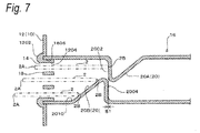
- a projecting portion 20 is provided in an interior of the air conditioning duct 16 in a position lying near the air outlet port 1606, that is, a position lying near the side defroster opening 14, and this projecting portion 20 projects in a direction which intersects a direction in which the fins 18 in the side defroster opening 14 extend.
- the projecting portion 20 projects in the direction of the height H, that is, in a vertical direction so as to be orthogonal to the fins 18.
- a thin plate-like member 2 which is inserted from the side defroster opening 14 is brought into abutment with the projecting portion 20, and therefore, the projecting portion 20 performs to prevent the thin plate-like member 2 from entering the interior of the air conditioning duct 16.
- the thin plate-like member 2 is a plastic card such as a credit card or an electronic money card.
- the projecting portion 20 projects in the direction of the height H, that is, the vertical direction so as to be orthogonal to the fins 18 and is made up of an upper projecting portion (a first projecting portion) 20A which projects downwards from an upper wall of the air conditioning duct 16 and a lower projecting portion (a second projecting portion) 20B which projects upwards from a lower wall of the air conditioning duct 16.
- the upper projecting portion 20A and the lower projecting portion 20B are provided at locations on a middle portion of the air conditioning duct 16 in relation to the direction of the width W which face each other in relation to the direction of the height H (the vertical direction).
- the pair of projecting portions 20 are provided so as to face each other in the vertical direction.
- the projecting portion 20 is made up of the upper projecting portion 20A and the lower projecting portion 20B, and the upper projecting portion 20A and the lower projecting portion 20B are disposed so as to face each other, whereby respective projecting amounts or lengths in the direction of the height H (the vertical direction) of the projecting portions 20 (the upper projecting portion 20A and the lower projecting portion 20B) can be made short.
- a lateral width of the projecting portions 20 can be reduced by suppressing the projecting amounts of the projecting portions 20 (the upper projecting portion 20A and the lower projecting portion 20B). Therefore, compared with a case where the projecting portion 20 is made up of a single projecting portion, an area of an air passage inside the air conditioning duct 16 can be ensured wide.
- the projecting portion 20 is provided at a portion in the air conditioning duct 16 which lies by a predetermined distance inwards from the air outlet port 1606.
- the predetermined distance means a distance which is set so that the thin plate-like member 2 inserted from the side defroster opening 14 is brought into abutment with the projecting portion to thereby be prevented from entering completely in the interior of the air conditioning duct 16.
- the projecting portion 20 is formed as a result of the wall portion which makes up the air conditioning duct 16 being displaced inwards of the air conditioning duct 16.
- this configuration of the invention is advantageous in forming the air conditioning duct 16 with the projecting portion 20 inexpensively and in an ensured fashion by making use of the wall portion which makes up the air conditioning duct 16.
- the projecting portion 20 is formed together with the air conditioning duct 16 through blow molding. Namely, the projecting portion 20 is formed by making use of molds which are used to mold the air conditioning duct 16 in the blow molding.
- the configuration of the invention is advantageous in forming the projecting portion 20 easily and in an ensured fashion.
- the projecting portion 20 includes the upstream side projecting portion 20A and the downstream side projecting portion 20B which are provided at the locations on the middle portion of the air conditioning duct 16 in relation to the direction of the width W which face each other in relation to the direction of the height H.
- the upper projecting portion 20A and the lower projecting portion 20B extend along the direction in which the air conditioning duct 16 extends.
- the upper projecting portion 20A and the lower projecting portion 20B are provided so as to shift in phase in the direction in which the air conditioning duct 16 extends. Namely, the upper projecting portion 20A is disposed further upstream of a flow of air which flows in the air conditioning duct 16 than the lower projecting portion 20B. When looking at the air conditioning duct 16 from the direction of the height H, a downstream end 2002 of the upper projecting portion 20A and an upstream end 2004 of the lower projecting portion 20B overlap.
- the upper projecting portion 20A is formed so that an area occupied by the upper projecting portion 20A within the air conditioning duct 16 is gradually reduced from the downstream side towards the upstream side of the flow of conditioning air which flows in the air conditioning duct 16.
- the upper projecting portion 20A is formed into a downwardly inclined shape so that the projecting amount thereof into the air conditioning duct 16 increases gradually as it extends from the upstream side to the downstream side of the air conditioning duct 16. Consequently, an end portion (a projecting end) of the downstream end 2002 of the upper projecting portion 20A constitutes a portion which projects most into the interior of the air conditioning duct 16.
- the configuration of the upper projecting portion 20A is advantageous in allowing the function of the side defroster to be exhibited effectively.
- the lower projecting portion 20B is formed so that an area occupied by the lower projecting portion 20B within the air conditioning duct 16 is gradually reduced from the upstream side towards the downstream side of the flow of conditioning air which flows in the air conditioning duct 16.
- the lower projecting portion 20B is formed into an upwardly inclined shape so that the projecting amount thereof into the air conditioning duct 16 increases gradually as it extends from the downstream side to the upstream side of the air conditioning duct 16. Consequently, an end portion (a projecting end) of the upstream end 2004 of the lower projecting portion 20B constitutes a portion which projects most into the interior of the air conditioning duct 16.
- the lower projecting portion 20B When the lower projecting portion 20B is configured in the way described above, disturbance to the flow of conditioning air which would otherwise be caused by the lower projecting portion 20B is suppressed, whereby conditioning air is allowed to be blown from the side defroster opening 14 against the front side window glass in a stable fashion.
- the configuration of the lower projecting portion 20B is advantageous in allowing the function of the side defroster to be exhibited effectively.
- the end portion (the projecting end) of the downstream end 2002 which constitutes the portion which projects most in the upper projecting portion 20A and the end portion (the projecting end) of the upstream end 2004 which constitutes the portion which projects most in the lower projecting portion 20B are disposed so as to face each other in the direction of the height H (the vertical direction) and are located close enough to be brought into contact with each other or are brought into abutment with each other.
- the other widthwise end 2B of the thin plate-like member 2 can be brought into abutment with the upper projecting portion 20A and the lower projecting portion 20B.
- the end portion 2B of the thin plate-like member 2 which enters from an upper half portion of the side defroster opening 14 in the direction of the height H can be brought into abutment with the downstream end 2002 of the upstream side projecting portion 20A.
- the end portion 2B of the thin plate-like member 2 which enters from a lower half portion of the side defroster opening 14 in the direction of the height can be brought into abutment with a portion of the downstream side projecting portion 20B which lies upstream of a downstream end 2010 of the downstream side projecting portion 20B.
- the end portion 2B of the thin plate-like member 2 which enters from a middle portion of the side defroster opening 14 in the direction of the height H (the vertical direction) can be brought into abutment with the downstream end 2002 of the upper projecting portion 20Aor a portion of the lower projecting portion 20B which lies upstream of the downstream end 2010 of the lower projecting portion 20B.
- the thin plate-like member 2 can be prevented from entering the air conditioning duct 16.
- the upper projecting portion 20A and the lower projecting portion 20B are provided in the interior of the air conditioning duct 16 in the position which lies by a predetermined distance inwards away from the air outlet port 1606.
- the upper projecting portion 20A and the lower projecting portion20B are provided as far away from the side defroster opening 14 as possible, and therefore, disturbance to a flow of conditioning air blown out from the side defroster opening 14 can be restricted. Consequently, it is possible to prevent the ingress of the thin plate-like member 2 into the air conditioning duct 16 while allowing the side defroster opening 4 to exhibit the function of the side defroster.
- the two projecting portions 20, that is, the upper projecting portion 20A and the lower projecting portion 20B are provided close enough to be brought into contact with each other or are provided so as to be brought into abutment with each other while the two projecting portions 20 are facing each other vertically. Therefore, compared with a case where the projecting portion 20 is provided at one location in the air conditioning duct 16, the area (the lateral width) occupied by the projecting portion 20 within the air conditioning duct 16 is reduced, while making it sure to acquire a large area for the passage of air in the air conditioning duct 16. Thus, this configuration is advantageous in ensuring the flow rate of conditioning air.
- the projecting portion 20 in relation to providing the projecting portion 20 through blow molding, when the projecting portion 20 is provided at one location in the air conditioning duct 16, the projecting portion 20 needs to project in height from the location where the projecting portion 20 is provided to a wall portion which faces the location vertically, thereby increasing the height-wise dimension of the projecting portion 20. Because of this, when taking draft angles of molds into consideration, the width of the projecting portion 20 is increased, which inevitably increases the area occupied by the projecting portion 20 within the air conditioning duct 16.
- the projecting portions 20 when the projecting portions 20 are provided at the locations in the air conditioning duct 16 which face each other, the projecting portions 20 only have to project to the middle portion in the interior of the air conditioning duct 16, thereby reducing the height-wise dimensions of the projecting portions 20. Because of this, even when the draft angles of the molds are taken into consideration, the width of the projecting portions 20 can be reduced, whereby the area occupied by each of the projecting portions 20 in the air conditioning duct 16 can be reduced.
- the air conditioning duct 16 is formed through blow molding and extends over almost the full width of the vehicle.
- the air conditioning duct 16 has the large shape, the parison tends to be deformed easily, thereby facilitating the generation of a thin portion.
- a conventional air conditioning duct 16 tends to have a thin portion, and hence, the rigidity thereof is weakened, whereby the conventional air conditioning duct 16 is easily deformed.
- the assemblage of the air outlet port 1606 to the side defroster opening 14 requires care, and hence, the conventional air conditioning duct 16 is disadvantageous in enhancing the efficiency of the assembling work thereof.
- the embodiment of the invention is advantageous in enhancing the efficiency of the assembling work of the air conditioning duct 16.
- a relative position between an upstream side projecting portion 20A and downstream side projecting portion 20B differs from that of the first embodiment.
- an end portion (a projecting end) of a downstream end 2002 of the upper projecting portion 20A and an end portion (a projecting end) of an upstream end 2004 of the lower projecting portion 20B are provided so as to overlap in a direction in which an air conditioning duct 16 extends.
- a gap S1 defined in the direction in which the air conditioning duct 16 extends is provided between the end portion (the projecting end) of the downstream end 2002 of the upper projecting portion 20A and the end portion (the projecting end) of the upstream end 2004 of the lower projecting portion 20B.
- the configuration of the second embodiment is advantageous in forming the air conditioning duct 16 with the projecting portion 20 inexpensively and in an ensured fashion.
Landscapes
- Engineering & Computer Science (AREA)
- Mechanical Engineering (AREA)
- Chemical & Material Sciences (AREA)
- Combustion & Propulsion (AREA)
- Transportation (AREA)
- Physics & Mathematics (AREA)
- Thermal Sciences (AREA)
- Air-Conditioning For Vehicles (AREA)
- Instrument Panels (AREA)
- Duct Arrangements (AREA)
Applications Claiming Priority (1)
| Application Number | Priority Date | Filing Date | Title |
|---|---|---|---|
| JP2014049789A JP6311371B2 (ja) | 2014-03-13 | 2014-03-13 | 車両の空調装置 |
Publications (3)
| Publication Number | Publication Date |
|---|---|
| EP2918433A2 true EP2918433A2 (de) | 2015-09-16 |
| EP2918433A3 EP2918433A3 (de) | 2015-10-14 |
| EP2918433B1 EP2918433B1 (de) | 2018-05-30 |
Family
ID=52706002
Family Applications (1)
| Application Number | Title | Priority Date | Filing Date |
|---|---|---|---|
| EP15158916.5A Active EP2918433B1 (de) | 2014-03-13 | 2015-03-13 | Fahrzeugklimaanlagenvorrichtung |
Country Status (4)
| Country | Link |
|---|---|
| EP (1) | EP2918433B1 (de) |
| JP (1) | JP6311371B2 (de) |
| CN (1) | CN104908553B (de) |
| BR (1) | BR102015005039B1 (de) |
Cited By (1)
| Publication number | Priority date | Publication date | Assignee | Title |
|---|---|---|---|---|
| DE102021002173A1 (de) | 2021-04-26 | 2022-10-27 | Truma Gerätetechnik GmbH & Co. KG | Klimagerät |
Families Citing this family (1)
| Publication number | Priority date | Publication date | Assignee | Title |
|---|---|---|---|---|
| JP6542719B2 (ja) * | 2016-07-07 | 2019-07-10 | しげる工業株式会社 | 車両用デフロスタ装置 |
Citations (2)
| Publication number | Priority date | Publication date | Assignee | Title |
|---|---|---|---|---|
| JP2006123803A (ja) | 2004-10-29 | 2006-05-18 | Nissan Diesel Motor Co Ltd | 空調用ダクト接続構造及び接続方法 |
| JP2008238853A (ja) | 2007-03-26 | 2008-10-09 | Daikyo Nishikawa Kk | 樹脂製部品の取付構造 |
Family Cites Families (6)
| Publication number | Priority date | Publication date | Assignee | Title |
|---|---|---|---|---|
| DE1868123U (de) * | 1962-12-21 | 1963-02-28 | Kautex Werke Gmbh | Stroemungsduese oder -kanal aus thermoplastischen kunststoff. |
| JP2682441B2 (ja) * | 1994-04-25 | 1997-11-26 | 日本プラスト株式会社 | 樹脂製ダクト |
| JPH10217751A (ja) * | 1997-02-05 | 1998-08-18 | Denso Corp | 空気調和装置 |
| JP2003034115A (ja) * | 2001-07-23 | 2003-02-04 | Mitsubishi Heavy Ind Ltd | 自動車用空調ダクト |
| JP2006266239A (ja) * | 2005-03-25 | 2006-10-05 | Toyoda Gosei Co Ltd | 車両用吸気ダクト |
| JP4895776B2 (ja) * | 2006-11-24 | 2012-03-14 | 株式会社イノアックコーポレーション | ダクト |
-
2014
- 2014-03-13 JP JP2014049789A patent/JP6311371B2/ja active Active
-
2015
- 2015-03-06 BR BR102015005039-9A patent/BR102015005039B1/pt not_active IP Right Cessation
- 2015-03-10 CN CN201510104286.2A patent/CN104908553B/zh active Active
- 2015-03-13 EP EP15158916.5A patent/EP2918433B1/de active Active
Patent Citations (2)
| Publication number | Priority date | Publication date | Assignee | Title |
|---|---|---|---|---|
| JP2006123803A (ja) | 2004-10-29 | 2006-05-18 | Nissan Diesel Motor Co Ltd | 空調用ダクト接続構造及び接続方法 |
| JP2008238853A (ja) | 2007-03-26 | 2008-10-09 | Daikyo Nishikawa Kk | 樹脂製部品の取付構造 |
Cited By (3)
| Publication number | Priority date | Publication date | Assignee | Title |
|---|---|---|---|---|
| DE102021002173A1 (de) | 2021-04-26 | 2022-10-27 | Truma Gerätetechnik GmbH & Co. KG | Klimagerät |
| WO2022228711A1 (de) | 2021-04-26 | 2022-11-03 | Truma Gerätetechnik GmbH & Co. KG | Klimagerät |
| DE102021002173B4 (de) | 2021-04-26 | 2023-03-23 | Truma Gerätetechnik GmbH & Co. KG | Klimagerät |
Also Published As
| Publication number | Publication date |
|---|---|
| JP6311371B2 (ja) | 2018-04-18 |
| BR102015005039B1 (pt) | 2022-08-30 |
| JP2015174467A (ja) | 2015-10-05 |
| BR102015005039A2 (pt) | 2016-05-31 |
| EP2918433A3 (de) | 2015-10-14 |
| EP2918433B1 (de) | 2018-05-30 |
| CN104908553B (zh) | 2017-04-12 |
| CN104908553A (zh) | 2015-09-16 |
Similar Documents
| Publication | Publication Date | Title |
|---|---|---|
| US20170057337A1 (en) | Vehicle front section air intake structure | |
| US20130303071A1 (en) | Air feed structure for vehicle | |
| US20140256244A1 (en) | Air conditioning device for vehicle | |
| EP3498505B1 (de) | Fahrzeug mit einer kanalstruktur einer klimaanlage | |
| JP2015020566A (ja) | 車両用空調装置の吹出口構造 | |
| US20160075310A1 (en) | Front defroster nozzle device | |
| EP2275294A1 (de) | Ablaufwanne | |
| EP2918433B1 (de) | Fahrzeugklimaanlagenvorrichtung | |
| US11511602B2 (en) | Wind direction adjusting apparatus | |
| JP6883452B2 (ja) | 車両用空気吹出装置 | |
| CN108473103B (zh) | 用于安装机动车辆的雷达的安装装置 | |
| JP2017013704A (ja) | 車両用空調装置及びその車両用空調装置を搭載した車両 | |
| US20070128997A1 (en) | Vehicle air duct structure | |
| JP6080656B2 (ja) | 吹出口装置 | |
| US20070184770A1 (en) | Duct apparatus | |
| JP6232330B2 (ja) | インストルメントパネル | |
| JP6109000B2 (ja) | デフロスタ | |
| CN108583196B (zh) | 除霜器构造 | |
| JP2010111207A (ja) | 車両空調装置用の導風装置 | |
| CN106314287B (zh) | 车辆用外后视镜装置 | |
| JP2023003681A (ja) | サイドデフロスタの吹き出し口構造 | |
| JP2008126973A (ja) | 車両用ヘッドアップディスプレイ部構造 | |
| CN110509829B (zh) | 车辆用杯架周边构造 | |
| JP6012435B2 (ja) | 車両用デフロスタ装置のダクト構造 | |
| US20210347228A1 (en) | Front defroster nozzle |
Legal Events
| Date | Code | Title | Description |
|---|---|---|---|
| PUAL | Search report despatched |
Free format text: ORIGINAL CODE: 0009013 |
|
| PUAI | Public reference made under article 153(3) epc to a published international application that has entered the european phase |
Free format text: ORIGINAL CODE: 0009012 |
|
| 17P | Request for examination filed |
Effective date: 20150313 |
|
| AK | Designated contracting states |
Kind code of ref document: A2 Designated state(s): AL AT BE BG CH CY CZ DE DK EE ES FI FR GB GR HR HU IE IS IT LI LT LU LV MC MK MT NL NO PL PT RO RS SE SI SK SM TR |
|
| AX | Request for extension of the european patent |
Extension state: BA ME |
|
| AK | Designated contracting states |
Kind code of ref document: A3 Designated state(s): AL AT BE BG CH CY CZ DE DK EE ES FI FR GB GR HR HU IE IS IT LI LT LU LV MC MK MT NL NO PL PT RO RS SE SI SK SM TR |
|
| AX | Request for extension of the european patent |
Extension state: BA ME |
|
| RIC1 | Information provided on ipc code assigned before grant |
Ipc: B60K 37/02 20060101ALI20150904BHEP Ipc: B60H 1/00 20060101AFI20150904BHEP |
|
| STAA | Information on the status of an ep patent application or granted ep patent |
Free format text: STATUS: EXAMINATION IS IN PROGRESS |
|
| 17Q | First examination report despatched |
Effective date: 20170410 |
|
| GRAP | Despatch of communication of intention to grant a patent |
Free format text: ORIGINAL CODE: EPIDOSNIGR1 |
|
| STAA | Information on the status of an ep patent application or granted ep patent |
Free format text: STATUS: GRANT OF PATENT IS INTENDED |
|
| INTG | Intention to grant announced |
Effective date: 20171222 |
|
| GRAS | Grant fee paid |
Free format text: ORIGINAL CODE: EPIDOSNIGR3 |
|
| GRAA | (expected) grant |
Free format text: ORIGINAL CODE: 0009210 |
|
| STAA | Information on the status of an ep patent application or granted ep patent |
Free format text: STATUS: THE PATENT HAS BEEN GRANTED |
|
| AK | Designated contracting states |
Kind code of ref document: B1 Designated state(s): AL AT BE BG CH CY CZ DE DK EE ES FI FR GB GR HR HU IE IS IT LI LT LU LV MC MK MT NL NO PL PT RO RS SE SI SK SM TR |
|
| RAP1 | Party data changed (applicant data changed or rights of an application transferred) |
Owner name: MITSUBISHI JIDOSHA KOGYO KABUSHIKI KAISHA Owner name: MITSUBISHI JIDOSHA ENGINEERING KABUSHIKI KAISHA |
|
| REG | Reference to a national code |
Ref country code: GB Ref legal event code: FG4D |
|
| REG | Reference to a national code |
Ref country code: CH Ref legal event code: EP |
|
| REG | Reference to a national code |
Ref country code: AT Ref legal event code: REF Ref document number: 1003243 Country of ref document: AT Kind code of ref document: T Effective date: 20180615 |
|
| REG | Reference to a national code |
Ref country code: IE Ref legal event code: FG4D |
|
| REG | Reference to a national code |
Ref country code: DE Ref legal event code: R096 Ref document number: 602015011553 Country of ref document: DE |
|
| REG | Reference to a national code |
Ref country code: NL Ref legal event code: MP Effective date: 20180530 |
|
| REG | Reference to a national code |
Ref country code: LT Ref legal event code: MG4D |
|
| PG25 | Lapsed in a contracting state [announced via postgrant information from national office to epo] |
Ref country code: ES Free format text: LAPSE BECAUSE OF FAILURE TO SUBMIT A TRANSLATION OF THE DESCRIPTION OR TO PAY THE FEE WITHIN THE PRESCRIBED TIME-LIMIT Effective date: 20180530 Ref country code: SE Free format text: LAPSE BECAUSE OF FAILURE TO SUBMIT A TRANSLATION OF THE DESCRIPTION OR TO PAY THE FEE WITHIN THE PRESCRIBED TIME-LIMIT Effective date: 20180530 Ref country code: CY Free format text: LAPSE BECAUSE OF FAILURE TO SUBMIT A TRANSLATION OF THE DESCRIPTION OR TO PAY THE FEE WITHIN THE PRESCRIBED TIME-LIMIT Effective date: 20180530 Ref country code: BG Free format text: LAPSE BECAUSE OF FAILURE TO SUBMIT A TRANSLATION OF THE DESCRIPTION OR TO PAY THE FEE WITHIN THE PRESCRIBED TIME-LIMIT Effective date: 20180830 Ref country code: FI Free format text: LAPSE BECAUSE OF FAILURE TO SUBMIT A TRANSLATION OF THE DESCRIPTION OR TO PAY THE FEE WITHIN THE PRESCRIBED TIME-LIMIT Effective date: 20180530 Ref country code: NO Free format text: LAPSE BECAUSE OF FAILURE TO SUBMIT A TRANSLATION OF THE DESCRIPTION OR TO PAY THE FEE WITHIN THE PRESCRIBED TIME-LIMIT Effective date: 20180830 Ref country code: LT Free format text: LAPSE BECAUSE OF FAILURE TO SUBMIT A TRANSLATION OF THE DESCRIPTION OR TO PAY THE FEE WITHIN THE PRESCRIBED TIME-LIMIT Effective date: 20180530 |
|
| PG25 | Lapsed in a contracting state [announced via postgrant information from national office to epo] |
Ref country code: GR Free format text: LAPSE BECAUSE OF FAILURE TO SUBMIT A TRANSLATION OF THE DESCRIPTION OR TO PAY THE FEE WITHIN THE PRESCRIBED TIME-LIMIT Effective date: 20180831 Ref country code: HR Free format text: LAPSE BECAUSE OF FAILURE TO SUBMIT A TRANSLATION OF THE DESCRIPTION OR TO PAY THE FEE WITHIN THE PRESCRIBED TIME-LIMIT Effective date: 20180530 Ref country code: LV Free format text: LAPSE BECAUSE OF FAILURE TO SUBMIT A TRANSLATION OF THE DESCRIPTION OR TO PAY THE FEE WITHIN THE PRESCRIBED TIME-LIMIT Effective date: 20180530 Ref country code: RS Free format text: LAPSE BECAUSE OF FAILURE TO SUBMIT A TRANSLATION OF THE DESCRIPTION OR TO PAY THE FEE WITHIN THE PRESCRIBED TIME-LIMIT Effective date: 20180530 |
|
| REG | Reference to a national code |
Ref country code: AT Ref legal event code: MK05 Ref document number: 1003243 Country of ref document: AT Kind code of ref document: T Effective date: 20180530 |
|
| PG25 | Lapsed in a contracting state [announced via postgrant information from national office to epo] |
Ref country code: NL Free format text: LAPSE BECAUSE OF FAILURE TO SUBMIT A TRANSLATION OF THE DESCRIPTION OR TO PAY THE FEE WITHIN THE PRESCRIBED TIME-LIMIT Effective date: 20180530 |
|
| PG25 | Lapsed in a contracting state [announced via postgrant information from national office to epo] |
Ref country code: RO Free format text: LAPSE BECAUSE OF FAILURE TO SUBMIT A TRANSLATION OF THE DESCRIPTION OR TO PAY THE FEE WITHIN THE PRESCRIBED TIME-LIMIT Effective date: 20180530 Ref country code: CZ Free format text: LAPSE BECAUSE OF FAILURE TO SUBMIT A TRANSLATION OF THE DESCRIPTION OR TO PAY THE FEE WITHIN THE PRESCRIBED TIME-LIMIT Effective date: 20180530 Ref country code: PL Free format text: LAPSE BECAUSE OF FAILURE TO SUBMIT A TRANSLATION OF THE DESCRIPTION OR TO PAY THE FEE WITHIN THE PRESCRIBED TIME-LIMIT Effective date: 20180530 Ref country code: AT Free format text: LAPSE BECAUSE OF FAILURE TO SUBMIT A TRANSLATION OF THE DESCRIPTION OR TO PAY THE FEE WITHIN THE PRESCRIBED TIME-LIMIT Effective date: 20180530 Ref country code: EE Free format text: LAPSE BECAUSE OF FAILURE TO SUBMIT A TRANSLATION OF THE DESCRIPTION OR TO PAY THE FEE WITHIN THE PRESCRIBED TIME-LIMIT Effective date: 20180530 Ref country code: SK Free format text: LAPSE BECAUSE OF FAILURE TO SUBMIT A TRANSLATION OF THE DESCRIPTION OR TO PAY THE FEE WITHIN THE PRESCRIBED TIME-LIMIT Effective date: 20180530 Ref country code: DK Free format text: LAPSE BECAUSE OF FAILURE TO SUBMIT A TRANSLATION OF THE DESCRIPTION OR TO PAY THE FEE WITHIN THE PRESCRIBED TIME-LIMIT Effective date: 20180530 |
|
| PG25 | Lapsed in a contracting state [announced via postgrant information from national office to epo] |
Ref country code: IT Free format text: LAPSE BECAUSE OF FAILURE TO SUBMIT A TRANSLATION OF THE DESCRIPTION OR TO PAY THE FEE WITHIN THE PRESCRIBED TIME-LIMIT Effective date: 20180530 Ref country code: SM Free format text: LAPSE BECAUSE OF FAILURE TO SUBMIT A TRANSLATION OF THE DESCRIPTION OR TO PAY THE FEE WITHIN THE PRESCRIBED TIME-LIMIT Effective date: 20180530 |
|
| REG | Reference to a national code |
Ref country code: DE Ref legal event code: R097 Ref document number: 602015011553 Country of ref document: DE |
|
| PLBE | No opposition filed within time limit |
Free format text: ORIGINAL CODE: 0009261 |
|
| STAA | Information on the status of an ep patent application or granted ep patent |
Free format text: STATUS: NO OPPOSITION FILED WITHIN TIME LIMIT |
|
| 26N | No opposition filed |
Effective date: 20190301 |
|
| PG25 | Lapsed in a contracting state [announced via postgrant information from national office to epo] |
Ref country code: SI Free format text: LAPSE BECAUSE OF FAILURE TO SUBMIT A TRANSLATION OF THE DESCRIPTION OR TO PAY THE FEE WITHIN THE PRESCRIBED TIME-LIMIT Effective date: 20180530 |
|
| PG25 | Lapsed in a contracting state [announced via postgrant information from national office to epo] |
Ref country code: MC Free format text: LAPSE BECAUSE OF FAILURE TO SUBMIT A TRANSLATION OF THE DESCRIPTION OR TO PAY THE FEE WITHIN THE PRESCRIBED TIME-LIMIT Effective date: 20180530 |
|
| REG | Reference to a national code |
Ref country code: CH Ref legal event code: PL |
|
| GBPC | Gb: european patent ceased through non-payment of renewal fee |
Effective date: 20190313 |
|
| PG25 | Lapsed in a contracting state [announced via postgrant information from national office to epo] |
Ref country code: AL Free format text: LAPSE BECAUSE OF FAILURE TO SUBMIT A TRANSLATION OF THE DESCRIPTION OR TO PAY THE FEE WITHIN THE PRESCRIBED TIME-LIMIT Effective date: 20180530 Ref country code: LU Free format text: LAPSE BECAUSE OF NON-PAYMENT OF DUE FEES Effective date: 20190313 |
|
| REG | Reference to a national code |
Ref country code: BE Ref legal event code: MM Effective date: 20190331 |
|
| PG25 | Lapsed in a contracting state [announced via postgrant information from national office to epo] |
Ref country code: IE Free format text: LAPSE BECAUSE OF NON-PAYMENT OF DUE FEES Effective date: 20190313 Ref country code: LI Free format text: LAPSE BECAUSE OF NON-PAYMENT OF DUE FEES Effective date: 20190331 Ref country code: CH Free format text: LAPSE BECAUSE OF NON-PAYMENT OF DUE FEES Effective date: 20190331 Ref country code: GB Free format text: LAPSE BECAUSE OF NON-PAYMENT OF DUE FEES Effective date: 20190313 |
|
| PG25 | Lapsed in a contracting state [announced via postgrant information from national office to epo] |
Ref country code: BE Free format text: LAPSE BECAUSE OF NON-PAYMENT OF DUE FEES Effective date: 20190331 |
|
| PG25 | Lapsed in a contracting state [announced via postgrant information from national office to epo] |
Ref country code: TR Free format text: LAPSE BECAUSE OF FAILURE TO SUBMIT A TRANSLATION OF THE DESCRIPTION OR TO PAY THE FEE WITHIN THE PRESCRIBED TIME-LIMIT Effective date: 20180530 |
|
| PG25 | Lapsed in a contracting state [announced via postgrant information from national office to epo] |
Ref country code: MT Free format text: LAPSE BECAUSE OF NON-PAYMENT OF DUE FEES Effective date: 20190313 Ref country code: PT Free format text: LAPSE BECAUSE OF FAILURE TO SUBMIT A TRANSLATION OF THE DESCRIPTION OR TO PAY THE FEE WITHIN THE PRESCRIBED TIME-LIMIT Effective date: 20181001 |
|
| PG25 | Lapsed in a contracting state [announced via postgrant information from national office to epo] |
Ref country code: IS Free format text: LAPSE BECAUSE OF FAILURE TO SUBMIT A TRANSLATION OF THE DESCRIPTION OR TO PAY THE FEE WITHIN THE PRESCRIBED TIME-LIMIT Effective date: 20180930 |
|
| PG25 | Lapsed in a contracting state [announced via postgrant information from national office to epo] |
Ref country code: HU Free format text: LAPSE BECAUSE OF FAILURE TO SUBMIT A TRANSLATION OF THE DESCRIPTION OR TO PAY THE FEE WITHIN THE PRESCRIBED TIME-LIMIT; INVALID AB INITIO Effective date: 20150313 |
|
| PG25 | Lapsed in a contracting state [announced via postgrant information from national office to epo] |
Ref country code: MK Free format text: LAPSE BECAUSE OF FAILURE TO SUBMIT A TRANSLATION OF THE DESCRIPTION OR TO PAY THE FEE WITHIN THE PRESCRIBED TIME-LIMIT Effective date: 20180530 |
|
| PGFP | Annual fee paid to national office [announced via postgrant information from national office to epo] |
Ref country code: DE Payment date: 20260128 Year of fee payment: 12 |
|
| PGFP | Annual fee paid to national office [announced via postgrant information from national office to epo] |
Ref country code: FR Payment date: 20260209 Year of fee payment: 12 |