EP2918434A2 - Carter moteur/boîte de vitesses pour un véhicule automobile - Google Patents
Carter moteur/boîte de vitesses pour un véhicule automobile Download PDFInfo
- Publication number
- EP2918434A2 EP2918434A2 EP14003345.7A EP14003345A EP2918434A2 EP 2918434 A2 EP2918434 A2 EP 2918434A2 EP 14003345 A EP14003345 A EP 14003345A EP 2918434 A2 EP2918434 A2 EP 2918434A2
- Authority
- EP
- European Patent Office
- Prior art keywords
- support bracket
- frame structure
- vehicle frame
- cross member
- support
- Prior art date
- Legal status (The legal status is an assumption and is not a legal conclusion. Google has not performed a legal analysis and makes no representation as to the accuracy of the status listed.)
- Granted
Links
Images


Classifications
-
- B—PERFORMING OPERATIONS; TRANSPORTING
- B60—VEHICLES IN GENERAL
- B60K—ARRANGEMENT OR MOUNTING OF PROPULSION UNITS OR OF TRANSMISSIONS IN VEHICLES; ARRANGEMENT OR MOUNTING OF PLURAL DIVERSE PRIME-MOVERS IN VEHICLES; AUXILIARY DRIVES FOR VEHICLES; INSTRUMENTATION OR DASHBOARDS FOR VEHICLES; ARRANGEMENTS IN CONNECTION WITH COOLING, AIR INTAKE, GAS EXHAUST OR FUEL SUPPLY OF PROPULSION UNITS IN VEHICLES
- B60K5/00—Arrangement or mounting of internal-combustion or jet-propulsion units
- B60K5/12—Arrangement of engine supports
-
- B—PERFORMING OPERATIONS; TRANSPORTING
- B62—LAND VEHICLES FOR TRAVELLING OTHERWISE THAN ON RAILS
- B62D—MOTOR VEHICLES; TRAILERS
- B62D21/00—Understructures, i.e. chassis frame on which a vehicle body may be mounted
- B62D21/02—Understructures, i.e. chassis frame on which a vehicle body may be mounted comprising longitudinally or transversely arranged frame members
-
- B—PERFORMING OPERATIONS; TRANSPORTING
- B62—LAND VEHICLES FOR TRAVELLING OTHERWISE THAN ON RAILS
- B62D—MOTOR VEHICLES; TRAILERS
- B62D21/00—Understructures, i.e. chassis frame on which a vehicle body may be mounted
- B62D21/11—Understructures, i.e. chassis frame on which a vehicle body may be mounted with resilient means for suspension, e.g. of wheels or engine; sub-frames for mounting engine or suspensions
-
- B—PERFORMING OPERATIONS; TRANSPORTING
- B60—VEHICLES IN GENERAL
- B60Y—INDEXING SCHEME RELATING TO ASPECTS CROSS-CUTTING VEHICLE TECHNOLOGY
- B60Y2200/00—Type of vehicle
- B60Y2200/10—Road Vehicles
- B60Y2200/14—Trucks; Load vehicles, Busses
Definitions
- the invention relates to a motor / gearbox mounting for a vehicle, preferably commercial vehicle.
- the engine / transmission mounting is used in particular for the vibration-movable mounting of an internal combustion engine and / or a transmission of the vehicle, expediently on a vehicle frame structure.
- connection constructions for connecting the internal combustion engine and the transmission to the commercial vehicle frame usually include a drive unit of internal combustion engine and transmission.
- the drive unit is usually connected via a motor and gearbox mounting with a ladder frame-shaped, longitudinal and transverse beams comprehensive commercial vehicle frame.
- the cross members are connected elsewhere with the side rails and stabilize and influence the torsional rigidity of the entire commercial vehicle frame and also sometimes absorb forces that are introduced by the engine and transmission storage in the commercial vehicle frame.
- connection constructions for connecting the internal combustion engine and the transmission to the commercial vehicle frame On the other hand connecting structures to connect the cross member with the side rails.
- the various connection constructions require relatively much installation space and, because of the spacing, lead to a rather unfavorable load transfer in this respect.
- An object of the invention is to provide an improved and / or alternative possibility for expediently vibration-movable mounting of an engine and / or transmission of a vehicle.
- the invention provides a support bracket for a support assembly for supporting an engine, in particular an internal combustion engine, and / or a transmission of a vehicle, preferably a utility vehicle, such as a truck or a bus.
- the support bracket is preferably used for load-bearing arrangement between a longitudinal member and a cross member of a vehicle frame structure.
- the support bracket comprises a receiving space for receiving a bearing device for a holding device for mounting the motor and / or the transmission and a connecting device for direct or indirect connection to a cross member of the vehicle frame structure, so that the support bracket can advantageously serve as a storage for the cross member.
- the invention provides a support bracket which expediently serves both as a housing for a (motor and / or transmission) bearing device and as a bearing, in particular base or mounting structure, for a cross member of a vehicle frame structure
- the support bracket is thus preferably designed so that it can take over both the function of a motor and / or transmission mounting as well as the function of a cross member storage.
- the support bracket thus makes it possible, in particular, for forces to be picked up expediently where they are introduced into the vehicle frame structure.
- support bracket weight saving, space savings, cost savings, shortening the assembly time, reducing the storage space and / or reducing the number of parts.
- the support bracket comprises a fastening device for direct or indirect mounting to a longitudinal member of the vehicle frame structure.
- the receiving space can be limited by a bottom wall and two side walls.
- the receiving space can also be limited by a rear wall and / or a top wall.
- the bottom wall, the side walls, the back wall and / or the top wall may e.g. be executed plate, web or bar-shaped.
- the connecting device is expediently formed on the two side walls.
- connection means may comprise one or more attachment openings, preferably extending transversely (eg, at right angles or obliquely) to the sidewall planes.
- the fastening device is preferably also formed on the two side walls.
- the fastening device may be designed on flanges which are separated from the support bracket e.g. protrude laterally.
- the attachment device may further comprise one or more attachment openings, which preferably extend in the sidewall planes and thus in particular quasi parallel thereto.
- the support bracket is suitable for receiving and forwarding the loads (forces) made of the holding device and the cross member.
- the support bracket is designed in particular to act as a load-bearing part of the vehicle frame structure.
- the receiving space is expediently designed so that it can receive the storage device accurately.
- the bearing device is preferably designed for the vibration-movable mounting of the holding device and thus in particular of the engine and / or transmission.
- the support bracket is to be arranged quasi as an intermediate piece between a longitudinal member and a cross member.
- the engine is preferably an internal combustion engine.
- the holding device may be e.g. can be designed as a bearing crossmember.
- the bearing cross member is preferably designed so that it can extend quasi-continuous from one support bracket to the other support bracket.
- the retainer may also include brackets formed on a motor and / or transmission housing, e.g. are infused, are.
- the holding device may comprise separate holders, which expediently extend inwardly from the storage devices. In the context of the invention, embodiments are thus encompassed, in which the holding device extends continuously between two opposing carrying consoles, but also embodiments in which the holding device protrudes from the storage device, as it were, in the form of a cantilever.
- the holding device can thus be made in one piece or in several parts.
- the invention further comprises a support arrangement for an engine and / or a transmission of a vehicle, preferably a utility vehicle.
- the support assembly includes two conveniently located support brackets as described herein.
- a holding device for supporting the engine and / or the transmission is mounted on the storage facilities of the two support brackets.
- a cross member is mounted on the connecting brackets on the support brackets.
- the invention further comprises e.g. ladder frame-shaped vehicle frame structure, with two expediently opposite longitudinal members and one or more cross members.
- the vehicle frame structure includes a first support bracket that receives a bearing device and is directly or indirectly mounted on a side rail of the vehicle frame structure, and a second support bracket which receives a bearing device and is directly or indirectly mounted on the other side rail of the vehicle frame structure.
- the vehicle frame structure is particularly characterized by the fact that a holding device for supporting a motor and / or transmission of the vehicle is mounted on the one hand on the bearing means of the first support bracket and on the other hand on the bearing means of the second console, and also that a cross member on the one hand with the first support bracket and on the other hand connected to the second support bracket.
- the cross member extends at least in sections over and / or laterally of the holding device.
- the cross member may extend at least in sections over and / or laterally of the first support bracket and the second support bracket.
- the cross member may at least partially span the holding device in the longitudinal direction and / or transverse direction of the vehicle frame structure. Alternatively or additionally, the cross member may at least partially span the first support bracket and the second support bracket.
- the cross member and the holding device preferably extend parallel to one another.
- the cross member is preferably designed to cover the holding device and / or the support bracket (s) quasi sandwich.
- the holding device and the cross member can be connected to each other not only by the support brackets, but also between the support brackets, which is e.g. contributes to the increase in stiffness.
- the invention includes a vehicle having at least one support bracket, a support assembly, and / or a vehicle frame structure, as described herein.
- the vehicle is preferably a motor vehicle and / or commercial vehicle, e.g. a truck or a bus.
- the support bracket in particular the fastening device, is not limited to being fastened to a side rail of a ladder-frame-shaped vehicle frame structure, but may also serve for attachment to a vehicle body.
- vehicle frame structure and / or longitudinal members is therefore interpreted broadly within the scope of the invention.
- the vehicle frame structure and / or the longitudinal member may be part of a ladder frame-shaped vehicle frame (eg chassis) or part of a self-supporting vehicle body.
- FIG. 1 shows a perspective view of a support assembly 10 for an internal combustion engine M and a transmission G of a vehicle, in particular a truck.
- the internal combustion engine M and the transmission G can be exemplified in the FIGS. 8 and 9 be seen.
- the support assembly 10 comprises two, according to the invention arranged opposite support brackets 1 and 1 '.
- the support brackets 1 and 1 ' are of identical design, so that the following description is usually only with respect to a support bracket 1.
- the support bracket 1 comprises a receiving space 2 for receiving a bearing device 3.
- the bearing device 3 is used for the vibration-movable mounting for a holding device 4 for mounting the internal combustion engine M and the transmission G.
- the in FIG. 1 shown holding device 4 is designed as a continuous bearing beam, which is mounted on the one hand on the support bracket 1 and on the other hand on the support bracket 1 '.
- the support bracket 1 further comprises a fastening device 5 for mounting to a side member L such as in the FIGS. 8 and 9 shown vehicle frame structure.
- the support bracket 1 further comprises a connecting device 6 for connecting to a cross member Q such as in the FIGS. 8 and 9 shown vehicle frame structure.
- FIG. 2 shows a front view of the support assembly 10 of FIG. 1 ,
- the holding device 4 is mounted on the bearing device 3 of the support bracket 1.
- the holding device 4 is mounted on the bearing device 3 'of the support bracket 1'.
- the cross member Q is connected via the connecting device 6 with the support bracket 1.
- the cross member Q is connected via the connecting device 6 'with the support bracket 1'.
- the support bracket 1 is mounted by means of the fastening device 5 to the longitudinal beam L, while the support bracket 1 'is mounted on the longitudinal member L' via the fastening device 5 '.
- the support bracket 1 is designed as an intermediate piece for the arrangement between the side members L and the cross member Q and serves to receive and forward the loads from the holding device 4 and the cross member Q.
- the support bracket 1 acts both as a housing for the storage device 3 as well as storage, in particular base / mounting structure, for the cross member Q.
- FIG. 3 shows a perspective view of a support bracket 1 of Figures 1 and 2 ,
- the support bracket 1 comprises a receiving space 2, which in FIG. 3 is quasi filled by the storage device 3 and an end portion of the holding device 4, which is why it is provided for clarity purposes with no reference numerals.
- the FIGS. 4 to 6 show the support bracket 1 of FIG. 3 in different views.
- the receiving space 2 is bounded by a bottom wall B, two side walls S, a rear wall R and a top wall O.
- the bottom wall B, the side walls S and the rear wall R are made plate-shaped, while the top wall O is designed rather bar or web-shaped, which allows easy access to the storage device 3.
- the connecting device 6 for connection to the cross member Q is formed on the two side walls S.
- the attachment openings of the connecting device 6 extend transversely (at right angles or obliquely) to the planes of the side walls S.
- the fastening device 5 for mounting on the side member L is also formed on the side walls S. However, the attachment openings of the attachment device 5 extend in the planes of the side walls S.
- the attachment openings of the connecting device 6 and the attachment openings of the fastening device 5 thus extend obliquely, preferably at right angles to each other.
- FIG. 7 shows a perspective view of a support bracket 1 according to another embodiment of the invention.
- the support bracket 1 has laterally projecting flanges F and the flanges F have the fastening device 5 for mounting on the longitudinal member L.
- FIG. 8 shows a perspective view of a vehicle frame structure according to an embodiment of the invention.
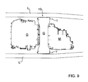
- FIG. 9 shows a top view of the vehicle frame structure of FIG. 8 .
- the vehicle frame structure comprises two mutually opposite longitudinal members L and L 'and a cross member Q.
- the support bracket 1 receives a bearing device 3 and is mounted on the longitudinal member L.
- the support bracket 1 ' receives a bearing device 3' and is mounted on the side member L '.
- the holding device 4 is mounted on the one hand on the bearing device 3 of the support bracket 1 and on the other hand on the bearing means 3 'of the support bracket 1' and holds on the one the internal combustion engine M and on the other the transmission G of the vehicle.
- the cross member Q is on the one hand connected to the support bracket 1 and on the other hand to the support bracket 1 '.
- the cross member Q extends over the holding device 4, the support bracket 1 and the support bracket 1 'and covers the same at least in sections above and laterally sandwiched. In the context of the invention, however, embodiments are also possible in which the cross member Q extends below and / or laterally of the holding device 4 and the support brackets 1 and 1 '.
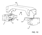
- FIG. 10 shows a perspective view of a support assembly 10 according to another embodiment of the invention.
- the holding device 4 is not designed as a bearing beam, but separate, on the storage facilities 3 and 3 'formed brackets comprises.
- the brackets are similar to a bearing beam for holding a motor M and a gear G, but do not extend consistently from the support bracket 1 to the support bracket 1 ', but are rather cantilever, running in the transverse direction of the vehicle frame structure spaced from each other.
- the brackets z. B. attached to an engine and / or transmission housing (eg molded) to be stored on the storage facilities 3 and 3 'of the support brackets 1 and 1'.
Landscapes
- Engineering & Computer Science (AREA)
- Chemical & Material Sciences (AREA)
- Combustion & Propulsion (AREA)
- Transportation (AREA)
- Mechanical Engineering (AREA)
- Arrangement Of Transmissions (AREA)
- Body Structure For Vehicles (AREA)
- Arrangement Or Mounting Of Propulsion Units For Vehicles (AREA)
- Vehicle Step Arrangements And Article Storage (AREA)
Applications Claiming Priority (1)
| Application Number | Priority Date | Filing Date | Title |
|---|---|---|---|
| DE102013021009.7A DE102013021009A1 (de) | 2013-12-13 | 2013-12-13 | Motor-/Getriebelagerung für ein Kraftfahrzeug |
Publications (3)
| Publication Number | Publication Date |
|---|---|
| EP2918434A2 true EP2918434A2 (fr) | 2015-09-16 |
| EP2918434A3 EP2918434A3 (fr) | 2016-03-16 |
| EP2918434B1 EP2918434B1 (fr) | 2020-07-01 |
Family
ID=51660282
Family Applications (1)
| Application Number | Title | Priority Date | Filing Date |
|---|---|---|---|
| EP14003345.7A Active EP2918434B1 (fr) | 2013-12-13 | 2014-09-27 | Carter moteur/boîte de vitesses pour un véhicule automobile |
Country Status (5)
| Country | Link |
|---|---|
| EP (1) | EP2918434B1 (fr) |
| CN (1) | CN104709060B (fr) |
| BR (1) | BR102014021907B1 (fr) |
| DE (1) | DE102013021009A1 (fr) |
| RU (1) | RU2676369C2 (fr) |
Cited By (1)
| Publication number | Priority date | Publication date | Assignee | Title |
|---|---|---|---|---|
| US11453285B2 (en) | 2018-09-27 | 2022-09-27 | Ford Global Technologies, Llc | Vehicle mount |
Families Citing this family (6)
| Publication number | Priority date | Publication date | Assignee | Title |
|---|---|---|---|---|
| IT201700068690A1 (it) * | 2017-06-20 | 2018-12-20 | Iveco Spa | Sistema per ridurre sollecitazioni d'urto su una cabina veicolare di un veicolo industriale per il trasporto di merci |
| JP7054472B2 (ja) * | 2018-03-02 | 2022-04-14 | いすゞ自動車株式会社 | 車両のクロスメンバ |
| CN109050669B (zh) * | 2018-08-23 | 2021-03-05 | 北京新能源汽车股份有限公司 | 一种前悬置安装支架及汽车 |
| CN111098696B (zh) * | 2018-10-29 | 2023-02-28 | 丰田自动车株式会社 | 动力传递装置 |
| DE102018220728B4 (de) * | 2018-11-30 | 2020-06-10 | Audi Ag | Aggregatelagerung |
| DE102020130889A1 (de) | 2020-11-23 | 2022-05-25 | Man Truck & Bus Se | Querträger, Kraftfahrzeug und Verfahren zum Montieren eines Aggregats |
Family Cites Families (8)
| Publication number | Priority date | Publication date | Assignee | Title |
|---|---|---|---|---|
| RU2185268C2 (ru) * | 2000-06-28 | 2002-07-20 | ООО "Стакол-Инжиниринг" | Способ изготовления тангенциальных расширителей и устройства для его осуществления |
| GB2400590B (en) * | 2000-08-08 | 2005-03-02 | Oshkosh Truck Corp | Vehicle suspension |
| DE10158107C1 (de) * | 2001-11-27 | 2003-02-27 | Daimler Chrysler Ag | Modulartiges Fahrgestell für Nutzfahrzeuge |
| NL2006224C2 (en) * | 2011-02-17 | 2012-08-20 | Daf Trucks Nv | Support structure for a vehicle wheel suspension. |
| RU114637U1 (ru) * | 2011-07-04 | 2012-04-10 | Открытое акционерное общество "ГАЗ" (ОАО "ГАЗ") | Подвеска двигателя автомобиля |
| EP2780210A1 (fr) * | 2011-08-26 | 2014-09-24 | Aktiebolaget SKF | Ensemble bogie de chemin de fer comportant un adaptateur pour suspension |
| CN202827113U (zh) * | 2012-09-19 | 2013-03-27 | 三一重工股份有限公司 | 工程车辆及其散热器固定装置 |
| US9616929B2 (en) * | 2013-06-11 | 2017-04-11 | Volvo Truck Corporation | Cross-member and method for mounting a component to a vehicle frame beam |
-
2013
- 2013-12-13 DE DE102013021009.7A patent/DE102013021009A1/de not_active Withdrawn
-
2014
- 2014-09-04 BR BR102014021907-2A patent/BR102014021907B1/pt active IP Right Grant
- 2014-09-27 EP EP14003345.7A patent/EP2918434B1/fr active Active
- 2014-09-29 RU RU2014139422A patent/RU2676369C2/ru active
- 2014-12-12 CN CN201410759639.8A patent/CN104709060B/zh active Active
Non-Patent Citations (1)
| Title |
|---|
| None |
Cited By (1)
| Publication number | Priority date | Publication date | Assignee | Title |
|---|---|---|---|---|
| US11453285B2 (en) | 2018-09-27 | 2022-09-27 | Ford Global Technologies, Llc | Vehicle mount |
Also Published As
| Publication number | Publication date |
|---|---|
| BR102014021907A2 (pt) | 2016-03-01 |
| RU2014139422A (ru) | 2016-04-20 |
| CN104709060A (zh) | 2015-06-17 |
| CN104709060B (zh) | 2018-12-07 |
| EP2918434A3 (fr) | 2016-03-16 |
| EP2918434B1 (fr) | 2020-07-01 |
| DE102013021009A1 (de) | 2015-06-18 |
| BR102014021907B1 (pt) | 2022-08-02 |
| RU2676369C2 (ru) | 2018-12-28 |
Similar Documents
| Publication | Publication Date | Title |
|---|---|---|
| EP2918434A2 (fr) | Carter moteur/boîte de vitesses pour un véhicule automobile | |
| DE102012203882B4 (de) | Karosserie eines Kraftfahrzeugs | |
| DE102009040896B4 (de) | Anordnung zur Befestigung einer Antriebsbaugruppe im Motorraum eines Fahrzeugs | |
| DE102019107504B4 (de) | Energiespeicher für einen Kraftwagen | |
| DE102007023391B4 (de) | Schutzgehäuse für eine Fahrzeugbatterie und Kraftfahrzeug mit einem derartigen Schutzgehäuse | |
| DE102016203209B4 (de) | Zumindest teilweise elektrisch betreibbares Kraftfahrzeug | |
| EP2542460B1 (fr) | Chassis de roulement pour vehicules utilitaires | |
| DE102016110787A1 (de) | Batteriegehäuse einer Traktionsbatterie eines Kraftfahrzeugs | |
| DE102012203892A1 (de) | Kraftfahrzeug mit einer Karosserie mit einer Bodenstruktur | |
| EP2712788A2 (fr) | Châssis de de véhicule utilitaire doté d'une structure arrière pouvant contenir au moins un composant du véhicule | |
| DE102009009882A1 (de) | Frontenmodul für ein Kraftfahrzeug | |
| EP4200148B1 (fr) | Support de moteur et véhicule avec un tel support de moteur | |
| DE102020123289B3 (de) | Energiespeicher-Bodengruppe für einen elektrisch antreibbaren Personenkraftwagen | |
| DE102011106619A1 (de) | Vorderachssystem für ein Fahrzeug und Kraftfahrzeug | |
| EP3158842A1 (fr) | Véhicule agricole | |
| WO2018100031A1 (fr) | Carrosserie pour véhicule automobile comprenant un ensemble fond qui présente un tunnel central | |
| DE102010025260B4 (de) | Traggestell zur seitlichen Befestigung von Anbauteilen an einem Längsträger einer Nutzfahrzeug-Tragstruktur | |
| DE102006009189B3 (de) | Befestigungsanordnung von Außenanbauteilen an einem Tragrahmen eines Lastkraftwagens | |
| DE102018132167B4 (de) | Fahrzeugbodenstruktur | |
| DE102020004795A1 (de) | Lagersystem für Hochvoltbatterien für Fahrzeuge, insbesondere für Nutzfahrzeuge | |
| DE102008052251A1 (de) | Fahrzeugkarosserie | |
| EP1145891A2 (fr) | Omnibus à gaz ou trolleybus | |
| DE102022127723A1 (de) | Hilfsrahmen mit einem geschraubten Querträger und Kraftfahrzeug | |
| EP2555936A1 (fr) | Carrosserie de véhicule dotée d'un longeron et d'un palier élastomère disposé dessus, servant notamment de support de boîte de vitesses | |
| DE102016115691A1 (de) | Hintere Fahrzeugbodenstruktur |
Legal Events
| Date | Code | Title | Description |
|---|---|---|---|
| PUAI | Public reference made under article 153(3) epc to a published international application that has entered the european phase |
Free format text: ORIGINAL CODE: 0009012 |
|
| AK | Designated contracting states |
Kind code of ref document: A2 Designated state(s): AL AT BE BG CH CY CZ DE DK EE ES FI FR GB GR HR HU IE IS IT LI LT LU LV MC MK MT NL NO PL PT RO RS SE SI SK SM TR |
|
| AX | Request for extension of the european patent |
Extension state: BA ME |
|
| PUAL | Search report despatched |
Free format text: ORIGINAL CODE: 0009013 |
|
| AK | Designated contracting states |
Kind code of ref document: A3 Designated state(s): AL AT BE BG CH CY CZ DE DK EE ES FI FR GB GR HR HU IE IS IT LI LT LU LV MC MK MT NL NO PL PT RO RS SE SI SK SM TR |
|
| AX | Request for extension of the european patent |
Extension state: BA ME |
|
| RIC1 | Information provided on ipc code assigned before grant |
Ipc: B62D 21/11 20060101ALI20160208BHEP Ipc: B60K 5/12 20060101AFI20160208BHEP |
|
| 17P | Request for examination filed |
Effective date: 20160909 |
|
| STAA | Information on the status of an ep patent application or granted ep patent |
Free format text: STATUS: EXAMINATION IS IN PROGRESS |
|
| 17Q | First examination report despatched |
Effective date: 20180307 |
|
| RAP1 | Party data changed (applicant data changed or rights of an application transferred) |
Owner name: MAN TRUCK & BUS SE |
|
| GRAP | Despatch of communication of intention to grant a patent |
Free format text: ORIGINAL CODE: EPIDOSNIGR1 |
|
| STAA | Information on the status of an ep patent application or granted ep patent |
Free format text: STATUS: GRANT OF PATENT IS INTENDED |
|
| INTG | Intention to grant announced |
Effective date: 20200218 |
|
| GRAS | Grant fee paid |
Free format text: ORIGINAL CODE: EPIDOSNIGR3 |
|
| GRAA | (expected) grant |
Free format text: ORIGINAL CODE: 0009210 |
|
| STAA | Information on the status of an ep patent application or granted ep patent |
Free format text: STATUS: THE PATENT HAS BEEN GRANTED |
|
| AK | Designated contracting states |
Kind code of ref document: B1 Designated state(s): AL AT BE BG CH CY CZ DE DK EE ES FI FR GB GR HR HU IE IS IT LI LT LU LV MC MK MT NL NO PL PT RO RS SE SI SK SM TR |
|
| REG | Reference to a national code |
Ref country code: CH Ref legal event code: EP Ref country code: AT Ref legal event code: REF Ref document number: 1285846 Country of ref document: AT Kind code of ref document: T Effective date: 20200715 |
|
| REG | Reference to a national code |
Ref country code: IE Ref legal event code: FG4D Free format text: LANGUAGE OF EP DOCUMENT: GERMAN |
|
| REG | Reference to a national code |
Ref country code: DE Ref legal event code: R096 Ref document number: 502014014380 Country of ref document: DE |
|
| REG | Reference to a national code |
Ref country code: NL Ref legal event code: FP |
|
| REG | Reference to a national code |
Ref country code: SE Ref legal event code: TRGR |
|
| REG | Reference to a national code |
Ref country code: LT Ref legal event code: MG4D |
|
| PG25 | Lapsed in a contracting state [announced via postgrant information from national office to epo] |
Ref country code: BG Free format text: LAPSE BECAUSE OF FAILURE TO SUBMIT A TRANSLATION OF THE DESCRIPTION OR TO PAY THE FEE WITHIN THE PRESCRIBED TIME-LIMIT Effective date: 20201001 |
|
| PG25 | Lapsed in a contracting state [announced via postgrant information from national office to epo] |
Ref country code: FI Free format text: LAPSE BECAUSE OF FAILURE TO SUBMIT A TRANSLATION OF THE DESCRIPTION OR TO PAY THE FEE WITHIN THE PRESCRIBED TIME-LIMIT Effective date: 20200701 Ref country code: LT Free format text: LAPSE BECAUSE OF FAILURE TO SUBMIT A TRANSLATION OF THE DESCRIPTION OR TO PAY THE FEE WITHIN THE PRESCRIBED TIME-LIMIT Effective date: 20200701 Ref country code: CZ Free format text: LAPSE BECAUSE OF FAILURE TO SUBMIT A TRANSLATION OF THE DESCRIPTION OR TO PAY THE FEE WITHIN THE PRESCRIBED TIME-LIMIT Effective date: 20200701 Ref country code: PT Free format text: LAPSE BECAUSE OF FAILURE TO SUBMIT A TRANSLATION OF THE DESCRIPTION OR TO PAY THE FEE WITHIN THE PRESCRIBED TIME-LIMIT Effective date: 20201102 Ref country code: NO Free format text: LAPSE BECAUSE OF FAILURE TO SUBMIT A TRANSLATION OF THE DESCRIPTION OR TO PAY THE FEE WITHIN THE PRESCRIBED TIME-LIMIT Effective date: 20201001 Ref country code: GR Free format text: LAPSE BECAUSE OF FAILURE TO SUBMIT A TRANSLATION OF THE DESCRIPTION OR TO PAY THE FEE WITHIN THE PRESCRIBED TIME-LIMIT Effective date: 20201002 Ref country code: ES Free format text: LAPSE BECAUSE OF FAILURE TO SUBMIT A TRANSLATION OF THE DESCRIPTION OR TO PAY THE FEE WITHIN THE PRESCRIBED TIME-LIMIT Effective date: 20200701 Ref country code: HR Free format text: LAPSE BECAUSE OF FAILURE TO SUBMIT A TRANSLATION OF THE DESCRIPTION OR TO PAY THE FEE WITHIN THE PRESCRIBED TIME-LIMIT Effective date: 20200701 |
|
| PG25 | Lapsed in a contracting state [announced via postgrant information from national office to epo] |
Ref country code: RS Free format text: LAPSE BECAUSE OF FAILURE TO SUBMIT A TRANSLATION OF THE DESCRIPTION OR TO PAY THE FEE WITHIN THE PRESCRIBED TIME-LIMIT Effective date: 20200701 Ref country code: PL Free format text: LAPSE BECAUSE OF FAILURE TO SUBMIT A TRANSLATION OF THE DESCRIPTION OR TO PAY THE FEE WITHIN THE PRESCRIBED TIME-LIMIT Effective date: 20200701 Ref country code: LV Free format text: LAPSE BECAUSE OF FAILURE TO SUBMIT A TRANSLATION OF THE DESCRIPTION OR TO PAY THE FEE WITHIN THE PRESCRIBED TIME-LIMIT Effective date: 20200701 Ref country code: IS Free format text: LAPSE BECAUSE OF FAILURE TO SUBMIT A TRANSLATION OF THE DESCRIPTION OR TO PAY THE FEE WITHIN THE PRESCRIBED TIME-LIMIT Effective date: 20201101 |
|
| REG | Reference to a national code |
Ref country code: DE Ref legal event code: R097 Ref document number: 502014014380 Country of ref document: DE |
|
| PG25 | Lapsed in a contracting state [announced via postgrant information from national office to epo] |
Ref country code: DK Free format text: LAPSE BECAUSE OF FAILURE TO SUBMIT A TRANSLATION OF THE DESCRIPTION OR TO PAY THE FEE WITHIN THE PRESCRIBED TIME-LIMIT Effective date: 20200701 Ref country code: EE Free format text: LAPSE BECAUSE OF FAILURE TO SUBMIT A TRANSLATION OF THE DESCRIPTION OR TO PAY THE FEE WITHIN THE PRESCRIBED TIME-LIMIT Effective date: 20200701 Ref country code: SM Free format text: LAPSE BECAUSE OF FAILURE TO SUBMIT A TRANSLATION OF THE DESCRIPTION OR TO PAY THE FEE WITHIN THE PRESCRIBED TIME-LIMIT Effective date: 20200701 Ref country code: RO Free format text: LAPSE BECAUSE OF FAILURE TO SUBMIT A TRANSLATION OF THE DESCRIPTION OR TO PAY THE FEE WITHIN THE PRESCRIBED TIME-LIMIT Effective date: 20200701 Ref country code: MC Free format text: LAPSE BECAUSE OF FAILURE TO SUBMIT A TRANSLATION OF THE DESCRIPTION OR TO PAY THE FEE WITHIN THE PRESCRIBED TIME-LIMIT Effective date: 20200701 |
|
| REG | Reference to a national code |
Ref country code: CH Ref legal event code: PL |
|
| PLBE | No opposition filed within time limit |
Free format text: ORIGINAL CODE: 0009261 |
|
| STAA | Information on the status of an ep patent application or granted ep patent |
Free format text: STATUS: NO OPPOSITION FILED WITHIN TIME LIMIT |
|
| PG25 | Lapsed in a contracting state [announced via postgrant information from national office to epo] |
Ref country code: AL Free format text: LAPSE BECAUSE OF FAILURE TO SUBMIT A TRANSLATION OF THE DESCRIPTION OR TO PAY THE FEE WITHIN THE PRESCRIBED TIME-LIMIT Effective date: 20200701 |
|
| 26N | No opposition filed |
Effective date: 20210406 |
|
| REG | Reference to a national code |
Ref country code: BE Ref legal event code: MM Effective date: 20200930 |
|
| GBPC | Gb: european patent ceased through non-payment of renewal fee |
Effective date: 20201001 |
|
| PG25 | Lapsed in a contracting state [announced via postgrant information from national office to epo] |
Ref country code: SK Free format text: LAPSE BECAUSE OF FAILURE TO SUBMIT A TRANSLATION OF THE DESCRIPTION OR TO PAY THE FEE WITHIN THE PRESCRIBED TIME-LIMIT Effective date: 20200701 Ref country code: LU Free format text: LAPSE BECAUSE OF NON-PAYMENT OF DUE FEES Effective date: 20200927 |
|
| PG25 | Lapsed in a contracting state [announced via postgrant information from national office to epo] |
Ref country code: BE Free format text: LAPSE BECAUSE OF NON-PAYMENT OF DUE FEES Effective date: 20200930 Ref country code: CH Free format text: LAPSE BECAUSE OF NON-PAYMENT OF DUE FEES Effective date: 20200930 Ref country code: SI Free format text: LAPSE BECAUSE OF FAILURE TO SUBMIT A TRANSLATION OF THE DESCRIPTION OR TO PAY THE FEE WITHIN THE PRESCRIBED TIME-LIMIT Effective date: 20200701 Ref country code: LI Free format text: LAPSE BECAUSE OF NON-PAYMENT OF DUE FEES Effective date: 20200930 Ref country code: GB Free format text: LAPSE BECAUSE OF NON-PAYMENT OF DUE FEES Effective date: 20201001 Ref country code: IE Free format text: LAPSE BECAUSE OF NON-PAYMENT OF DUE FEES Effective date: 20200927 |
|
| REG | Reference to a national code |
Ref country code: AT Ref legal event code: MM01 Ref document number: 1285846 Country of ref document: AT Kind code of ref document: T Effective date: 20200927 |
|
| PG25 | Lapsed in a contracting state [announced via postgrant information from national office to epo] |
Ref country code: AT Free format text: LAPSE BECAUSE OF NON-PAYMENT OF DUE FEES Effective date: 20200927 |
|
| PG25 | Lapsed in a contracting state [announced via postgrant information from national office to epo] |
Ref country code: TR Free format text: LAPSE BECAUSE OF FAILURE TO SUBMIT A TRANSLATION OF THE DESCRIPTION OR TO PAY THE FEE WITHIN THE PRESCRIBED TIME-LIMIT Effective date: 20200701 Ref country code: MT Free format text: LAPSE BECAUSE OF FAILURE TO SUBMIT A TRANSLATION OF THE DESCRIPTION OR TO PAY THE FEE WITHIN THE PRESCRIBED TIME-LIMIT Effective date: 20200701 Ref country code: CY Free format text: LAPSE BECAUSE OF FAILURE TO SUBMIT A TRANSLATION OF THE DESCRIPTION OR TO PAY THE FEE WITHIN THE PRESCRIBED TIME-LIMIT Effective date: 20200701 |
|
| PG25 | Lapsed in a contracting state [announced via postgrant information from national office to epo] |
Ref country code: MK Free format text: LAPSE BECAUSE OF FAILURE TO SUBMIT A TRANSLATION OF THE DESCRIPTION OR TO PAY THE FEE WITHIN THE PRESCRIBED TIME-LIMIT Effective date: 20200701 |
|
| PGFP | Annual fee paid to national office [announced via postgrant information from national office to epo] |
Ref country code: DE Payment date: 20250926 Year of fee payment: 12 |
|
| PGFP | Annual fee paid to national office [announced via postgrant information from national office to epo] |
Ref country code: NL Payment date: 20250925 Year of fee payment: 12 Ref country code: IT Payment date: 20250922 Year of fee payment: 12 |
|
| PGFP | Annual fee paid to national office [announced via postgrant information from national office to epo] |
Ref country code: FR Payment date: 20250925 Year of fee payment: 12 |
|
| PGFP | Annual fee paid to national office [announced via postgrant information from national office to epo] |
Ref country code: SE Payment date: 20250924 Year of fee payment: 12 |