EP2918736A1 - Système permettant d'utiliser les eaux de précipitation pour créer des sources d'eau permanentes et saisonnières - Google Patents
Système permettant d'utiliser les eaux de précipitation pour créer des sources d'eau permanentes et saisonnières Download PDFInfo
- Publication number
- EP2918736A1 EP2918736A1 EP13853345.0A EP13853345A EP2918736A1 EP 2918736 A1 EP2918736 A1 EP 2918736A1 EP 13853345 A EP13853345 A EP 13853345A EP 2918736 A1 EP2918736 A1 EP 2918736A1
- Authority
- EP
- European Patent Office
- Prior art keywords
- water
- birth
- seasonal
- deposit
- permanent
- Prior art date
- Legal status (The legal status is an assumption and is not a legal conclusion. Google has not performed a legal analysis and makes no representation as to the accuracy of the status listed.)
- Withdrawn
Links
- XLYOFNOQVPJJNP-UHFFFAOYSA-N water Substances O XLYOFNOQVPJJNP-UHFFFAOYSA-N 0.000 title claims abstract description 239
- 230000001932 seasonal effect Effects 0.000 title claims description 37
- 238000001914 filtration Methods 0.000 claims abstract description 14
- 239000012535 impurity Substances 0.000 claims abstract description 10
- 230000000750 progressive effect Effects 0.000 claims abstract description 7
- 230000009471 action Effects 0.000 claims description 27
- OKTJSMMVPCPJKN-UHFFFAOYSA-N Carbon Chemical compound [C] OKTJSMMVPCPJKN-UHFFFAOYSA-N 0.000 claims description 24
- 239000003643 water by type Substances 0.000 claims description 22
- VYPSYNLAJGMNEJ-UHFFFAOYSA-N Silicium dioxide Chemical compound O=[Si]=O VYPSYNLAJGMNEJ-UHFFFAOYSA-N 0.000 claims description 20
- 239000008239 natural water Substances 0.000 claims description 16
- 239000002245 particle Substances 0.000 claims description 16
- 239000000463 material Substances 0.000 claims description 14
- 239000002351 wastewater Substances 0.000 claims description 13
- 239000004576 sand Substances 0.000 claims description 12
- 239000004927 clay Substances 0.000 claims description 8
- VNWKTOKETHGBQD-UHFFFAOYSA-N methane Chemical compound C VNWKTOKETHGBQD-UHFFFAOYSA-N 0.000 claims description 8
- 235000012712 vegetable carbon Nutrition 0.000 claims description 7
- 239000004108 vegetable carbon Substances 0.000 claims description 7
- 230000008595 infiltration Effects 0.000 claims description 6
- 238000001764 infiltration Methods 0.000 claims description 6
- 235000013311 vegetables Nutrition 0.000 claims description 6
- 238000009833 condensation Methods 0.000 claims description 5
- 230000005494 condensation Effects 0.000 claims description 5
- 238000011049 filling Methods 0.000 claims description 5
- 239000000377 silicon dioxide Substances 0.000 claims description 4
- 238000004078 waterproofing Methods 0.000 claims description 3
- 230000001788 irregular Effects 0.000 claims description 2
- 230000001376 precipitating effect Effects 0.000 claims 2
- 235000008733 Citrus aurantifolia Nutrition 0.000 claims 1
- 240000006909 Tilia x europaea Species 0.000 claims 1
- 235000011941 Tilia x europaea Nutrition 0.000 claims 1
- 230000006978 adaptation Effects 0.000 claims 1
- 239000004571 lime Substances 0.000 claims 1
- 238000006467 substitution reaction Methods 0.000 claims 1
- 230000002747 voluntary effect Effects 0.000 claims 1
- 210000003027 ear inner Anatomy 0.000 abstract 1
- 238000004064 recycling Methods 0.000 abstract 1
- 239000002699 waste material Substances 0.000 abstract 1
- 238000001704 evaporation Methods 0.000 description 13
- 230000008020 evaporation Effects 0.000 description 13
- 238000000034 method Methods 0.000 description 13
- 230000008569 process Effects 0.000 description 11
- 230000005484 gravity Effects 0.000 description 10
- 229910052799 carbon Inorganic materials 0.000 description 8
- 238000005119 centrifugation Methods 0.000 description 7
- 230000000694 effects Effects 0.000 description 7
- 241001465754 Metazoa Species 0.000 description 6
- 230000008901 benefit Effects 0.000 description 5
- 230000033228 biological regulation Effects 0.000 description 5
- 238000004140 cleaning Methods 0.000 description 5
- 230000007935 neutral effect Effects 0.000 description 5
- 230000001105 regulatory effect Effects 0.000 description 5
- 229910000831 Steel Inorganic materials 0.000 description 4
- 230000008859 change Effects 0.000 description 4
- 238000013461 design Methods 0.000 description 4
- 230000035622 drinking Effects 0.000 description 4
- 238000004519 manufacturing process Methods 0.000 description 4
- 239000002689 soil Substances 0.000 description 4
- 239000010959 steel Substances 0.000 description 4
- 239000004575 stone Substances 0.000 description 4
- 241000196324 Embryophyta Species 0.000 description 3
- 230000003628 erosive effect Effects 0.000 description 3
- 230000014759 maintenance of location Effects 0.000 description 3
- 239000002184 metal Substances 0.000 description 3
- 229910052751 metal Inorganic materials 0.000 description 3
- 230000000717 retained effect Effects 0.000 description 3
- RYGMFSIKBFXOCR-UHFFFAOYSA-N Copper Chemical compound [Cu] RYGMFSIKBFXOCR-UHFFFAOYSA-N 0.000 description 2
- 239000002250 absorbent Substances 0.000 description 2
- 230000002745 absorbent Effects 0.000 description 2
- 239000010426 asphalt Substances 0.000 description 2
- 230000005540 biological transmission Effects 0.000 description 2
- 238000009835 boiling Methods 0.000 description 2
- 230000003749 cleanliness Effects 0.000 description 2
- 229910052802 copper Inorganic materials 0.000 description 2
- 239000010949 copper Substances 0.000 description 2
- 238000010908 decantation Methods 0.000 description 2
- 230000003247 decreasing effect Effects 0.000 description 2
- 235000013399 edible fruits Nutrition 0.000 description 2
- 239000004744 fabric Substances 0.000 description 2
- 238000001033 granulometry Methods 0.000 description 2
- 238000010348 incorporation Methods 0.000 description 2
- 238000009434 installation Methods 0.000 description 2
- 238000009413 insulation Methods 0.000 description 2
- 238000012986 modification Methods 0.000 description 2
- 230000004048 modification Effects 0.000 description 2
- 239000004570 mortar (masonry) Substances 0.000 description 2
- 229920000642 polymer Polymers 0.000 description 2
- 238000011084 recovery Methods 0.000 description 2
- 239000011435 rock Substances 0.000 description 2
- 239000005060 rubber Substances 0.000 description 2
- 230000035939 shock Effects 0.000 description 2
- 239000011343 solid material Substances 0.000 description 2
- 241000736299 Adiantum Species 0.000 description 1
- 235000013211 Adiantum capillus veneris Nutrition 0.000 description 1
- 241001148501 Adiantum pedatum Species 0.000 description 1
- 235000003840 Amygdalus nana Nutrition 0.000 description 1
- 244000296825 Amygdalus nana Species 0.000 description 1
- 241000283690 Bos taurus Species 0.000 description 1
- 241000255925 Diptera Species 0.000 description 1
- 244000025361 Ficus carica Species 0.000 description 1
- 235000008730 Ficus carica Nutrition 0.000 description 1
- PEDCQBHIVMGVHV-UHFFFAOYSA-N Glycerine Chemical compound OCC(O)CO PEDCQBHIVMGVHV-UHFFFAOYSA-N 0.000 description 1
- 241000238631 Hexapoda Species 0.000 description 1
- 235000011432 Prunus Nutrition 0.000 description 1
- 244000113428 Sonchus oleraceus Species 0.000 description 1
- 235000006745 Sonchus oleraceus Nutrition 0.000 description 1
- 230000003213 activating effect Effects 0.000 description 1
- 238000005273 aeration Methods 0.000 description 1
- 238000012271 agricultural production Methods 0.000 description 1
- 239000004568 cement Substances 0.000 description 1
- 239000003610 charcoal Substances 0.000 description 1
- 239000003795 chemical substances by application Substances 0.000 description 1
- 230000000295 complement effect Effects 0.000 description 1
- 239000000356 contaminant Substances 0.000 description 1
- 238000009795 derivation Methods 0.000 description 1
- 238000009826 distribution Methods 0.000 description 1
- 230000003028 elevating effect Effects 0.000 description 1
- 230000002349 favourable effect Effects 0.000 description 1
- 239000011521 glass Substances 0.000 description 1
- -1 gravel Substances 0.000 description 1
- 230000001771 impaired effect Effects 0.000 description 1
- 238000002513 implantation Methods 0.000 description 1
- 230000002262 irrigation Effects 0.000 description 1
- 238000003973 irrigation Methods 0.000 description 1
- 238000002955 isolation Methods 0.000 description 1
- 239000007788 liquid Substances 0.000 description 1
- 238000012423 maintenance Methods 0.000 description 1
- 230000000116 mitigating effect Effects 0.000 description 1
- 239000000203 mixture Substances 0.000 description 1
- 239000002420 orchard Substances 0.000 description 1
- 235000014774 prunus Nutrition 0.000 description 1
- 210000001747 pupil Anatomy 0.000 description 1
- 230000003134 recirculating effect Effects 0.000 description 1
- 230000009467 reduction Effects 0.000 description 1
- 150000003839 salts Chemical class 0.000 description 1
- 239000013049 sediment Substances 0.000 description 1
- 238000004062 sedimentation Methods 0.000 description 1
- 239000010902 straw Substances 0.000 description 1
- 238000009423 ventilation Methods 0.000 description 1
Images


Classifications
-
- B—PERFORMING OPERATIONS; TRANSPORTING
- B01—PHYSICAL OR CHEMICAL PROCESSES OR APPARATUS IN GENERAL
- B01D—SEPARATION
- B01D1/00—Evaporating
- B01D1/0011—Heating features
- B01D1/0029—Use of radiation
- B01D1/0035—Solar energy
-
- E—FIXED CONSTRUCTIONS
- E03—WATER SUPPLY; SEWERAGE
- E03B—INSTALLATIONS OR METHODS FOR OBTAINING, COLLECTING, OR DISTRIBUTING WATER
- E03B3/00—Methods or installations for obtaining or collecting drinking water or tap water
- E03B3/02—Methods or installations for obtaining or collecting drinking water or tap water from rain-water
-
- B—PERFORMING OPERATIONS; TRANSPORTING
- B01—PHYSICAL OR CHEMICAL PROCESSES OR APPARATUS IN GENERAL
- B01D—SEPARATION
- B01D15/00—Separating processes involving the treatment of liquids with solid sorbents; Apparatus therefor
- B01D15/08—Selective adsorption, e.g. chromatography
- B01D15/10—Selective adsorption, e.g. chromatography characterised by constructional or operational features
-
- B—PERFORMING OPERATIONS; TRANSPORTING
- B01—PHYSICAL OR CHEMICAL PROCESSES OR APPARATUS IN GENERAL
- B01D—SEPARATION
- B01D21/00—Separation of suspended solid particles from liquids by sedimentation
- B01D21/26—Separation of sediment aided by centrifugal force or centripetal force
- B01D21/265—Separation of sediment aided by centrifugal force or centripetal force by using a vortex inducer or vortex guide, e.g. coil
-
- B—PERFORMING OPERATIONS; TRANSPORTING
- B01—PHYSICAL OR CHEMICAL PROCESSES OR APPARATUS IN GENERAL
- B01D—SEPARATION
- B01D5/00—Condensation of vapours; Recovering volatile solvents by condensation
- B01D5/0057—Condensation of vapours; Recovering volatile solvents by condensation in combination with other processes
- B01D5/006—Condensation of vapours; Recovering volatile solvents by condensation in combination with other processes with evaporation or distillation
-
- B—PERFORMING OPERATIONS; TRANSPORTING
- B01—PHYSICAL OR CHEMICAL PROCESSES OR APPARATUS IN GENERAL
- B01D—SEPARATION
- B01D5/00—Condensation of vapours; Recovering volatile solvents by condensation
- B01D5/0057—Condensation of vapours; Recovering volatile solvents by condensation in combination with other processes
- B01D5/0072—Condensation of vapours; Recovering volatile solvents by condensation in combination with other processes with filtration
-
- C—CHEMISTRY; METALLURGY
- C02—TREATMENT OF WATER, WASTE WATER, SEWAGE, OR SLUDGE
- C02F—TREATMENT OF WATER, WASTE WATER, SEWAGE, OR SLUDGE
- C02F1/00—Treatment of water, waste water, or sewage
- C02F1/02—Treatment of water, waste water, or sewage by heating
- C02F1/04—Treatment of water, waste water, or sewage by heating by distillation or evaporation
- C02F1/14—Treatment of water, waste water, or sewage by heating by distillation or evaporation using solar energy
-
- C—CHEMISTRY; METALLURGY
- C02—TREATMENT OF WATER, WASTE WATER, SEWAGE, OR SLUDGE
- C02F—TREATMENT OF WATER, WASTE WATER, SEWAGE, OR SLUDGE
- C02F1/00—Treatment of water, waste water, or sewage
- C02F1/28—Treatment of water, waste water, or sewage by sorption
- C02F1/283—Treatment of water, waste water, or sewage by sorption using coal, charred products, or inorganic mixtures containing them
-
- C—CHEMISTRY; METALLURGY
- C02—TREATMENT OF WATER, WASTE WATER, SEWAGE, OR SLUDGE
- C02F—TREATMENT OF WATER, WASTE WATER, SEWAGE, OR SLUDGE
- C02F1/00—Treatment of water, waste water, or sewage
- C02F1/38—Treatment of water, waste water, or sewage by centrifugal separation
-
- E—FIXED CONSTRUCTIONS
- E03—WATER SUPPLY; SEWERAGE
- E03B—INSTALLATIONS OR METHODS FOR OBTAINING, COLLECTING, OR DISTRIBUTING WATER
- E03B3/00—Methods or installations for obtaining or collecting drinking water or tap water
- E03B3/04—Methods or installations for obtaining or collecting drinking water or tap water from surface water
-
- C—CHEMISTRY; METALLURGY
- C02—TREATMENT OF WATER, WASTE WATER, SEWAGE, OR SLUDGE
- C02F—TREATMENT OF WATER, WASTE WATER, SEWAGE, OR SLUDGE
- C02F2103/00—Nature of the water, waste water, sewage or sludge to be treated
- C02F2103/001—Runoff or storm water
-
- C—CHEMISTRY; METALLURGY
- C02—TREATMENT OF WATER, WASTE WATER, SEWAGE, OR SLUDGE
- C02F—TREATMENT OF WATER, WASTE WATER, SEWAGE, OR SLUDGE
- C02F2201/00—Apparatus for treatment of water, waste water or sewage
- C02F2201/002—Construction details of the apparatus
-
- Y—GENERAL TAGGING OF NEW TECHNOLOGICAL DEVELOPMENTS; GENERAL TAGGING OF CROSS-SECTIONAL TECHNOLOGIES SPANNING OVER SEVERAL SECTIONS OF THE IPC; TECHNICAL SUBJECTS COVERED BY FORMER USPC CROSS-REFERENCE ART COLLECTIONS [XRACs] AND DIGESTS
- Y02—TECHNOLOGIES OR APPLICATIONS FOR MITIGATION OR ADAPTATION AGAINST CLIMATE CHANGE
- Y02A—TECHNOLOGIES FOR ADAPTATION TO CLIMATE CHANGE
- Y02A20/00—Water conservation; Efficient water supply; Efficient water use
- Y02A20/108—Rainwater harvesting
-
- Y—GENERAL TAGGING OF NEW TECHNOLOGICAL DEVELOPMENTS; GENERAL TAGGING OF CROSS-SECTIONAL TECHNOLOGIES SPANNING OVER SEVERAL SECTIONS OF THE IPC; TECHNICAL SUBJECTS COVERED BY FORMER USPC CROSS-REFERENCE ART COLLECTIONS [XRACs] AND DIGESTS
- Y02—TECHNOLOGIES OR APPLICATIONS FOR MITIGATION OR ADAPTATION AGAINST CLIMATE CHANGE
- Y02W—CLIMATE CHANGE MITIGATION TECHNOLOGIES RELATED TO WASTEWATER TREATMENT OR WASTE MANAGEMENT
- Y02W10/00—Technologies for wastewater treatment
- Y02W10/30—Wastewater or sewage treatment systems using renewable energies
- Y02W10/37—Wastewater or sewage treatment systems using renewable energies using solar energy
Definitions
- the present invention refers to a system for use and treatment of water obtained from rainfall, intended to create with said waters, emerging watering points or water sources of different water flows and seasonal variations as a result of the regulation of a portion of these waters, obtaining them from a micro basin in which, under normal circumstances, the water circulates only a few days per year in either ephemeral or seasonal way.
- the object of the present invention is the implantation of a system in a given area after analysing its climate parameters, soil profile and ecology of the location, which allows to regulate and collect a portion of the waters of said rainfalls in said area or determined location, and establish with it, several emerging watering points or water sources in four different ways:
- the system achieves improving the conditions for human life and the vegetation around water, mitigating and reversing the erosion processes and the consequent desertification on the shores in the Mediterranean climate, characterised by the short, heavy and spaced rainfalls.
- the system may also be adapted, with the pertinent modifications, required by the characteristics of other systems or groups of living beings or biomes, such as prairies, steppes or even some deserts were some annual rainfall occurs.
- the present proposal intends to improve and optimise the use of the water for the recovery and maintenance of native flora, since otherwise the benefits of the use of these waters for this purpose, is substantially less.
- the inventor does not know of any other system that could be mentioned as an antecedent for the present patent of invention, and which allows to use of a portion of rainfall waters to be processed, converted into decanted and filtered water, creating seasonal water sources/fountains together with other permanent cycle water sources, with the use of solar energy input, and thus regulating the surplus for a later temporary appearance or birth of natural water source.
- the present system is described as based on a system for water collecting of a portion of runoff or runoff, surplus waters obtained from rainfall in the five existing modes (rainfall, drizzle, snow, hail, rainfall-snow), filtering and decanting the water, storing it, dispensing and recirculating the water, in order to have contributions of water sources, fountains, birth or natural water sources of different flows and seasonal operations in a micro-basin.
- a place or location will be selected which satisfies the conditions, preferably in a natural way, or alternatively the actions and interventions will be generated which are required in areas or locations for which the installation of the system is considered appropriate.
- the invention includes an impluvium cone which is settled or formed on the ground which surface intermittent or ephemeral surface runoffs occurred, which are generated when the rainfall water runs down the slopes of the impluvium cone itself.
- an impluvium cone which is settled or formed on the ground which surface intermittent or ephemeral surface runoffs occurred, which are generated when the rainfall water runs down the slopes of the impluvium cone itself.
- different layers of compacted clay are laid, upon convenience, which improves the fixing of the vegetable and plant layers, increasing the roughness of the surface and consequently the runoff of the sub-surface runoff.
- a previous pipeline is installed, in which another set of progressive grids with decreasing openings sizes from 12 to 2 mm is created.
- This way the circulation or passing of sand and gravel to the following container is avoided, to said container only sand of a size of 2 mm or less and the suspended silt and clay in the water, will be accepted.
- the function of the branching element is to divide the volume flow rate with a flow regulator so that only a portion of waters is destined to be directed to the circuit of the system, so that the rest of the flow or water volume, flows through its natural course. The larger calliper remains, will follow the natural basin course. While the surplus waters with the sand and silt are diverted to a channel for the surplus/waste water.
- This siphon receptacle will oscillate between 2 and 20 cubic meters, as a function of the size of the whole system.
- organic elements are deposited, said elements can be, vegetable fibres that stick by friction and adhesion, to almost all the mud and a fair amount of clays carried by the runoff in this section of the flow. Biofilms, will form normally in said fibres, which will contribute to the cleanliness of the water.
- This receptacle will be preferably open, without a cover, partially or completely in all its surface, or covered with doors that can be opened at will to facilitate the replacement of the fibres, as well as cleaning the receptacle. It will have a capacity of between 8 to 80 cubic meters, in relation to the size of the system.
- the water comes out of the top of the receptacle, denominated, circulating deposit, accesses to a modular filter by decanting and centripetal action or centrifugation upon convenience, to which the water accesses through an inlet or funnel cone so that the water due to turbulence of the rotation effect and to the established level difference, operates and turns a propeller located below, at the end of the cone.
- Water under centripetal action or centrifuged by this action against the walls and against the bottom facilitates more decanting and adherence of the clay of finer granulometry, as the walls will be fitted with blades and grids, of different neutral materials and are attached at different levels so that they facilitate the contact and the adherence thereof.
- this receptacle will also have different doors, plugs and openings with an airtight seal that will facilitate the emptying of the silt.
- This filter by decantation and centripetal action or centrifugation (depending on the variety of the clays to be decanted) is modular and will be composed by one or several modules conveniently linked with each other, in which the water accesses through the top and is evacuated below the action of the propeller, and it will have a capacity in each module, preferably between 1 and 5 cubic metres and a geometrical or irregular shape and its base will have an inclination between 5 and 75% from the starting point of the propeller to the surplus outlet, so that the silt will slip towards the established place.
- the last module of them will have successive grid filters of the same or different size of openings, ranging from 200 to 800 Microns, according to the characteristic of the collecting zone.
- the water enters through the bottom, into a recipient/container in which between 1 and 50 cubic meters of charcoal or active carbon, have been loaded inside, depending on the volume of the system.
- the carbon is held by a grid, to guarantee a high degree of filtration.
- the water after pushing the carbons vertically upwards and passing through it, generates the buoyancy effect of the vegetable carbon or activated carbon and allows pieces of carbon to adjust and fit between each other, as close as possible, to conform and optimise its filtering function.
- this recipient/container In the lower portion of this recipient/container one or more side doors, have been built with an airtight seal for the purpose of cleaning the inside of the same and change the activated carbon or vegetable carbon to convenience.
- the water comes out of the recipient/container through an outlet on the top portion of the recipient, to access a receptacle which we call collector recipient, preferably completely waterproof or partially according to what is adequate for the design.
- This waterproofing can be done with different methods and natural origin elements or artificial origin according to its structure and efficiency, as it may be, preferably, a compacted clay layer cover, rubber, cement, mortar, asphalt fabrics, either individually or combined.
- These elements may be the same or different in size, nature and/or origin, in their natural state or elaborated, to optimise that they adapt to the orography of the location, with a minimum impact and at the same time, they are capable of housing inside of them, the cubic meters of water determined for the operation of a permanent water source and a seasonal water source established as follows and towards where the water flow is directed.
- the surplus water remaining in the deposit or the receptacle called collection receptacle passes into another receptacle that may have the same, larger or lesser capacity than the previous one, which will be attached, piggy-back, crisscross or separated from the other, but of similar manufacturing conditions.
- a second source will feed the volume of water to a second water source, in this case of a water source of seasonal character, releasing the surplus waters towards the third birth or natural water source, which will also be seasonal, with variable flow.
- the surplus drainfall channel will derivate the sands, silt and surplus water towards two or more pre-established places so it complies with the fertilizing functions of silt and of hydrological regulation.
- the permanent or perennial water source which is fed by the water flow from the above mentioned water collection receptacle, includes a duct/pipe for the water outlet, properly adjusted, emptying said water into four deposits, opened or closed to convenience, connected through the base by communicating vases.
- a system will regulate the water flow coming from the pipe to the deposits, which will allow them to reach the minimum level required to realize the recirculation, this process consists in the elevation of water by evaporation and subsequent condensation.
- the inlet of the flow will be adequate for the aforementioned process, also maintaining a permanent flow of water from the source.
- the surplus water will circulate towards an outlet established for this purpose at the lowest level.
- the first deposit of the four mentioned is the place where the water flows when coming from the duct/pipe; This assembly is built in order to have the deposits and output pipes located in the shade, creating a fresh area by natural evaporation, so the Adiantum (maidenhairs), Sonchusoleraceus (cerrajas), Prunus and Ficus carica, etc. thrive and create conditions of a microclimate of a shady spot (umbria).
- the second deposit is larger, with a larger capacity and is located further away from the spout of the receptacle, and is specially designed as a drinking fountain for animals.
- the third deposit is located following the previous ones, it is the one with the largest capacity and in its interior two or more buoys are installed which trigger some levers welded to geared shafts. Said shafts rotate a gear transmission, in accordance with the filling or emptying state of this third deposit, regulating the water flow volume in more or less volume, operating other elements that have to be regulated such as shades, check valves (with different uses and functions), water deposits for insects and essentially for opening or closing the doors of a solar curtain or heat source, which starts the operation process of an auto-reload tower, to which the water accesses through its base, coming from the third water deposit, through the corresponding pipe.
- the fourth deposit is part of the continuous loop of the auto-reload tower.
- the auto-reloading tower will have one or more doors, being said doors located in any point of the tower. They will be opened or closed depending on the position of buoys in the third deposit, and as a consequence of the action of the gear system which shall make the doors open or close.
- These locks can be operated according to the functions needed; they can be sliding doors, lateral, vertical or tangential.
- the tower operates by raising the water through a column, making it to circulate, in a rapid evaporation process activated by a solar device, such as solar panels, implemented with copper plates and steel and concave and convex mirrors focused conveniently, concentrating the heat on the base of the tower and on the column.
- a solar device such as solar panels
- the system is established to create evaporation and this is achieved, by concentrating the heat on the elements mentioned above, conveniently oriented, and directing the heat to the base of the tower and the column, by attaching, refractory, and reflective materials internally and externally.
- the required function consists in bringing the water to boil in the fourth deposit, included in the tower and making the water steam to go up into the upper receptacle. In order to obtain a regular or even boiling of the water, this deposit will contain balls different materials and diameters, preferably glass or metal balls.
- the temperature difference is maintained along the column with insulation, of different compositions, overlapping or combined, so that the water steam rises without interruption, driven by the temperature difference.
- This tower base and column consists of a cylinder, preferably made of steel or copper, with a wall of 5mm. to 20mm. thick and from 300 to 1.000 mm, diameter, which heats another tube of less diameter (from 100mm. to 400mm.) said tube is located inside, with a wall thickness between 5mm. to 10mm., while they are both connected by a salt deposit which reaches and maintains a constant temperature higher than 100°C once the process is started.
- a fourth deposit is installed, preferably built out of steel, with a wall thickness, between 20mm. and 50mm., to which the water is supplied through its base, by means of a tube connected through communicating vases, with the previous deposit.
- the inner side of the mentioned deposit of the column will be at the same level that of buoys deposit, connected by the communicating vases system, the boiling of the water occurs inside and the corresponding evaporation of the same, inside a non-leak system.
- the water steam rises through an insulated column that maintains the temperature and accesses to a closed upper receptacle.
- This upper receptacle is located above the level of the water inlet to the receptacle called a collection receptacle.
- Said upper receptacle includes in the inside, a ventilation system that allows that a notable thermal change occurs, between the base of the tower, and the existent in the column and the steam that rises through said column and this final receptacle. This thermal difference is facilitated by an aeration system and by the incorporation of an impeller with external blades located on the top, which transmits the rotation through a shaft towards other internal blades of the same size or smaller.
- one or more silica sand of variable granulometry particle filters and/or vegetable carbon or activated carbon with the purpose that the waters which are being recirculated are duly filtered by the sum of the evaporation action and the condensation, plus the ready filtered water and which passed through the referred sand or carbon filters.
- the water returns to the header of the receptacle which feeds the permanent supply deposit of the water source, even though, a portion of this water can be deviated by means of a system of buoys, to the animals drinking fountain.
- the area and volume of this space will have a range, oscillating from four to one hundred times the surface and volume of all the previous complexes, with a variable depth between 2 and 20 meters with respect to the average level between the filtration ravine and the natural water source, which corresponds to the fourth seasonal water source of variable magnitude, of the system.
- the described system allows the regulation and collection of a portion of rainfall water at a determined point, by means of industrial mechanical techniques, thereby establishing a permanent natural water source or a permanent water source which recirculates water with only solar energy support, and another natural water source birth, or a seasonal water source, adjustable in time and magnitude to convenience.
- the general objective is to benefit humans, flora and fauna.
- a humid area throughout the year is created, starting from the replanting, recovering and/or creating areas of traditional irrigation and grasslands in arid lands, as well as creating an edible fruit producing forest which at the same time, increases the natural water regulation so impaired in the territory of Spain, and in the Mediterranean basin, caused by the de-forestation and, among other, due to forests and agricultural malpractices.
- the system may also be adapted, with the pertinent modifications, to the characteristics of other biomes such as prairies, steppes or even some deserts in which some annual rainfall occurs.
- the system provides a number of benefits that result numerous and favourable, since the system will make micro-basins available in places where four different water contribution levels. They will be located in different levels and will have different dimensions and different magnitude and seasonality, depending on how the rainfall occurs and how would it be convenient to regulate them. All this, improves the conditions that will slow down or stop the desert, to develop life and economy, around the forest and the water sources and taking advantage of this agro-forestry production and water in favour of the entire eco-system.
- the invention system comprises in the first place an impluvium cone (1) which is installed on the ground, which is aimed at collecting the rainfall or rainfall water (2), which waters generates a surface run-off o runoff (3) on the sides or slopes of the impluvium cone (1), which may be intermittent or ephemeral.
- lower apex (4) of the impluvium cone (1) defines an outlet that flows into a filtering system called progressive grid for the derivation of impurities and other materials to a branching element (7) where the distribution takes place, picking up a portion of the course or river bed and displacing the remains of objects or debris, carried by the runoff and water to a channel of surplus/waste water (6).
- the water from the branching element (7) advances into a horizontal siphon filter (8) based on internal horizontal metal blades (9), passing through them counter-current respect to the inertial direction, going up a slope between 5 and 75%, and of course, with the changes of direction provided by those horizontal metal blades (9).
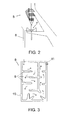
- the outlet (11), as shown in Figure 3 , is provided at the top of the siphon filter (8), from which the water flows towards a receptacle (12) in which a tube oriented in a coil and labyrinth, stair steps, ramps and sinuosities, in which components of organic origin have been deposited, such as fibres (13).
- the inlet (14) is located at the top, and the outlet (15) is located on the opposite side, also in the upper part, after the passage of the water through the labyrinth formed by various elements including the inside the receptacle (12).
- the water passes to a modular centripetal action, decanting and centrifugation modular filter (16), acting as a vortex through the action of the water turbulence, accessing through a funnel or Cone (17), and the water falling onto a propeller (18) located under said outlet of the funnel (17), by activating on its way, the above-mentioned propeller (18) producing the centripetal action or centrifugation of the water against the walls and the bottom of the receptacle, facilitating more decanting and adherence on appropriate films and grids by friction of the sheets which are housed inside.
- the filter (16) is modular and may present different geometric shapes and designs so that it can be implemented to will or convenience, being able to use a single module or several modules, linking them in the way deemed most appropriate and reserving the latter to filter particles between 200 to 800 Microns in size, as convenient. Allowing the system to adapt it-self to the characteristics of the waters of the location and the characteristics of the terrain, with minimal impact on it, It can also be positioned in parallel, in a line or overlapping, provided that the water flow is produced by gravity from one module to the other.
- corresponding grids (24) have been provided with large to small openings, with the particularity that in the interior of the recipient/container (21) a mass of vegetable carbon and/or activated carbon (25) which guarantees a high degree of filtration after the water pushes the carbon vertically and passes through it, so that the buoyancy effect of the carbon, allows the pieces of the same to adjust themselves in order to conform and maximize the filter action from the base.
- one or more doors (26) have been installed with airtight seals that help in cleaning the recipient/container (21) and replace the mass of carbon (25) to convenience. Also supported in the structure, an internal ladder and another steel ladder, installed outdoors tied to the structure to facilitate the work of verifying and maintaining of the system.
- recollection receptacle which is totally or partially waterproofed, the base, for example, is covered with compacted clay, rubber, mortar, asphalt fabrics, etc., individually or combined, so that the inside of said recollection receptacle (27) will have walls, enclosures and deposits of polymers and filled with neutral absorbent materials that retain and release the water absorbed by gravity in a slow process.
- a birth or permanent water source (28) is fed, which first comprises a deposit (29) with an outlet pipe (30), which feeds four successive deposits (31, 32, 33 and 33b), which can be closed or open according to the needs and are connected through their base, with a communicating vases system, so the water maintains the same level but only flows towards the outlet through the lowest level.
- the deposit (31) is the place where the water jumps up and helps to create a cool area by natural evaporation, while deposit (32) is a receptacle of a larger capacity and with the same purpose, more oriented to animals, due to this fact, it is located more distant from the outlet pipe (30), and regulated by two compartments: one external and open compartment and one closed compartment which will produce water, keeping it under the best conditions.
- the deposit (33) has a large capacity and inside it includes two or more buoys, as convenient and attached to two levers that allow the operation of the gear shafts which rotate a gear system in a transmission.
- Another deposit (33) is fed from another smaller (33b) deposit installed inside the auto-reloading tower (36).
- This system manages to carry out the opening or closing of the flow volume that comes out of the outlet pipe and an operation of opening or closing of the doors of a heat source (34) which is installed in the auto-reloading tower (36), which re-circulates the water to the deposit (29), so that the water accesses this tower through its base to the smaller reservoir (33b) through pipe (37)as shown in Figure 1 .
- Said auto-reloading tower (34) will have one or more doors that can be of the side slide type doors, vertical or tangential, which will be closed if there is no water in the circuit, and that will open mechanically, gradually and automatically when the buoy of the deposit (33) is in the filling position, elevating the water and making it to circulate, in a rapid evaporation process, operated by solar plates and the added support of concave and convex mirrors plus the timely reflective materials.
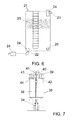
- This water circulates, after starting to boil in the deposit located in the core of the base of the auto-reloading tower (36), in the form of steam through a vertical column (38), in a rapid evaporation process, so that the water steam that is produced, enters a closed deposit (39) in which there is an internal small rotor or impeller (40) located on the top of the tower, which is operated by external winds that rotate another rotor (41).
- This internal rotor is centripetal or centrifuges the water steam towards the walls (43) of the deposit (39), where it will condense into liquid water through thermal shock, due to the admission of colder air on the external walls and the circulation of the air produced by the internal rotor or impeller (40).
- a second birth or natural water source has been provided in this seasonal case (46), which comprises a deposit (49) to which the water enters into the deposit (47), said deposit (47) has an outlet with one outlet for the evacuation by surplus, into the channel for surplus/waste water (6).
- the water passes into the deposit which forms the so-called birth or natural seasonal water source (46), which deposit (49) has a spout pipe (48) from which the water accesses the deposit (50) with a pipe which carries water to a receptacle, so this water can be used for agricultural use or for water for animal drinking.
- the surplus waters from the collection receptacle (27) and the deposit (47), will form a third birth seasonal water source (35), while the water that flows well regulated through those two water sources (28-46), plus both surplus and a portion of the waters from the surplus/waste water channel (6), which has two or more outlets (6a and 6b) is poured into an infiltration ravine (51) under which some previous work of waterproofing the ditches in the ground was made and were filled with different neutral and permeable materials, such as sand and crushed stones of different size according to the reference (52), so that the area of this space will oscillate between four and one hundred times the surface and volume of all the previous complex, with a variable depth between 2 and 20 mts. with respect to the average level between the filtration ravine (51) and the birth or natural water source.
- water eye At the end of those infiltrations a final birth or resurgence, called “water eye", with an outlet (53) located in the lower level of the complete system, from which water will flow through a mixed system, preferably made of siphon, capillarity or gravity.
- a mixed system preferably made of siphon, capillarity or gravity.
- wetland (54) retained by a fence (55) crescent moon shaped, formed by stones of variable size and a height of between 30 and 90 centimetres, which makes the water to converge into an outlet in the form of seasonal creek (56) which will advance toward the nearest natural course.
Landscapes
- Chemical & Material Sciences (AREA)
- Engineering & Computer Science (AREA)
- Life Sciences & Earth Sciences (AREA)
- Chemical Kinetics & Catalysis (AREA)
- Environmental & Geological Engineering (AREA)
- Hydrology & Water Resources (AREA)
- Water Supply & Treatment (AREA)
- Health & Medical Sciences (AREA)
- Organic Chemistry (AREA)
- Analytical Chemistry (AREA)
- Public Health (AREA)
- Sustainable Energy (AREA)
- Sustainable Development (AREA)
- Toxicology (AREA)
- Mechanical Engineering (AREA)
- Water Treatment By Sorption (AREA)
- Seasonings (AREA)
- Cleaning Or Clearing Of The Surface Of Open Water (AREA)
- Cyclones (AREA)
- Road Paving Structures (AREA)
- Materials Applied To Surfaces To Minimize Adherence Of Mist Or Water (AREA)
- Heat Treatment Of Water, Waste Water Or Sewage (AREA)
Applications Claiming Priority (2)
| Application Number | Priority Date | Filing Date | Title |
|---|---|---|---|
| ES201231697A ES2403128B1 (es) | 2012-11-07 | 2012-11-07 | Sistema para el aprovechamiento de las aguas de las precipitaciones para crear nacimientos o manantiales de aguas permanentes y estacionales |
| PCT/ES2013/070768 WO2014072559A1 (fr) | 2012-11-07 | 2013-11-07 | Système permettant d'utiliser les eaux de précipitation pour créer des sources d'eau permanentes et saisonnières |
Publications (2)
| Publication Number | Publication Date |
|---|---|
| EP2918736A1 true EP2918736A1 (fr) | 2015-09-16 |
| EP2918736A4 EP2918736A4 (fr) | 2016-09-14 |
Family
ID=48470450
Family Applications (1)
| Application Number | Title | Priority Date | Filing Date |
|---|---|---|---|
| EP13853345.0A Withdrawn EP2918736A4 (fr) | 2012-11-07 | 2013-11-07 | Système permettant d'utiliser les eaux de précipitation pour créer des sources d'eau permanentes et saisonnières |
Country Status (11)
| Country | Link |
|---|---|
| US (1) | US20150283476A1 (fr) |
| EP (1) | EP2918736A4 (fr) |
| CN (1) | CN104903520A (fr) |
| CL (1) | CL2015001119A1 (fr) |
| ES (1) | ES2403128B1 (fr) |
| IL (1) | IL238659A (fr) |
| MA (1) | MA38109B1 (fr) |
| MX (1) | MX2015005521A (fr) |
| PE (1) | PE20151151A1 (fr) |
| WO (1) | WO2014072559A1 (fr) |
| ZA (1) | ZA201504063B (fr) |
Families Citing this family (9)
| Publication number | Priority date | Publication date | Assignee | Title |
|---|---|---|---|---|
| CN107098476B (zh) * | 2017-05-25 | 2020-06-12 | 河海大学 | 一种应用于生活污水及低污染水的抗堵塞人工湿地系统 |
| CN111035992A (zh) * | 2019-12-24 | 2020-04-21 | 天津显硕科技有限公司 | 一种环保节能型蓝莓种植用环水装置 |
| CN111643933A (zh) * | 2020-06-10 | 2020-09-11 | 国电银河水务股份有限公司 | 一种曝气式斜板沉淀池 |
| CN111847536A (zh) * | 2020-06-28 | 2020-10-30 | 南京信息工程大学 | 一种分散式初雨净化系统和净化填料的制备方法 |
| CN113429000B (zh) * | 2021-05-26 | 2022-05-27 | 济南一建集团有限公司 | 一种绿色建筑楼顶废水初步处理设备 |
| CN113800679B (zh) * | 2021-09-23 | 2023-08-08 | 温州市丰源水利水电工程有限公司 | 水资源管理用水质处理系统及其施工方法 |
| CN113818518B (zh) * | 2021-10-07 | 2023-06-13 | 旭升建设有限公司 | 一种具有截污清洁功能的防堵分流式城市雨水蓄积装置 |
| CN113737888B (zh) * | 2021-10-08 | 2023-06-23 | 杭州迎绿市政园林工程有限公司 | 一种人工湿地雨水净化回用装置及其使用方法 |
| CN115045234B (zh) * | 2022-07-30 | 2024-06-14 | 浙江宇尧建设有限公司 | 一种避免雨水囤积的水利工程用护坡 |
Family Cites Families (10)
| Publication number | Priority date | Publication date | Assignee | Title |
|---|---|---|---|---|
| US7658857B2 (en) * | 2008-01-08 | 2010-02-09 | Todd Wacome | Treating runoff |
| CN101649635B (zh) * | 2009-09-14 | 2010-11-10 | 哈尔滨工业大学 | 单栋多层建筑物的中水回收再利用系统 |
| CN201785800U (zh) * | 2009-10-10 | 2011-04-06 | 周如和 | 雨水河水地下水自来水联合采用装置 |
| CN201517205U (zh) * | 2009-11-07 | 2010-06-30 | 中国科学院水利部成都山地灾害与环境研究所 | 一种高山天然径流利用系统 |
| DE102009053027A1 (de) * | 2009-11-12 | 2011-05-19 | Aquaroc E.K. | Regenwasser-Sicker/Rückhalte-System |
| CN201558584U (zh) * | 2009-11-16 | 2010-08-25 | 柳晓涓 | 雨水收集过滤箱 |
| KR101005589B1 (ko) * | 2010-05-11 | 2011-01-06 | 이성우 | 하천의 법면에 설치되는 친환경 초기우수처리 시스템 |
| IT1403682B1 (it) * | 2011-02-07 | 2013-10-31 | Isea S P A | Impianto per la depurazione ed il riutilizzo di acque grigie con disinfezione ad ozono. |
| CN202265856U (zh) * | 2011-09-23 | 2012-06-06 | 柯依坤 | 空中纳水篷 |
| CN202450712U (zh) * | 2012-01-16 | 2012-09-26 | 陆善祥 | 雨水收集处理利用装置 |
-
2012
- 2012-11-07 ES ES201231697A patent/ES2403128B1/es not_active Expired - Fee Related
-
2013
- 2013-11-07 EP EP13853345.0A patent/EP2918736A4/fr not_active Withdrawn
- 2013-11-07 US US14/441,300 patent/US20150283476A1/en not_active Abandoned
- 2013-11-07 CN CN201380058228.XA patent/CN104903520A/zh active Pending
- 2013-11-07 MX MX2015005521A patent/MX2015005521A/es unknown
- 2013-11-07 WO PCT/ES2013/070768 patent/WO2014072559A1/fr not_active Ceased
- 2013-11-07 MA MA38109A patent/MA38109B1/fr unknown
- 2013-11-07 PE PE2015000587A patent/PE20151151A1/es not_active Application Discontinuation
-
2015
- 2015-04-29 CL CL2015001119A patent/CL2015001119A1/es unknown
- 2015-05-06 IL IL238659A patent/IL238659A/en not_active IP Right Cessation
- 2015-06-05 ZA ZA2015/04063A patent/ZA201504063B/en unknown
Also Published As
| Publication number | Publication date |
|---|---|
| CN104903520A (zh) | 2015-09-09 |
| MA38109B1 (fr) | 2017-09-29 |
| CL2015001119A1 (es) | 2015-10-23 |
| WO2014072559A1 (fr) | 2014-05-15 |
| ES2403128A1 (es) | 2013-05-14 |
| IL238659A0 (en) | 2015-06-30 |
| MX2015005521A (es) | 2016-01-12 |
| MA38109A1 (fr) | 2017-01-31 |
| EP2918736A4 (fr) | 2016-09-14 |
| ES2403128B1 (es) | 2013-09-18 |
| IL238659A (en) | 2016-08-31 |
| US20150283476A1 (en) | 2015-10-08 |
| PE20151151A1 (es) | 2015-09-05 |
| ZA201504063B (en) | 2016-04-28 |
Similar Documents
| Publication | Publication Date | Title |
|---|---|---|
| EP2918736A1 (fr) | Système permettant d'utiliser les eaux de précipitation pour créer des sources d'eau permanentes et saisonnières | |
| US20130180903A1 (en) | Stormwater filtration systems and related methods | |
| CN106193247A (zh) | 用于海绵城市的一体化雨水系统及其施工方法 | |
| KR101927603B1 (ko) | 자연유하식 산지 빗물 집수 시스템 | |
| ES2371695A1 (es) | Estación hidráulica de recuperación, de gestión y de distribución de las aguas pluviales. | |
| CN104003574A (zh) | 一种适用于农田排水沟渠的迷宫式生态净化池 | |
| CN209082291U (zh) | 一种海绵城市道路排水系统 | |
| CN212670759U (zh) | 一种坡面植草沟 | |
| CN205204913U (zh) | 用于初期雨水收集回用的隐形生态滤池系统 | |
| CN108990452B (zh) | 一种耦合潜水层咸淡水替换及淋洗脱盐装置 | |
| KR101370481B1 (ko) | 인공함양용 필터링 시스템 및 인공함양용 필터링 시스템 세척방법 | |
| CN205242598U (zh) | 一种在线式生态植被渗透浅沟 | |
| KR101404215B1 (ko) | 빗물저장시설 및 이를 포함하는 수생식물을 이용한 정화시스템 | |
| KR20190020455A (ko) | 빗물 집수판 및 이를 이용한 집수장치 | |
| CN205875352U (zh) | 一种一体化坡面雨水沉砂和收集装置 | |
| CN113179929A (zh) | 一种用于园林雨水的收集及循环利用系统 | |
| US20130180929A1 (en) | Stormwater filtration systems and related methods | |
| CN119711523A (zh) | 一种绿色装配阶梯式景观边坡支护 | |
| SE511200C2 (sv) | Anordning och förfarande vid ett avloppssystem där huvudavloppsledningen är utformad som en sluten ringledning | |
| WO2008035964A1 (fr) | Emplacement pour la pousse, procédé et support | |
| ES2956360T3 (es) | Dispositivo de agua para la colonización y/o alojamiento al menos temporal de anfibios | |
| KR20150068885A (ko) | 빗물저장시설 및 이를 포함하는 수생식물을 이용한 정화시스템 | |
| CN105417714A (zh) | 山地河流生态护岸雨水净化处理系统 | |
| CN214614445U (zh) | 一种用于下凹绿地的排水结构 | |
| RU2770692C1 (ru) | Способ предупреждения поступления поверхностных вод с территории площадных и точечных источников загрязнения |
Legal Events
| Date | Code | Title | Description |
|---|---|---|---|
| PUAI | Public reference made under article 153(3) epc to a published international application that has entered the european phase |
Free format text: ORIGINAL CODE: 0009012 |
|
| 17P | Request for examination filed |
Effective date: 20150506 |
|
| AK | Designated contracting states |
Kind code of ref document: A1 Designated state(s): AL AT BE BG CH CY CZ DE DK EE ES FI FR GB GR HR HU IE IS IT LI LT LU LV MC MK MT NL NO PL PT RO RS SE SI SK SM TR |
|
| AX | Request for extension of the european patent |
Extension state: BA ME |
|
| DAX | Request for extension of the european patent (deleted) | ||
| RA4 | Supplementary search report drawn up and despatched (corrected) |
Effective date: 20160818 |
|
| RIC1 | Information provided on ipc code assigned before grant |
Ipc: E03B 3/04 20060101AFI20160811BHEP |
|
| GRAP | Despatch of communication of intention to grant a patent |
Free format text: ORIGINAL CODE: EPIDOSNIGR1 |
|
| INTG | Intention to grant announced |
Effective date: 20190103 |
|
| RIN1 | Information on inventor provided before grant (corrected) |
Inventor name: VALERO VALDELVIRA, JUAN |
|
| STAA | Information on the status of an ep patent application or granted ep patent |
Free format text: STATUS: THE APPLICATION IS DEEMED TO BE WITHDRAWN |
|
| 18D | Application deemed to be withdrawn |
Effective date: 20190514 |