EP2918791A1 - Zur Führung eines Heißgases vorgesehene Vorrichtung sowie Verwendung von Formsand - Google Patents
Zur Führung eines Heißgases vorgesehene Vorrichtung sowie Verwendung von Formsand Download PDFInfo
- Publication number
- EP2918791A1 EP2918791A1 EP14159352.5A EP14159352A EP2918791A1 EP 2918791 A1 EP2918791 A1 EP 2918791A1 EP 14159352 A EP14159352 A EP 14159352A EP 2918791 A1 EP2918791 A1 EP 2918791A1
- Authority
- EP
- European Patent Office
- Prior art keywords
- gas
- flow path
- molding sand
- gas turbine
- hot
- Prior art date
- Legal status (The legal status is an assumption and is not a legal conclusion. Google has not performed a legal analysis and makes no representation as to the accuracy of the status listed.)
- Withdrawn
Links
- 239000004576 sand Substances 0.000 title claims description 9
- 238000000465 moulding Methods 0.000 title 1
- 239000003110 molding sand Substances 0.000 claims abstract description 32
- 239000000463 material Substances 0.000 claims description 5
- 239000000758 substrate Substances 0.000 abstract description 2
- VYPSYNLAJGMNEJ-UHFFFAOYSA-N Silicium dioxide Chemical compound O=[Si]=O VYPSYNLAJGMNEJ-UHFFFAOYSA-N 0.000 description 8
- 229910052751 metal Inorganic materials 0.000 description 8
- 239000002184 metal Substances 0.000 description 8
- 230000003628 erosive effect Effects 0.000 description 5
- 239000010410 layer Substances 0.000 description 5
- 239000011230 binding agent Substances 0.000 description 4
- 238000005266 casting Methods 0.000 description 3
- 238000004519 manufacturing process Methods 0.000 description 3
- 239000011241 protective layer Substances 0.000 description 3
- 238000004513 sizing Methods 0.000 description 3
- 230000007704 transition Effects 0.000 description 3
- 239000006004 Quartz sand Substances 0.000 description 2
- 239000000956 alloy Substances 0.000 description 2
- 229910045601 alloy Inorganic materials 0.000 description 2
- 238000010276 construction Methods 0.000 description 2
- 239000007788 liquid Substances 0.000 description 2
- 150000002739 metals Chemical class 0.000 description 2
- 239000000203 mixture Substances 0.000 description 2
- 238000011084 recovery Methods 0.000 description 2
- 239000000126 substance Substances 0.000 description 2
- 239000005995 Aluminium silicate Substances 0.000 description 1
- 235000012211 aluminium silicate Nutrition 0.000 description 1
- 235000012216 bentonite Nutrition 0.000 description 1
- 239000000919 ceramic Substances 0.000 description 1
- 239000004927 clay Substances 0.000 description 1
- 239000011248 coating agent Substances 0.000 description 1
- 238000000576 coating method Methods 0.000 description 1
- 230000006835 compression Effects 0.000 description 1
- 238000007906 compression Methods 0.000 description 1
- 238000007596 consolidation process Methods 0.000 description 1
- 230000000694 effects Effects 0.000 description 1
- 239000012943 hotmelt Substances 0.000 description 1
- 229910052900 illite Inorganic materials 0.000 description 1
- 229910052500 inorganic mineral Inorganic materials 0.000 description 1
- 238000009434 installation Methods 0.000 description 1
- NLYAJNPCOHFWQQ-UHFFFAOYSA-N kaolin Chemical compound O.O.O=[Al]O[Si](=O)O[Si](=O)O[Al]=O NLYAJNPCOHFWQQ-UHFFFAOYSA-N 0.000 description 1
- 238000002844 melting Methods 0.000 description 1
- 230000008018 melting Effects 0.000 description 1
- 238000000034 method Methods 0.000 description 1
- 239000011707 mineral Substances 0.000 description 1
- VGIBGUSAECPPNB-UHFFFAOYSA-L nonaaluminum;magnesium;tripotassium;1,3-dioxido-2,4,5-trioxa-1,3-disilabicyclo[1.1.1]pentane;iron(2+);oxygen(2-);fluoride;hydroxide Chemical compound [OH-].[O-2].[O-2].[O-2].[O-2].[O-2].[F-].[Mg+2].[Al+3].[Al+3].[Al+3].[Al+3].[Al+3].[Al+3].[Al+3].[Al+3].[Al+3].[K+].[K+].[K+].[Fe+2].O1[Si]2([O-])O[Si]1([O-])O2.O1[Si]2([O-])O[Si]1([O-])O2.O1[Si]2([O-])O[Si]1([O-])O2.O1[Si]2([O-])O[Si]1([O-])O2.O1[Si]2([O-])O[Si]1([O-])O2.O1[Si]2([O-])O[Si]1([O-])O2.O1[Si]2([O-])O[Si]1([O-])O2 VGIBGUSAECPPNB-UHFFFAOYSA-L 0.000 description 1
- 230000000149 penetrating effect Effects 0.000 description 1
- 239000002002 slurry Substances 0.000 description 1
Images
Classifications
-
- F—MECHANICAL ENGINEERING; LIGHTING; HEATING; WEAPONS; BLASTING
- F01—MACHINES OR ENGINES IN GENERAL; ENGINE PLANTS IN GENERAL; STEAM ENGINES
- F01D—NON-POSITIVE DISPLACEMENT MACHINES OR ENGINES, e.g. STEAM TURBINES
- F01D25/00—Component parts, details, or accessories, not provided for in, or of interest apart from, other groups
- F01D25/28—Supporting or mounting arrangements, e.g. for turbine casing
- F01D25/285—Temporary support structures, e.g. for testing, assembling, installing, repairing; Assembly methods using such structures
-
- F—MECHANICAL ENGINEERING; LIGHTING; HEATING; WEAPONS; BLASTING
- F01—MACHINES OR ENGINES IN GENERAL; ENGINE PLANTS IN GENERAL; STEAM ENGINES
- F01D—NON-POSITIVE DISPLACEMENT MACHINES OR ENGINES, e.g. STEAM TURBINES
- F01D25/00—Component parts, details, or accessories, not provided for in, or of interest apart from, other groups
- F01D25/30—Exhaust heads, chambers, or the like
-
- F—MECHANICAL ENGINEERING; LIGHTING; HEATING; WEAPONS; BLASTING
- F05—INDEXING SCHEMES RELATING TO ENGINES OR PUMPS IN VARIOUS SUBCLASSES OF CLASSES F01-F04
- F05D—INDEXING SCHEME FOR ASPECTS RELATING TO NON-POSITIVE-DISPLACEMENT MACHINES OR ENGINES, GAS-TURBINES OR JET-PROPULSION PLANTS
- F05D2230/00—Manufacture
- F05D2230/90—Coating; Surface treatment
Definitions
- the invention relates to a device for guiding a hot gas, wherein the device comprises at least one wall for at least partially limiting a flow path through which hot gas can flow. Furthermore, the invention relates to the use of molding sand.
- the hot gas flowing in the interior of the gas turbine is conducted as exhaust gas via further channels to other devices.
- the other devices may be, for example, an exhaust stack or a heat recovery steam generator, in the latter, the heat energy present in the exhaust gas is converted into superheated steam for energy production.
- channels made of metal channels are used, which are then configured, for example, as an exhaust gas diffuser or exhaust pipe.
- care is taken to ensure that the material used can permanently withstand the temperatures of the hot or exhaust gas.
- the exhaust gas temperatures of a stationary gas turbine are today on the order of about 650 ° C and beyond. Consequently, relatively temperature-resistant metals or alloys are needed, which is relatively expensive.
- the high exhaust gas temperatures cause the metallic components to expand during operation, so that, in particular, the transition points of the exhaust gas ducts to other devices are designed to be tolerant of expansion and, if necessary, to be sealed.
- the strain-tolerant installation and attachment of the exhaust ducts and the Seals therefore require expensive constructions, which is undesirable.
- gas turbines are manufactured and operated in different sizes and performance classes. Some manufacturers of such gas turbines have a test and test stand to test and test these gas turbines prior to their delivery. It is also known to test prototypes of gas turbines before sale or delivery. In the case of a change from one gas turbine to another type, therefore, the ducts carrying the exhaust gas must be adapted to the respective geometric construction of the gas turbine to be tested next in the test and test bench in the test and test bench. These adjustments may prove comparatively expensive when both the exhaust diffuser and the exhaust pipe need to be changed for each gas turbine to be re-tested. However, since the test operation is always limited in time, there is a desire to keep the expenses for adapting the exhaust pipes both constructive and cost as low as possible.
- the object of the invention is therefore to provide a device provided for guiding a hot or exhaust gas, which on the one hand is comparatively simple to construct and, on the other hand, is also inexpensive.
- the object directed to the device is achieved by a device for guiding a hot or exhaust gas, wherein the at least one wall of this device is at least partially formed from molding sand.
- molding sand is proposed as a (basic) material of a wall of a hot or exhaust gas-conducting housing component for a gas turbine, an exhaust gas diffuser for a gas turbine and / or an exhaust pipe for a gas turbine.
- the invention is based on the recognition that the requirements for the durability and service life of said hot or exhaust gas-conducting devices in a test and test stand are significantly lower than in a commercial application in which the said devices are to be operated error-free and probably maintenance-free for years.
- the invention solves the matter of course that hot gas components must be made of metal or a temperature-resistant alloy in principle.
- the foundry sand used in foundries for the production of lost molds can be used to form the wall, which limits the flow space of the hot or exhaust gas and thus resists the flow forces occurring in the flow path .
- this foundry sand is exposed to temperatures far above the melting point of metals. Consequently, this is also sufficiently temperature resistant for the new use.
- this is also dimensionally stable, since this must withstand the mechanical loads during the filling of the hot melt in the mold when casting large-sized parts such as church bells or an outer casing of a gas or steam turbine.
- the molding sand is also suitable for the use according to the invention.
- this shape is geometrically comparatively simple: approximately cylindrical or conical or frustoconical, depending on the required flow path shape of the device.
- the invention provides that the device according to the invention is only used for a limited period of time, namely for the duration of the test and test operation of the gas turbine. Nevertheless, it is not excluded that the device according to the invention can also be used in commercially used devices, whose operating time is much longer than the test and test operation.
- Another advantage of the invention is that due to the high density of the molding sand, this sound-insulating effect at the same time, without further components are required for it. Furthermore, the molding sand is reusable, which is particularly advantageous for use in a test and test stand. The purchase of new molding sand for the design of a new hot or exhaust gas device can be kept relatively small.
- natural sand or a quartz sand could be used as foundry sand.
- a synthetic or natural binder is also included in the foundry sand.
- the mineralogy of the binder can be based on bentonites and other mineral components.
- clay-based binders may also be used, for example, illite and kaolin, but also smectites.
- the surface of the wall of molding sand facing the flow space of the hot gas is at least partially, preferably completely covered with a protective layer which is more resistant to erosion.
- the layer thus extends the life of the device, as it is erosion resistant than the molding sand itself.
- the layer of foundry sand similar to molds, could be applied to said area in the so-called “slurry” process, which is called “sizing” in casting molds.
- slurry which is called "sizing” in casting molds.
- the degree of strength of the layer should be comparatively high, so that the erosion losses during use are particularly low.
- liquids are available that in The composition are relatively complex, but still have the highest degree of consolidation.
- the wall has at least one non-flow-limiting side on which a preferably metallic shell is provided as a shell for the molding sand or as a part of the shell.
- a preferably metallic shell is provided as a shell for the molding sand or as a part of the shell.
- This sheath protects the molding sand from accidental and unwanted damage to its outside, which maintains the integrity of the device.
- the sheath can also be reinforced inside or outside with stiffening ribs or struts.
- the flow path comprises an inflow-side opening and an outflow-side opening facing the inflow-side opening, the contours of the two openings being different. Consequently, the contour of the flow path changes along its longitudinal extension, so that the device is designed quasi as a transition piece. Such transition pieces are often very difficult to manufacture from metal, but this is much easier and less expensive when using molding sand.
- the device is equipped as a housing component of a gas turbine or exhaust gas diffuser of a gas turbine or exhaust pipe of a gas turbine.
- a housing component of a gas turbine is to be understood as such, which is structurally still to be assigned to the gas turbine itself, but is provided for conducting the hot or exhaust gas of the gas turbine.
- the exhaust gas diffuser of a gas turbine and the exhaust pipe of a gas turbine are structurally separate from the gas turbine to consider separately.
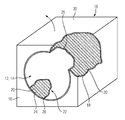
- the single figure shows a three-dimensional sectional drawing of a device 10 for guiding a hot gas.
- the device 10 is substantially cube-shaped in the embodiment shown. It can of course also be cuboid or cylindrical.
- the device 10 comprises according to the embodiment shown, a shell 18 which is made of a simple metallic wall.
- the shell 18 serves only as a shell for molding sand 20.
- two opposing openings 14, 16 are provided, which are fluidically connected to each other.
- the flow path 22 extending between the two openings 14, 16 serves to guide a hot or exhaust gas from one opening 14 to the other opening 16.
- a hole 12 penetrating the device 10 is present.
- the inflow-side opening 14 may have a different contour than the outflow-side opening 16. This embodiment is particularly suitable when the device 10 is to connect a cross-sectionally circular, downstream end of the gas turbine to a cross-sectionally square inflow-side end of a heat recovery steam generator.
- the layer may also be a ceramic protective layer.
- This shell 18 may be made of a less temperature resistant material than the molding sand 20, since 18 ambient temperatures prevail during operation of the device 10 on the outside of the shell.
- the shell 18 may be bricked or made of metal.
- the shell 18 is open at the locations of the later inflow and outflow openings 14, 16.
- a flow path 22 representing the core is used, which simultaneously closes the openings 14, 16.
- molding sand 20 is filled into the device 10 from above into the casing 18 when the lid 30 is open. A gradual filling of molding sand 20 with intermediate compression of the hitherto filled molding sand 20 is also possible.
- the lid 30 is subsequently closed and the core representing the flow path 22 is removed.
- the hole 12 is then completely surrounded by the molding sand 20, which then constitutes a wall bounding the flow path 22.
- the surface 24 of the molding sand, which is thus facing the flow path 22 is sized, that is, a sizing liquid or paste is applied to the surface 24, which then becomes an erosion protective layer permanent part of the device 10.
- the device 10 it is also conceivable to design the device 10 to be divisible in half, so that the device 10 then comprises two walls essentially consisting of molding sand 20 which together define the flow path 22.
- the device 10 may be, for example, a diffuser for hot or exhaust gas.
- the invention relates to a flow path 22 for the hot gas or exhaust gas of a gas turbine comprehensive device 10, which is relatively simple and inexpensive and can be produced in a short time and possibly designed for a comparatively short service life.
- the device 10 essentially consists of molding sand 20, and the molding sand 20 limits the flow path 22 or serves as a substrate resisting the flow forces of a layer 26 delimiting the flow path 22.
Landscapes
- Engineering & Computer Science (AREA)
- Mechanical Engineering (AREA)
- General Engineering & Computer Science (AREA)
- Exhaust Silencers (AREA)
Abstract
Die Erfindung betrifft eine einen Strömungspfad (22) für das Heißgas oder Abgas einer Gasturbine umfassende Vorrichtung (10), welche sich vergleichsweise einfach und kostengünstig sowie in kurzer Zeit fertigen lässt und ggf. für eine vergleichsweise kurze Betriebsdauer ausgelegt ist. Um dies zu erreichen wird vorgeschlagen, dass die Vorrichtung (10) im Wesentlichen aus Formsand (20) gebildet ist und der Formsand (20) den Strömungspfad (22) begrenzt oder als Substrat einer den Strömungspfad (22) begrenzenden Schicht (26) dient.
Description
- Die Erfindung betrifft eine Vorrichtung zur Führung eines Heißgases, wobei die Vorrichtung zumindest eine Wand zur zumindest teilweisen Begrenzung eines von Heißgas durchströmbaren Strömungspfades umfasst. Weiter betrifft die Erfindung die Verwendung von Formsand.
- Bei zur Erzeugung von elektrischer Energie stationär eingesetzten Gasturbinen ist es bekannt, dass das im Inneren der Gasturbine strömende Heißgas nach seiner Entspannung in der Turbineneinheit als Abgas über weitere Kanäle zu anderen Einrichtungen geführt wird. Die anderen Einrichtungen können beispielsweise ein Abgaskamin oder auch ein Abhitzedampferzeuger sein, wobei in letzterem die im Abgas vorhandene Wärmeenergie in Heißdampf zur Energieerzeugung umgewandelt wird.
- Bei der Leitung des Heißgases bzw. des Abgases stromab der Gasturbine werden bisher aus Metall gebildete Kanäle verwendet, die dann beispielsweise als Abgasdiffusor oder als Abgasleitung ausgestaltet sind. Bei der Verwendung von Metall als Material der Kanäle wird darauf geachtet, dass das verwendete Material den Temperaturen des Heiß- bzw. Abgases dauerhaft standhalten kann. Die Abgastemperaturen einer stationären Gasturbine liegen heutzutage in der Größenordnung von etwa 650°C und darüber hinaus. Mithin werden vergleichsweise temperaturfeste Metalle bzw. Legierungen benötigt, was vergleichsweise kostenintensiv ist. Weiter führen die hohen Abgastemperaturen dazu, dass die metallischen Bauteile sich im Betrieb ausdehnen, so dass insbesondere die Übergangstellen der Abgas-Kanäle zu anderen Vorrichtungen dehnungstolerant ausgebildet und ggf. abzudichten sind. Die dehnungstolerante Aufstellung und Befestigung der Abgas-Kanäle sowie die Abdichtungen erfordern mithin aufwändige Konstruktionen, was ungewünscht ist.
- Gleichzeitig ist es bekannt, dass Gasturbinen in unterschiedlichen Größen und Leistungsklassen hergestellt und betrieben werden. Einige Hersteller derartiger Gasturbinen besitzen einen Prüf- und Teststand, um diese Gasturbinen vor ihrer Auslieferung zu erproben und zu testen. Auch ist es bekannt, Prototypen von Gasturbinen vor Verkauf bzw. Auslieferung zu testen. Bei einem Wechsel von einer Gasturbine zu einem anderen Typ sind in dem Prüf- und Teststand deswegen die das Abgas führenden Kanäle an die jeweilige geometrische Konstruktion der als nächstes im Prüf- und Teststand zu erprobenden Gasturbine anzupassen. Diese Anpassungsarbeiten können sich als vergleichsweise teuer erweisen, wenn sowohl Abgasdiffusor und Abgasleitung für jede neu zu prüfende Gasturbine geändert werden müssen. Da jedoch der Testbetrieb stets zeitlich begrenzt ist, besteht das Bestreben, die Aufwendungen für die Anpassungen der Abgasleitungen sowohl konstruktiv als auch kostenbezogen möglichst gering zu halten.
- Aufgabe der Erfindung ist daher die Bereitstellung einer zur Führung eines Heiß- oder Abgases vorgesehenen Vorrichtung, die einerseits vergleichsweise einfach konstruktiv zu fertigen und andererseits ebenso preisgünstig ist.
- Erfindungsgemäß wird die auf die Vorrichtung gerichtete Aufgabe durch eine Vorrichtung zur Führung eines Heiß- oder Abgases gelöst, wobei die zumindest eine Wand dieser Vorrichtung zumindest teilweise aus Formsand gebildet ist. Mithin wird die Verwendung von Formsand als (Grund-)Werkstoff einer Wand einer Heiß- oder Abgas leitenden Gehäusekomponente für einer Gasturbine, eines Abgasdiffusors für eine Gasturbine und/oder eine Abgasleitung für eine Gasturbine vorgeschlagen.
- Die Erfindung beruht auf der Erkenntnis, dass die Anforderungen an die Dauerhaftigkeit und Lebensdauer der besagten heißoder abgasführenden Vorrichtungen in einem Prüf- und Teststand wesentlich geringer sind als bei einer kommerziellen Anwendung, bei der die besagten Vorrichtungen über Jahre hinweg fehlerfrei und wohlmöglich wartungsfrei betrieben werden sollen. Gleichzeitig löst sich die Erfindung von der Selbstverständlichkeit, dass heißgasführende Bauteile prinzipiell aus Metall oder einer temperaturfesten Legierung sein müssen.
- Mit der Erfindung wird nun erstmalig vorgeschlagen, dass anstelle von Metall den in Gießereien zur Herstellung von verlorenen Formen benutzte Formsand verwendet werden kann, um die Wand zu bilden, welche den Strömungsraum des Heiß- bzw. Abgases begrenzt und folglich den im Strömungspfad auftretenden Strömungskräften widersteht. Dieser Formsand ist in der ursprünglichen Anwendung Temperaturen ausgesetzt ist, die weit über den Schmelzpunkt von Metallen liegen. Folglich ist dieser auch hinreichend temperaturbeständig für die neue Verwendung. Gleichzeitig ist dieser auch formbeständig, da dieser beim Gießen von großformatigen Teilen wie Kirchenglocken oder einem äußerem Gehäuse einer Gas- oder Dampfturbine auch mechanischen Belastungen während des Einfüllens der heißen Schmelze in die Gießform standhalten muss. Mithin eignet sich der Formsand auch für die erfindungsgemäße Verwendung.
- Zwar wurde der Formsand bisher nur zum Abgießen vergleichsweise detaillierter Formen, wie etwa eine Kirchenglocke oder einem Druckmantel einer Turbine verwendet. Mit der Erfindung wird erstmalig vorgeschlagen, dass diese Form geometrisch vergleichsweise einfach ist: etwa zylindrisch oder konisch bzw. kegelstumpfförmig, je nach der erforderlichen Strömungspfadgestalt der Vorrichtung.
- Ursprünglich sieht die Erfindung vor, dass die erfindungsgemäße Vorrichtung erst mal nur für eine begrenzte Zeitdauer, nämlich für die Zeitdauer des Prüf- und Testbetriebs der Gasturbine, eingesetzt wird. Nichtsdestotrotz ist nicht ausgeschlossen, dass die erfindungsgemäße Vorrichtung auch bei kommerziell genutzten Vorrichtungen verwendet werden können, deren Betriebsdauer weit länger ist als der Prüf- und Testbetrieb.
- Ein weiterer Vorteil der Erfindung ist, dass aufgrund der großen Dichte des Formsands dieser gleichzeitig schallisolierend wirkt, ohne dass weitere Komponenten dafür erforderlich sind. Weiterhin ist der Formsand wiederverwendbar, was insbesondere für die Anwendung in einem Prüf- und Teststand von Vorteil ist. Die Anschaffungsmenge von neuem Formsand zur Gestaltung einer neuen heiß- oder abgasführenden Vorrichtung kann vergleichsweise klein gehalten werden.
- Als Formsand könnte beispielsweise Natursand oder auch ein Quarzsand verwendet werden. Gegebenenfalls ist im Formsand auch ein Binder auf synthetischer oder natürlicher Basis enthalten. Wegen des besonders guten Festigkeitspotenzials und der hohen Oberflächenqualität bietet sich insbesondere die Verbindung eines Hybridbinders mit Quarzsand an. Die Mineralogie des Binders können auf Bentonite und anderen mineralische Komponenten basieren. Dagegen können aber auch auf Ton basierende Binder ggf. verwendet werden, beispielsweise Illit und Kaolin aber auch Smectite.
- Gemäß einer ersten vorteilhaften Weiterbildung ist vorgesehen, dass die dem Strömungsraum des Heißgases zugewandte Fläche der Wand aus Formsand zumindest teilweise, vorzugsweise vollständig mit einer erosionsbeständigeren Schutzschicht überzogen ist. Die Schicht verlängert somit die Lebensdauer der Vorrichtung, da diese erosionsbeständiger ist als der Formsand selber. Die Schicht des Formsandes, könnte ähnlich wie bei Gießformen, im so genannten "Slurry"-Verfahren auf die besagte Fläche aufgebracht werden, was bei Gießformen "Schlichten" genannt wird. Zum Schlichten stehen erfahrungsgemäß unterschiedliche Substanzen bzw. Substanzgemische in unterschiedlichen Konsistenzen bereit. Vorzugsweise sollte der Festigkeitsgrad der Schicht vergleichsweise hoch sein, damit die Erosionsverluste während des Einsatzes besonders gering sind. Insofern bieten sich Flüssigkeiten an, die in der Zusammensetzung vergleichsweise komplex sind, aber dennoch den höchsten Festigungsgrad aufweisen.
- Gemäß einer weiteren vorteilhaften Ausgestaltung weist die Wand zumindest eine dem Strömungsraum nicht begrenzende Seite auf, an welcher eine vorzugsweise metallische Schale als Hülle für den Formsand oder als ein Teil der Hülle vorgesehen ist. Diese Hülle schützt den Formsand vor zufälligen und ungewollten Beschädigungen an seiner Außenseite, was die Integrität der Vorrichtung aufrecht erhält. Die Hülle kann zudem innen oder außen mit Versteifungsrippen oder Streben verstärkt sein.
- Bei einer weiter bevorzugten Ausgestaltung umfasst der Strömungspfad eine einströmseitige Öffnung und eine der einströmseitigen Öffnung gegenüberliegende ausströmseitige Öffnung, wobei die Konturen der beiden Öffnungen unterschiedlich sind. Mithin ändert sich die Kontur des Strömungspfads entlang seiner Längserstreckung, so dass die Vorrichtung quasi als Übergangsstück ausgestaltet ist. Derartige Übergangsstücke sind aus Metall häufig sehr schwierig herzustellen, was aber bei der Verwendung von Formsand wesentlich einfacher und kostengünstiger ist.
- Weiter bevorzugt ist die Vorrichtung als Gehäusekomponente einer Gasturbine oder als Abgasdiffusor einer Gasturbine oder als Abgasleitung einer Gasturbine ausgestattet. Dabei ist unter einer Gehäusekomponente einer Gasturbine eine derartige zu verstehen, die strukturmechanisch noch der Gasturbine selber zuzuordnen ist, jedoch zur Leitung des Heiß- bzw. Abgases der Gasturbine vorgesehen ist. Dagegen sind der Abgasdiffusor einer Gasturbine und die Abgasleitung einer Gasturbine strukturmechanisch von der Gasturbine separat zu betrachten.
- Weitere Vorteile und Merkmale der Erfindung werden anhand eines Ausführungsbeispiels angegeben.
- Es zeigt:
- Figur 1
- zeigt in perspektivischer Darstellung schematisch eine Vorrichtung zur Führung eines Heißgases.
- Die einzige Figur zeigt als dreidimensionale Schnittzeichnung eine Vorrichtung 10 zur Führung eines Heißgases. Die Vorrichtung 10 ist im gezeigten Ausführungsbeispiel im Wesentlichen würfelförmig. Sie kann selbstverständlich auch quaderförmig oder zylindrisch sein.
- Die Vorrichtung 10 umfasst gemäß dem gezeigten Ausführungsbeispiel eine Hülle 18, die aus einer einfachen metallischen Wand gefertigt ist. Die Hülle 18 dient lediglich als Schale für Formsand 20. In der Hülle 18 und im Formsand 20 sind zwei einander gegenüberliegende Öffnungen 14, 16 vorgesehen, die strömungstechnisch miteinander verbunden sind. Der sich zwischen den beiden Öffnungen 14, 16 erstreckende Strömungspfad 22 dient zur Führung eines Heiß- oder Abgases von der einen Öffnung 14 zu der anderen Öffnung 16. Mithin ist ein die Vorrichtung 10 vollständig durchdringendes Loch 12 vorhanden.
- Entlang der Längserstreckung des Strömungspfades 22 kann dieser zylindrisch, konisch oder auch anders ausgestaltet sein. Insbesondere kann die einströmseitige Öffnung 14 eine andere Kontur aufweisen als die ausströmseitige Öffnung 16. Diese Ausgestaltung bietet sich insbesondere dann an, wenn die Vorrichtung 10 ein im Querschnitt kreisförmiges, abströmseitiges Ende der Gasturbine mit einem im Querschnitt quadratischen einströmseitigen Ende eines Abhitzedampferzeugers verbinden soll.
- Auf der dem Strömungspfad 22 zugewandten Fläche 24 des Formsandes 20 ist keine Hülle 18 vorgesehen, sondern eine Beschichtung 26 aufgebracht, die erosionsbeständig ist. Die Schicht ist kann auch eine keramische Schutzschicht sein.
- Zur Herstellung der Vorrichtung 10 ist zuerst eine ggf. mit Streben verstärkte Hülle 18 zu fertigen. Diese Hülle 18 kann aus einem weniger temperaturbeständigen Material als der Formsand 20 gefertigt sein, da während des Betriebs der Vorrichtung 10 an der Außenseite der Hülle 18 Umgebungstemperaturen herrschen. Mithin kann die Hülle 18 gemauert sein oder aus Metall bestehen. Die Hülle 18 ist an den Stellen der späteren Einström- und Ausströmöffnungen 14, 16 geöffnet. In die Hülle 18 wird ein den Strömungspfad 22 repräsentierender Kern eingesetzt, der gleichzeitig die Öffnungen 14, 16 verschließt. Anschließend wird in die Hülle 18 bei geöffnetem Deckel 30 von oben Formsand 20 in die Vorrichtung 10 eingefüllt. Eine schrittweise Einfüllung von Formsand 20 mit zwischenzeitlichem Verpressen des bis dahin eingefüllten Formsandes 20 ist ebenso möglich. Nach dem vollständigen Befüllen der Hülle 18 mit Formsand 20 wird anschließend der Deckel 30 geschlossen und der den Strömungspfad 22 repräsentierende Kern entfernt. Das Loch 12 ist dann vollständig vom Formsand 20 umgeben, der dann eine den Strömungspfad 22 begrenzende Wand darstellt. Danach wird die Oberfläche 24 des Formsandes, die dem Strömungspfad 22 mithin zugewandt ist, geschlichtet, das heißt, es wird eine Schlichtflüssigkeit oder -paste auf die Oberfläche 24 aufgetragen, die dann als Erosionsschutzschicht dauerhafter Teil der Vorrichtung 10 wird.
- Selbstverständlich ist es auch denkbar die Vorrichtung 10 hälftig teilbar auszugestalten, so dass die Vorrichtung 10 dann zwei im wesentlichen aus Formsand 20 bestehenden Wände umfasst, die gemeinsam den Strömungspfad 22 begrenzen.
- Ist der Strömungspfad 22 kegelstumpfförmig ausgestaltet ist, kann es sich bei der Vorrichtung 10 beispielsweise um einen Diffusor für Heiß- bzw. Abgas handeln.
- Insgesamt betrifft die Erfindung eine einen Strömungspfad 22 für das Heißgas oder Abgas einer Gasturbine umfassende Vorrichtung 10, welche sich vergleichsweise einfach und kostengünstig sowie in kurzer Zeit fertigen lässt und ggf. für eine vergleichsweise kurze Betriebsdauer ausgelegt ist. Um dies zu erreichen wird vorgeschlagen, dass die Vorrichtung 10 im Wesentlichen aus Formsand 20 besteht, und der Formsand 20 den Strömungspfad 22 begrenzt oder als den Strömungskräften widerstehendes Substrat einer den Strömungspfad 22 begrenzenden Schicht 26 dient.
Claims (9)
- Zur Führung eines Heißgases vorgesehene Vorrichtung (10),
wobei die Vorrichtung (10) zumindest eine Wand zur zumindest teilweisen Begrenzung eines von dem Heißgas durchströmbaren Strömungspfades (22) umfasst,
dadurch gekennzeichnet, dass
die zumindest eine Wand zumindest teilweise aus Formsand (20) gebildet ist. - Vorrichtung (10) nach Anspruch 1,
bei dem die dem Strömungspfad (22) des Heißgases zugewandte Fläche (24) der Wand aus Formsand (20) zumindest teilweise, vorzugsweise vollständig mit einer Schicht (26) überzogen ist. - Vorrichtung (10) nach Anspruch 1 oder 2,
bei der die Wand zumindest eine dem Strömungspfad (22) nicht begrenzende Seite aufweist, an welcher eine vorzugsweise metallische Schale als Hülle (18) für den Formsand (20) oder als ein Teil der Hülle (18) vorgesehen ist. - Vorrichtung (10) nach einem der Ansprüche 1, 2 oder 3, deren Strömungspfad (22) eine einströmseitige Öffnung (14) und eine der einströmseitigen Öffnung (14) gegenüberliegende ausströmseitige Öffnung (16) umfasst,
wobei die Konturen der beiden Öffnungen (14, 16) unterschiedlich sind. - Vorrichtung (10) nach einem der Ansprüche 1 bis 4, ausgestaltet als Gehäusekomponente einer Gasturbine.
- Vorrichtung (10) nach einem der Ansprüche 1 bis 4, ausgestaltet als Abgasdiffusor einer Gasturbine.
- Vorrichtung (10) nach einem der Ansprüche 1 bis 4, ausgestaltet als Abgasleitung einer Gasturbine.
- Verwendung von Formsand (20) als Werkstoff einer Wanda) einer für eine Gasturbine vorgesehenen, heiß- oder abgasleitenden Gehäusekomponente,b) eines für eine Gasturbine vorgesehenen Abgasdiffusors oderc) einer für eine Gasturbine vorgesehene Abgasleitung.
- Verwendung von Formsand (20) nach Anspruch 8,
bei der zumindest ein Teil einer des Strömungspfads (22) eines Heißgases zugewandten Fläche (24) des Formsandes (20) zumindest teilweise, vorzugsweise vollständig mit einer Schicht (26) überzogen ist.
Priority Applications (2)
| Application Number | Priority Date | Filing Date | Title |
|---|---|---|---|
| EP14159352.5A EP2918791A1 (de) | 2014-03-13 | 2014-03-13 | Zur Führung eines Heißgases vorgesehene Vorrichtung sowie Verwendung von Formsand |
| PCT/EP2015/054350 WO2015135789A1 (de) | 2014-03-13 | 2015-03-03 | Zur führung eines heissgases vorgesehene vorrichtung sowie verwendung von formsand |
Applications Claiming Priority (1)
| Application Number | Priority Date | Filing Date | Title |
|---|---|---|---|
| EP14159352.5A EP2918791A1 (de) | 2014-03-13 | 2014-03-13 | Zur Führung eines Heißgases vorgesehene Vorrichtung sowie Verwendung von Formsand |
Publications (1)
| Publication Number | Publication Date |
|---|---|
| EP2918791A1 true EP2918791A1 (de) | 2015-09-16 |
Family
ID=50272440
Family Applications (1)
| Application Number | Title | Priority Date | Filing Date |
|---|---|---|---|
| EP14159352.5A Withdrawn EP2918791A1 (de) | 2014-03-13 | 2014-03-13 | Zur Führung eines Heißgases vorgesehene Vorrichtung sowie Verwendung von Formsand |
Country Status (2)
| Country | Link |
|---|---|
| EP (1) | EP2918791A1 (de) |
| WO (1) | WO2015135789A1 (de) |
Citations (5)
| Publication number | Priority date | Publication date | Assignee | Title |
|---|---|---|---|---|
| US5462088A (en) * | 1992-10-26 | 1995-10-31 | Societe Anonyme Dite: European Gas Turbines Sa | Gas turbine exhaust diffuser |
| EP1262666A2 (de) * | 2001-05-30 | 2002-12-04 | M & I Heat Transfer Products Ltd. | Lufteinlass- und auslassstrukturen für Turbinen |
| US20040045692A1 (en) * | 2002-09-10 | 2004-03-11 | Redemske John A | Method of heating casting mold |
| US20040060681A1 (en) * | 2000-11-24 | 2004-04-01 | Shigeo Nakai | Sublimation pattern casting method |
| US20120097357A1 (en) * | 2009-07-31 | 2012-04-26 | Muneyoshi Terashima | Casting unit and casting method |
-
2014
- 2014-03-13 EP EP14159352.5A patent/EP2918791A1/de not_active Withdrawn
-
2015
- 2015-03-03 WO PCT/EP2015/054350 patent/WO2015135789A1/de not_active Ceased
Patent Citations (5)
| Publication number | Priority date | Publication date | Assignee | Title |
|---|---|---|---|---|
| US5462088A (en) * | 1992-10-26 | 1995-10-31 | Societe Anonyme Dite: European Gas Turbines Sa | Gas turbine exhaust diffuser |
| US20040060681A1 (en) * | 2000-11-24 | 2004-04-01 | Shigeo Nakai | Sublimation pattern casting method |
| EP1262666A2 (de) * | 2001-05-30 | 2002-12-04 | M & I Heat Transfer Products Ltd. | Lufteinlass- und auslassstrukturen für Turbinen |
| US20040045692A1 (en) * | 2002-09-10 | 2004-03-11 | Redemske John A | Method of heating casting mold |
| US20120097357A1 (en) * | 2009-07-31 | 2012-04-26 | Muneyoshi Terashima | Casting unit and casting method |
Also Published As
| Publication number | Publication date |
|---|---|
| WO2015135789A1 (de) | 2015-09-17 |
Similar Documents
| Publication | Publication Date | Title |
|---|---|---|
| DE2932940A1 (de) | Schaufel fuer ein gasturbinentriebwerk und verfahren zur herstellung | |
| DE3210433A1 (de) | Verfahren zur herstellung eines schaufelblattes fuer ein gasturbinentriebwerk | |
| EP2787182B1 (de) | Leitschaufel für eine Strömungsmaschine, Leitschaufelgitter und Verfahren zur Herstellung einer Leitschaufel oder eines Leitschaufelgitters | |
| EP3280559A1 (de) | Verfahren zum fertigen einer turbinenschaufel mittels elektronenstrahlschmelzen | |
| DE102016205320A1 (de) | Turbinenschaufel mit Kühlstruktur | |
| DE2738635A1 (de) | Mehrfachgiessform | |
| DE102018112571A1 (de) | Verfahren und vorrichtungen zum aufbauen von kompressionskammern bei der pulverbasierten additivherstellung, um ein aufgebautes teil von einer pulverbelastung zu entlasten | |
| WO2022017670A1 (de) | Bestrahlungsstrategie für eine kühlbare, additiv hergestellte struktur | |
| DE102007050124B4 (de) | Gehäuse für ein Laufrad | |
| EP3081669A1 (de) | Verfahren zur herstellung von gedeckelten laufrädern | |
| DE102017217019A1 (de) | Verfahren zum Austragen von Füllmaterial aus einem hohlen Bauteil, Reinigungsvorrichtung zum Austragen von Füllmaterial, Verfahren zu deren Herstellung und Programm zur Durchführung dieses Verfahrens | |
| DE102017210909A1 (de) | Verfahren zur additiven Herstellung eines Bauteils mittels Hilfsstruktur | |
| DE102016117766A1 (de) | Additive Fertigung unter Verwendung von gegossenem Band-Superlegierungsmaterial | |
| DE102016200303A1 (de) | Verfahren zur Modellierung einer Kontaktstruktur und computerlesbares Medium | |
| DE10357125A1 (de) | Krümmer für eine Abgasanlage und Verfahren zur Herstellung eines Krümmers | |
| WO2015135789A1 (de) | Zur führung eines heissgases vorgesehene vorrichtung sowie verwendung von formsand | |
| DE102015103044A1 (de) | Modulares inneres und äußeres Turbomaschinengehäuse mit Mehrstufen-Dampfentnahmestellen | |
| WO2019137757A1 (de) | Turbinenschaufelblatt, turbinenschaufel und verfahren zu deren herstellung | |
| DE102014007888A1 (de) | Verfahren zur Herstellung eines hohlen Salzkörpers für den Einsatz bei Gießprozessen | |
| DE102008037534A1 (de) | Verfahren zum Herstellung von Gasturbinenkomponenten unter Verwendung einer einteiligen verlorenen Kern- und Schalen-Modellform | |
| DE102020202089A1 (de) | Plattformstruktur für eine Turbinenschaufel und additives Herstellungsverfahren | |
| DE102004034802B4 (de) | Metallische Dauerform zur Herstellung von Großgussteilen aus Metalllegierungen | |
| DE102020201621A1 (de) | Strategie zum Trennen von Bauteilen in der additiven Herstellung | |
| DE102019214667A1 (de) | Komponente mit einem zu kühlenden Bereich und Mittel zur additiven Herstellung derselben | |
| DE102022113328A1 (de) | Verfahren zum Herstellen einer Temperiervorrichtung sowie Rohrleitung zur Durchführung des Verfahrens |
Legal Events
| Date | Code | Title | Description |
|---|---|---|---|
| PUAI | Public reference made under article 153(3) epc to a published international application that has entered the european phase |
Free format text: ORIGINAL CODE: 0009012 |
|
| AK | Designated contracting states |
Kind code of ref document: A1 Designated state(s): AL AT BE BG CH CY CZ DE DK EE ES FI FR GB GR HR HU IE IS IT LI LT LU LV MC MK MT NL NO PL PT RO RS SE SI SK SM TR |
|
| AX | Request for extension of the european patent |
Extension state: BA ME |
|
| STAA | Information on the status of an ep patent application or granted ep patent |
Free format text: STATUS: THE APPLICATION IS DEEMED TO BE WITHDRAWN |
|
| 18D | Application deemed to be withdrawn |
Effective date: 20160317 |