EP2918968A2 - Messvorrichtung und verfahren zur herstellung eines artikels - Google Patents
Messvorrichtung und verfahren zur herstellung eines artikels Download PDFInfo
- Publication number
- EP2918968A2 EP2918968A2 EP15000519.7A EP15000519A EP2918968A2 EP 2918968 A2 EP2918968 A2 EP 2918968A2 EP 15000519 A EP15000519 A EP 15000519A EP 2918968 A2 EP2918968 A2 EP 2918968A2
- Authority
- EP
- European Patent Office
- Prior art keywords
- diffraction grating
- unit
- change
- optical system
- pattern light
- Prior art date
- Legal status (The legal status is an assumption and is not a legal conclusion. Google has not performed a legal analysis and makes no representation as to the accuracy of the status listed.)
- Withdrawn
Links
- 230000003287 optical effect Effects 0.000 title claims abstract description 60
- 238000004519 manufacturing process Methods 0.000 title claims description 10
- 230000010287 polarization Effects 0.000 claims abstract description 69
- 238000012545 processing Methods 0.000 claims abstract description 49
- 230000008859 change Effects 0.000 claims description 70
- 239000004973 liquid crystal related substance Substances 0.000 claims description 35
- 238000000034 method Methods 0.000 claims description 33
- 238000006243 chemical reaction Methods 0.000 claims description 22
- 230000010363 phase shift Effects 0.000 description 28
- 238000009826 distribution Methods 0.000 description 21
- 238000005259 measurement Methods 0.000 description 21
- 238000003384 imaging method Methods 0.000 description 12
- 238000005286 illumination Methods 0.000 description 10
- 238000012360 testing method Methods 0.000 description 10
- 239000000470 constituent Substances 0.000 description 6
- 230000002093 peripheral effect Effects 0.000 description 5
- 230000006870 function Effects 0.000 description 4
- 230000008569 process Effects 0.000 description 4
- 230000001678 irradiating effect Effects 0.000 description 2
- 238000012986 modification Methods 0.000 description 2
- 230000004048 modification Effects 0.000 description 2
- 230000015572 biosynthetic process Effects 0.000 description 1
- 238000007796 conventional method Methods 0.000 description 1
- 238000013461 design Methods 0.000 description 1
- 230000014509 gene expression Effects 0.000 description 1
- 239000002184 metal Substances 0.000 description 1
- 229910052751 metal Inorganic materials 0.000 description 1
- 230000003252 repetitive effect Effects 0.000 description 1
- 238000005549 size reduction Methods 0.000 description 1
- 238000003786 synthesis reaction Methods 0.000 description 1
- 230000002194 synthesizing effect Effects 0.000 description 1
- 230000000007 visual effect Effects 0.000 description 1
Images






Classifications
-
- G—PHYSICS
- G01—MEASURING; TESTING
- G01B—MEASURING LENGTH, THICKNESS OR SIMILAR LINEAR DIMENSIONS; MEASURING ANGLES; MEASURING AREAS; MEASURING IRREGULARITIES OF SURFACES OR CONTOURS
- G01B11/00—Measuring arrangements characterised by the use of optical techniques
- G01B11/24—Measuring arrangements characterised by the use of optical techniques for measuring contours or curvatures
- G01B11/25—Measuring arrangements characterised by the use of optical techniques for measuring contours or curvatures by projecting a pattern, e.g. one or more lines, moiré fringes on the object
- G01B11/2513—Measuring arrangements characterised by the use of optical techniques for measuring contours or curvatures by projecting a pattern, e.g. one or more lines, moiré fringes on the object with several lines being projected in more than one direction, e.g. grids, patterns
-
- G—PHYSICS
- G01—MEASURING; TESTING
- G01B—MEASURING LENGTH, THICKNESS OR SIMILAR LINEAR DIMENSIONS; MEASURING ANGLES; MEASURING AREAS; MEASURING IRREGULARITIES OF SURFACES OR CONTOURS
- G01B11/00—Measuring arrangements characterised by the use of optical techniques
- G01B11/24—Measuring arrangements characterised by the use of optical techniques for measuring contours or curvatures
- G01B11/25—Measuring arrangements characterised by the use of optical techniques for measuring contours or curvatures by projecting a pattern, e.g. one or more lines, moiré fringes on the object
- G01B11/2518—Projection by scanning of the object
- G01B11/2527—Projection by scanning of the object with phase change by in-plane movement of the patern
-
- G—PHYSICS
- G02—OPTICS
- G02B—OPTICAL ELEMENTS, SYSTEMS OR APPARATUS
- G02B26/00—Optical devices or arrangements for the control of light using movable or deformable optical elements
- G02B26/08—Optical devices or arrangements for the control of light using movable or deformable optical elements for controlling the direction of light
- G02B26/0808—Optical devices or arrangements for the control of light using movable or deformable optical elements for controlling the direction of light by means of one or more diffracting elements
-
- G—PHYSICS
- G02—OPTICS
- G02B—OPTICAL ELEMENTS, SYSTEMS OR APPARATUS
- G02B27/00—Optical systems or apparatus not provided for by any of the groups G02B1/00 - G02B26/00, G02B30/00
- G02B27/09—Beam shaping, e.g. changing the cross-sectional area, not otherwise provided for
- G02B27/0938—Using specific optical elements
- G02B27/0944—Diffractive optical elements, e.g. gratings, holograms
-
- G—PHYSICS
- G02—OPTICS
- G02B—OPTICAL ELEMENTS, SYSTEMS OR APPARATUS
- G02B27/00—Optical systems or apparatus not provided for by any of the groups G02B1/00 - G02B26/00, G02B30/00
- G02B27/10—Beam splitting or combining systems
- G02B27/1086—Beam splitting or combining systems operating by diffraction only
- G02B27/1093—Beam splitting or combining systems operating by diffraction only for use with monochromatic radiation only, e.g. devices for splitting a single laser source
-
- G—PHYSICS
- G02—OPTICS
- G02B—OPTICAL ELEMENTS, SYSTEMS OR APPARATUS
- G02B27/00—Optical systems or apparatus not provided for by any of the groups G02B1/00 - G02B26/00, G02B30/00
- G02B27/28—Optical systems or apparatus not provided for by any of the groups G02B1/00 - G02B26/00, G02B30/00 for polarising
-
- G—PHYSICS
- G02—OPTICS
- G02B—OPTICAL ELEMENTS, SYSTEMS OR APPARATUS
- G02B27/00—Optical systems or apparatus not provided for by any of the groups G02B1/00 - G02B26/00, G02B30/00
- G02B27/42—Diffraction optics, i.e. systems including a diffractive element being designed for providing a diffractive effect
- G02B27/4205—Diffraction optics, i.e. systems including a diffractive element being designed for providing a diffractive effect having a diffractive optical element [DOE] contributing to image formation, e.g. whereby modulation transfer function MTF or optical aberrations are relevant
-
- G—PHYSICS
- G02—OPTICS
- G02B—OPTICAL ELEMENTS, SYSTEMS OR APPARATUS
- G02B27/00—Optical systems or apparatus not provided for by any of the groups G02B1/00 - G02B26/00, G02B30/00
- G02B27/42—Diffraction optics, i.e. systems including a diffractive element being designed for providing a diffractive effect
- G02B27/4233—Diffraction optics, i.e. systems including a diffractive element being designed for providing a diffractive effect having a diffractive element [DOE] contributing to a non-imaging application
- G02B27/425—Diffraction optics, i.e. systems including a diffractive element being designed for providing a diffractive effect having a diffractive element [DOE] contributing to a non-imaging application in illumination systems
-
- G—PHYSICS
- G02—OPTICS
- G02B—OPTICAL ELEMENTS, SYSTEMS OR APPARATUS
- G02B27/00—Optical systems or apparatus not provided for by any of the groups G02B1/00 - G02B26/00, G02B30/00
- G02B27/42—Diffraction optics, i.e. systems including a diffractive element being designed for providing a diffractive effect
- G02B27/4261—Diffraction optics, i.e. systems including a diffractive element being designed for providing a diffractive effect having a diffractive element with major polarization dependent properties
-
- G—PHYSICS
- G02—OPTICS
- G02B—OPTICAL ELEMENTS, SYSTEMS OR APPARATUS
- G02B5/00—Optical elements other than lenses
- G02B5/30—Polarising elements
- G02B5/3083—Birefringent or phase retarding elements
-
- G—PHYSICS
- G02—OPTICS
- G02F—OPTICAL DEVICES OR ARRANGEMENTS FOR THE CONTROL OF LIGHT BY MODIFICATION OF THE OPTICAL PROPERTIES OF THE MEDIA OF THE ELEMENTS INVOLVED THEREIN; NON-LINEAR OPTICS; FREQUENCY-CHANGING OF LIGHT; OPTICAL LOGIC ELEMENTS; OPTICAL ANALOGUE/DIGITAL CONVERTERS
- G02F1/00—Devices or arrangements for the control of the intensity, colour, phase, polarisation or direction of light arriving from an independent light source, e.g. switching, gating or modulating; Non-linear optics
- G02F1/01—Devices or arrangements for the control of the intensity, colour, phase, polarisation or direction of light arriving from an independent light source, e.g. switching, gating or modulating; Non-linear optics for the control of the intensity, phase, polarisation or colour
- G02F1/13—Devices or arrangements for the control of the intensity, colour, phase, polarisation or direction of light arriving from an independent light source, e.g. switching, gating or modulating; Non-linear optics for the control of the intensity, phase, polarisation or colour based on liquid crystals, e.g. single liquid crystal display cells
- G02F1/1313—Devices or arrangements for the control of the intensity, colour, phase, polarisation or direction of light arriving from an independent light source, e.g. switching, gating or modulating; Non-linear optics for the control of the intensity, phase, polarisation or colour based on liquid crystals, e.g. single liquid crystal display cells specially adapted for a particular application
Definitions
- the present invention relates to a measuring apparatus for measuring the shape of an object to be measured, and a method of manufacturing an article.
- a pattern projection method pattern projection triangulation
- an object to which a known two-dimensional pattern is projected is captured, and the deformation amount of the two-dimensional pattern generated in accordance with the shape of the object is detected, thereby obtaining the shape of the object.
- Japanese Patent Laid-Open No. 2013-178174 proposes a measuring apparatus that measures the shape of an object using the pattern projection method.
- the measuring apparatus using the pattern projection method individually includes a projection optical system configured to project pattern light on an object, and an image sensing optical system configured to capture the object irradiated with the pattern light.
- the projection optical system and the image sensing optical system may be shared at least partially.
- an angle (convergence angle) may be provided between the direction in which a pattern is projected to the object and the direction in which the object is captured.
- the present invention provides, for example, a technique advantageous in implementing apparatus size reduction and accurate measurement in a measuring apparatus for measuring the shape of an object to be measured using a pattern projection method.
- the present invention in its first aspect provides a measuring apparatus as specified in claims 1 to 13.
- the present invention in its second aspect provides a method of manufacturing an article as specified in claim 14.
- the measuring apparatus 10 measures the shape of an object 1 to be measured using a pattern projection method.
- the pattern projection method is a method of capturing the object 1 to which a pattern having a periodical arrangement of bright and dark portions is projected and detecting the deformation amount of the pattern generated in accordance with the shape of the object 1, thereby obtaining the shape of the object 1.
- the pattern projection method uses several methods of measuring the shape of the object 1, for example, a phase shift method and a space encoding method. In particular, the phase shift method has high measurement accuracy.
- the phase shift method is a method of capturing the object 1 to which a sinusoidal pattern is projected while shifting the phase of the sinusoidal pattern by every predetermined angle and obtaining the shape of the object 1 based on a change in the received light intensity in each pixel of the captured image.
- a method of measuring the shape of the object 1 using the phase shift method will be described.
- the measuring apparatus 10 can include an optical system 3 in which a projection optical system and an image sensing optical system are shared at least partially, and a deflection unit 4 that deflects pattern light emitted from the optical system 3 to generate a convergence angle. This makes it possible to widen the measurement range and the visual field of the measuring apparatus 10 and simultaneously reduce the size of the measuring apparatus 10 and also accurately measure the shape of the object 1 with a convergence angle.
- the arrangement of the measuring apparatus 10 according to the first embodiment will be described below.
- Fig. 1 is a schematic view showing the measuring apparatus 10 according to the first embodiment.
- the measuring apparatus 10 according to the first embodiment can include an emitting unit 2, the optical system 3, the deflection unit 4, an image sensing unit 5, a stage 6, and a processing unit 7.
- the stage 6 is configured to mount the object 1 and be movable.
- the processing unit 7 is formed from, for example, a computer including a CPU, a memory, and the like, and determines the shape of the object 1 based on the image of the object 1 captured by the image sensing unit 5.
- the measuring apparatus 10 according to the first embodiment is configured to cause the processing unit 7 to control measurement of the object 1 (control each unit of the measuring apparatus 10).
- the measuring apparatus 10 may be configured to include a control unit to control measurement of the object 1 independently of the processing unit 7.
- the emitting unit 2 can include, for example, a light source 2a, a collimator lens 2b, and a conversion element 2c.
- Light emitted from the light source 2a is collimated by the collimator lens 2b and is then incident on the conversion element 2c so as to be converted into pattern light spatially having a periodical arrangement of bright and dark portions.
- the conversion element 2c may include, for example, a mask with a pattern on which optically transparent portions and light-shielding portions are periodically (alternately) arranged, and may include a liquid crystal element or a digital mirror device (DMD).
- DMD digital mirror device
- the conversion element 2c configured to include a liquid crystal element or a DMD can convert the light emitted from the light source 2a into light (pattern light) having an arbitrary pattern, for example, a monochrome pattern or a sinusoidal pattern and quickly perform spatial modulation.
- the optical system 3 includes, for example, a polarizing beam splitter 3a, objective lenses 3b and 3c used to increase the diameter of pattern light, and an aperture stop 3d arranged at the focal position between the objective lenses 3b and 3c, and guides the pattern light emitted from the emitting unit 2 to the object 1.
- the pattern light emitted from the emitting unit 2 is reflected by the polarizing beam splitter 3a and passed through the objective lenses 3b and 3c so as to be emitted from the optical system 3 with a larger diameter.
- the optical system 3 emitted from the optical system 3 irradiates the object 1 via the deflection unit 4.
- the pattern light reflected and diffused by the object 1 is incident on the optical system 3 via the deflection unit 4.
- the image sensing unit 5 includes, for example, a CCD sensor or a CMOS sensor, and captures the object 1 irradiated with the pattern light via the optical system 3.
- the processing unit 7 determines the shape of the object 1 based on the image of the object 1 captured by the image sensing unit 5.
- the processing unit 7 determines the shape of the object 1 by obtaining the heights of portions on the surface (to be referred to as a surface to be measured hereinafter) of the object 1 based on the phase differences from a reference surface. At this time, if a step difference larger than the pitch of the pattern of the pattern light is included in the surface to be measured, a measurement error of an integral multiple of the pattern pitch may occur at the portion including the step difference, resulting in difficulty in accurately measuring the shape of the object 1.
- the measuring apparatus 10 includes the deflection unit 4 that includes a diffraction grating 4a for diffracting the pattern light emitted from the optical system 3, and irradiates the object 1 with diffracted light of a plurality of orders generated by the diffraction grating 4a.
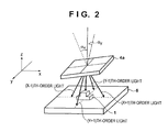
- the diffracted light beams of the plurality of orders generated by the diffraction grating 4a propagate in directions different from each other and irradiate the object 1 on the stage with angles (convergence angles), as shown in Fig. 2 .
- the diffracted light beams simultaneously irradiate the object 1 are projected onto the object in a superimposed manner.
- the diffraction grating 4a may be arranged to be tilted with respect to the optical axis of the optical system 3 such that the pattern light is obliquely incident on the diffraction grating 4a. This is because the plurality of diffracted light beams generated by the diffraction grating 4a can irradiate the object 1 with convergence angles different from each other.
- a two-dimensional diffraction grating in which a conspicuous change in the diffraction efficiency caused by polarization is little, that is, the diffraction direction is not changed by the polarization state of incident light is used as the diffraction grating 4a.
- the present invention is not limited to this.
- a one-dimensional diffraction grating may be used as the diffraction grating 4a.
- the measuring apparatus 10 having the above-described arrangement when determining the shape of the object 1 based on the image of the object 1 captured by the image sensing unit 5, the phase of each of the plurality of diffracted light beams incident on the image sensing unit 5 needs to be obtained.
- the measuring apparatus 10 according to the first embodiment includes a change unit that changes the distance between the object 1 and the diffraction grating 4a (relative positions of the object 1 and the diffraction grating 4a).
- the processing unit 7 of the measuring apparatus 10 repeats a step of causing the change unit to change the distance between the object 1 and the diffraction grating 4a so as to shift the phase of each diffracted light beam incident on the image sensing unit 5 and causing the image sensing unit 5 to capture the object 1, thereby obtaining a plurality of images of the object 1.
- Each image obtained by the image sensing unit 5 at this time represents the intensity distribution of light of the plurality of superimposed diffracted light beams.
- the processing unit 7 performs discrete Fourier transform (to be referred to as DFT hereinafter) for the plurality of images each representing the light intensity distribution, thereby obtaining the phase distribution of each diffracted light beam on the imaging plane of the image sensing unit 5 and determining the shape of the object 1.
- DFT discrete Fourier transform
- an actuator 8 that drives the diffraction grating 4a in a direction (Z direction) parallel to the optical axis of the optical system 3 is used as the change unit, and the diffraction grating 4a is driven in the Z direction, thereby changing the distance between the object 1 and the diffraction grating 4a.
- the present invention is not limited to this.
- the stage 6 movable in the Z direction may be used as the change unit, and the object 1 may be driven in the Z direction by the stage 6, thereby changing the distance between the object 1 and the diffraction grating 4a. The distance may be changed relatively by both the actuator 8 and the stage 6.
- Fig. 3 is a flowchart showing the method of obtaining the phase distribution of each diffracted light beam on the imaging plane of the image sensing unit 5.
- the processing unit 7 irradiates the object 1 with a plurality of diffracted light beams (pattern light beams) generated by the diffraction grating 4a arranged to be tilted by an angle ⁇ x in the X direction and an angle ⁇ y in the Y direction with respect to the optical axis of the optical system 3, as shown in Fig. 2 .
- a pattern on the grating in which sinusoidal patterns are superimposed while being crossed can be used as the pattern light.
- the processing unit 7 causes the image sensing unit 5 to capture the object 1 irradiated with the plurality of diffracted light beams.
- the processing unit 7 causes the change unit (actuator 8) to change the distance between the object 1 and the deflection unit 4 (diffraction grating 4a).
- step S104 the processing unit 7 determines whether the number of images captured by the image sensing unit 5 has reached the number (to be referred to as a predetermined number hereinafter) of images with which the phases of the diffracted light beams can be obtained. If the number of images captured by the image sensing unit 5 has not reached the predetermined number, the process returns to step S102 to cause the image sensing unit 5 to capture the object 1 in the state in which the distance between the object 1 and the diffraction grating 4a has been changed by the change unit in step S103.
- step S105 the processing unit 7 obtains the phase distribution of each diffracted light beam on the imaging plane of the image sensing unit 5 based on the plurality of images captured by the image sensing unit 5.
- the object 1 is irradiated with the plurality of diffracted light beams generated by the diffraction grating 4a in a superimposed manner.
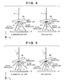
- there exist illumination light paths of diffracted light beams (the light paths of light beams that irradiate the object 1) and test light paths (the light paths of light beams reflected by the object 1) as many as the number of diffracted light beams, as shown in Figs. 4 and 5.
- Fig. 4 shows the diffracted light of each order in the X direction
- Fig. 5 shows the diffracted light of each order in the Y direction.
- each of Figs. 4 and 5 shows the illumination light paths
- the right view shows the test light paths.
- a total of 2-(2-K + 1) 2 diffracted light beams including the plurality of diffracted light beams in the X direction and the plurality of diffracted light beams in the Y direction irradiate the object 1 in the superimposed manner.
- A is the bias component of the pattern light that irradiates the object 1
- B is the intensity modulation component of the pattern light
- T x is the X-direction period of the pattern in the pattern light
- Ty is the Y-direction period of the pattern in the
- Fx is a phase change amount generated in each diffracted light beam when diffracted in the X direction
- Fy is a phase change amount generated in each diffracted light beam when diffracted in the Y direction.
- ⁇ x(x, y) and ⁇ y(x, y) are the phases (to be referred to as initial phases hereinafter) of the diffracted light incident on each pixel of the image sensing unit 5 before the change unit changes the distance between the object 1 and the diffraction grating 4a.
- ⁇ x k be the deflection angle of diffracted light diffracted in the X direction, as shown in Fig. 4
- ⁇ y k be the deflection angle of diffracted light diffracted in the Y direction, as shown in Fig. 5 .
- phase change amounts Fx and Fy are given by
- F ⁇ x b a sin ⁇ ⁇ x a - cos ⁇ x a tan ⁇ x b
- F ⁇ x b a sin ⁇ ⁇ y a - cos ⁇ y a tan ⁇ y b
- k is the diffraction order to which the diffraction order a of the illumination light path or the diffraction order b of the test light path is input.
- the intensity of light detected in each pixel of the image sensing unit 5 is the synthesis of intensities of the diffracted light beams generated by the diffraction grating 4a.
- the phase of each diffracted light beam can selectively be calculated by meeting a condition to be described later.
- the orders a and b can arbitrarily be combined.
- the diffraction grating 4a is moved in the Z direction by the moving amount ⁇ Z meeting the conditions of expressions (15), the phase of each diffracted light beam can accurately be obtained without causing crosstalk from each diffracted light beam.
- a wavelength ⁇ of the light source 2a is 800 nm
- a diffraction grating constant D x of the diffraction grating 4a in the X direction is 602 lines/mm
- a diffraction grating constant Dy of the diffraction grating 4a in the Y direction is 614 lines/mm considering Oth-order to ⁇ 1st-order diffracted light beams.
- an angle ⁇ x is 27.10°
- an angle ⁇ y is 27.45°
- a period is 0.95 mm
- a period Ty is 0.95 mm
- the moving amount ⁇ Z of the diffraction grating 4a is -0.43 mm.
- the phase shift amounts of the diffracted light beams in the X and Y directions can have values shown in Table 1 below.
- the predetermined number can be determined as "122".
- X direction ⁇ ⁇ ⁇ x 0 + 1 43 ⁇ ⁇ / 97
- ⁇ ⁇ ⁇ x 0 - 1 - 37 ⁇ ⁇ / 58
- ⁇ ⁇ ⁇ x + 1 0 - 29 ⁇ ⁇ / 57
- ⁇ ⁇ ⁇ x + 1 - 1 - ⁇
- ⁇ ⁇ x - 1 + 1 109 ⁇ ⁇ / 83
- ⁇ ⁇ ⁇ x - 1 0 46 ⁇ ⁇ / 51
- the measuring apparatus 10 includes, in the deflection unit 4, the diffraction grating 4a that diffracts pattern light emitted from the optical system 3 and generates diffracted light of a plurality of orders.
- the measuring apparatus 10 repeats the step of causing the change unit to change the distance between the object 1 and the diffraction grating 4a and causing the image sensing unit 5 to capture the object 1, thereby obtaining a plurality of images and obtaining the phases of each diffracted light beam based on the plurality of images.
- the measuring apparatus 10 according to the first embodiment can perform measurement with fewer blind spots or measurement in a wider measurement range using a synthetic wavelength.
- the measuring apparatus according to the second embodiment has the same apparatus arrangement as the measuring apparatus 10 according to the first embodiment, and a description thereof will be omitted here.
- the measuring apparatus according to the second embodiment not only causes a change unit (actuator 8) to change the distance between a diffraction grating 4a and an object 1 to be measured but also causes a conversion element 2c of an emitting unit 2 to change the period of the arrangement of bright and dark portions in pattern light.
- the measuring apparatus according to the second embodiment thus shifts the phase of each diffracted light beam incident on an image sensing unit 5.
- Fig. 6 is a flowchart showing the method of obtaining the phase distribution of each diffracted light beam on the imaging plane of the image sensing unit 5.
- the processing unit 7 irradiates the object with a plurality of diffracted light beams (pattern light beams) generated by the diffraction grating 4a arranged to be tilted by an angle ⁇ x in the X direction and an angle ⁇ y in the Y direction with respect to the optical axis of an optical system 3, as shown in Fig. 2 .
- step S202 the processing unit 7 causes the image sensing unit 5 to capture the object 1 irradiated with the plurality of diffracted light beams.
- step S203 the processing unit 7 causes the change unit to change the distance between the object 1 and a deflection unit 4 (diffraction grating 4a), and additionally, causes the conversion element 2c of the emitting unit 2 to change the period of the arrangement of bright and dark portions in pattern light.
- the conversion element 2c includes a mask with a pattern on which optically transparent portions and light-shielding portions are periodically arranged
- the processing unit 7 controls the conversion element 2c so that the mask moves in the Y direction or Z direction.
- the processing unit 7 controls the conversion element 2c so as to individually drive a plurality of elements of the liquid crystal element or the DMD. This can shift the phases of the diffracted light beams incident on the image sensing unit 5 by phase shift amounts different from each other.
- step S204 the processing unit 7 determines whether the number of images captured by the image sensing unit 5 has reached a predetermined number. If the number of images captured by the image sensing unit 5 has not reached the predetermined number, the process returns to step S202 to cause the image sensing unit 5 to capture the object 1. On the other hand, if the number of images captured by the image sensing unit 5 has reached the predetermined number, the process advances to step S205. In step S205, the processing unit 7 obtains the phase distribution of each diffracted light beam on the imaging plane of the image sensing unit 5 based on the plurality of images captured by the image sensing unit 5.
- the intensity I(x, y) of light detected in each pixel of the image sensing unit 5 when the diffraction grating 4a is moved by the change unit by ⁇ Z in the Z direction is given by equation (4), as in the first embodiment.
- ⁇ x be the change amount of the period of pattern light in the X direction by the conversion element 2c
- ⁇ y be the change amount of the period of pattern light in the Y direction
- the processing unit repeats the step of moving the diffraction grating 4a by the moving amount ⁇ Z so that equations (21) meet the conditions of equations (14) and (15) and changing the period of the pattern light by the change amounts ⁇ x and ⁇ y and causing the image sensing unit 5 to capture the object 1.
- the processing unit 7 can thus accurately obtain the phases of each diffracted light beam without causing crosstalk from each diffracted light beam.
- a wavelength ⁇ of the light source 2a is 800 nm
- a diffraction grating constant D x of the diffraction grating 4a in the X direction is 625 lines/mm
- a diffraction grating constant Dy of the diffraction grating 4a in the Y direction is 642 lines/mm considering Oth-order to ⁇ 1st-order diffracted light beams.
- an angle ⁇ x is 19.52°
- an angle ⁇ y is 19.41°
- a period is 0.95 mm
- a period Ty is 0.97 mm
- the moving amount ⁇ Z of the diffraction grating 4a is -0.43 mm.
- the change amount ⁇ x of the period of the pattern light in the X direction is -0.056 rad
- the change amount ⁇ y of the period of the pattern light in the Y direction is - 0.043 rad.
- the phase shift amounts of the diffracted light beams in the X direction and the phase shift amounts of the diffracted light beams in the Y direction can have values shown in Table 2 below. From equations (14) and (15), the predetermined number can be determined as "145".
- the measuring apparatus repeats the step of moving the diffraction grating 4a and changing the period of pattern light, and causing the image sensing unit 5 to capture the object 1, thereby obtaining a plurality of images and obtaining the phases of each diffracted light beam based on the plurality of images.
- the measuring apparatus according to the second embodiment can thus perform measurement with fewer blind spots or measurement in a wider measurement range using a synthetic wavelength, like the measuring apparatus 10 according to the first embodiment.
- the measuring apparatus changes the phases of each diffracted light beam by moving the diffraction grating 4a in the Z direction and changing the period of pattern light.
- the present invention is not limited to this.
- the phases of each diffracted light beam may be changed by moving the diffraction grating 4a in the Z direction and additionally changing the tilt of the diffraction grating 4a so as to change the incident angle of the pattern light with respect to the diffraction grating 4a.
- the measuring apparatus includes, for example, a second change unit that changes the tilt of the diffraction grating 4a, and the tilt of the diffraction grating 4a can be changed by the second change unit.
- the second change unit according to the second embodiment can be included in, for example, the change unit.
- the phases of each diffracted light beam may be also changed simultaneously using moving the diffraction grating 4a in the Z direction, changing the period of pattern light, and changing the angle of the diffraction grating 4a.
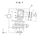
- FIG. 7 is a schematic view showing the measuring apparatus 30 according to the third embodiment.
- the measuring apparatus 30 according to the third embodiment provides a deflection unit 4 with a polarization diffraction grating 4b whose diffraction efficiency (deflection direction) conspicuously changes depending on the polarization state of incident light and a waveplate 4c.
- an optical system 3 is arranged to be tilted so that the deflection direction of the polarization diffraction grating 4b becomes parallel to the Z direction, and the polarization diffraction grating 4b and the waveplate 4c are arranged such that pattern light emitted from the optical system 3 is vertically incident on them.
- a light source 2a of an emitting unit 2 is configured to emit light (linearly polarized light) having only deflection components in a certain direction.
- the pattern light incident on the deflection unit 4 (waveplate 4c) thus has the polarization state of linearly polarized light.
- the measuring apparatus 30 according to the third embodiment can increase the phase difference between the diffracted light of a plurality of orders by controlling the polarization state of the pattern light using the waveplate 4c and thus making the light path of illumination light different from that of test light.
- the arrangement of each component of the measuring apparatus 30 according to the third embodiment is the same as in the measuring apparatus 10 according to the first embodiment, and a description thereof will be omitted.
- the measuring apparatus 30 can obtain the phase distribution of each diffracted light beam on the imaging plane of the image sensing unit 5 by performing the steps of the flowchart shown in Fig. 3 .
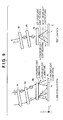
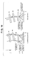
- the processing unit 7 irradiates an object 1 to be measured with a plurality of diffracted light beams (pattern light beams) generated by a diffraction grating 4a of the deflection unit 4, as shown in Figs. 8 to 10 .
- Fig. 8 is a schematic view showing the arrangement of the constituent elements of the deflection unit 4.
- Fig. 9 is a schematic view showing the arrangement of the constituent elements of the deflection unit 4 in the X direction.
- Fig. 8 is a schematic view showing the arrangement of the constituent elements of the deflection unit 4.
- FIG. 10 is a schematic view showing the arrangement of the constituent elements of the deflection unit 4 in the Y direction.
- the left view of each of Figs. 9 and 10 shows the illumination light paths, and the right view shows the test light paths.
- the polarization state of pattern light incident on the deflection unit 4 is set to linearly polarized light
- the pattern light is converted into circularly polarized light by the waveplate 4c, deflected by the polarization diffraction grating 4b, and is incident on the diffraction grating 4a with an angle.
- the angle (incident angle) of the pattern light that is emitted from the polarization diffraction grating 4b and is incident on the diffraction grating 4a is set to an angle ⁇ x in the X direction and an angle ⁇ y in the Y direction.
- Steps S102 to S105 are the same as the steps of the measuring apparatus 10 according to the first embodiment, and a description thereof will be omitted here.
- An intensity I(x, y) of light detected in each pixel of the image sensing unit 5 is given by equation (3), as in the first embodiment.
- ⁇ x k be the deflection angle of diffracted light deflected by the diffraction grating 4a
- ⁇ x k be the light-receiving angle at which the diffracted light reflected by the object 1 is received by the diffraction grating 4a in the X direction.
- ⁇ y k be the deflection angle of diffracted light deflected by the diffraction grating
- ⁇ y k be the light-receiving angle at which the diffracted light reflected by the object is received by the diffraction grating in the Y direction.
- F ⁇ y b a sin ⁇ y a - cos ⁇ y a tan ⁇ y b
- the processing unit 7 repeats the step of moving the diffraction grating 4a by the moving amount ⁇ Z so that equations (26) meet the conditions of equations (14) and (15) and causing the image sensing unit 5 to capture the object 1, as in the first embodiment.
- the processing unit 7 can thus accurately obtain the phases of each diffracted light beam without causing crosstalk from each diffracted light beam.
- a wavelength ⁇ of the light source 2a is 800 nm
- a diffraction grating constant D x of the diffraction grating 4a in the X direction is 572 lines/mm
- a diffraction grating constant Dy of the diffraction grating 4a in the Y direction is 572 lines/mm considering 0th-order to ⁇ 1st-order diffracted light beams.
- an angle ⁇ x is 27.20°
- an angle ⁇ y is 27.20°
- a period is 0.1 mm
- a period Ty is 0.05 mm
- the moving amount ⁇ Z of the diffraction grating 4a is -0.017 mm.
- the phase shift amounts of the diffracted light beams in the X and Y directions can have values shown in Table 3 below.
- the predetermined number can be determined as "100".
- the deflection unit 4 is provided with the polarization diffraction grating 4b whose deflection direction changes depending on the polarization state and the waveplate 4c.
- the optical system 3 is arranged to be tilted so that the deflection direction of the polarization diffraction grating 4b becomes parallel to the Z direction.
- the measuring apparatus 30 according to the third embodiment repeats the step of moving the diffraction grating 4a and causing the image sensing unit 5 to capture the object 1, thereby obtaining a plurality of images and obtaining the phases of each diffracted light beam based on the plurality of images.
- the measuring apparatus 30 according to the third embodiment can thus perform measurement with fewer blind spots or measurement in a wider measurement range using a synthetic wavelength, like the measuring apparatus 10 according to the first embodiment.
- the measuring apparatus according to the fourth embodiment has the same apparatus arrangement as the measuring apparatus 30 according to the third embodiment, and a description thereof will be omitted here.
- the measuring apparatus according to the fourth embodiment not only causes a change unit to change the distance between a diffraction grating 4a and an object 1 to be measured but also causes a conversion element 2c of an emitting unit 2 to change the period of the arrangement of bright and dark portions in pattern light, thereby shifting the phase of each diffracted light beam incident on an image sensing unit 5.
- the measuring apparatus according to the fourth embodiment can obtain the phase distribution of each diffracted light beam on the imaging plane of the image sensing unit 5 by performing the steps of the flowchart shown in Fig. 6 , like the measuring apparatus according to the second embodiment.
- the steps (steps S201 to S205) of the flowchart of Fig. 6 are the same as in the second embodiment, and a description thereof will be omitted here.
- ⁇ x be the change amount of the period of pattern light in the X direction by the conversion element 2c and ⁇ y be the change amount of the period of pattern light in the Y direction.
- the processing unit 7 repeats the step of moving the diffraction grating 4a by the moving amount ⁇ Z so that equations (29) meet the conditions of equations (14) and (15) and changing the period of the pattern light by the change amounts ⁇ x and ⁇ y and causing the image sensing unit 5 to capture the object 1.
- the processing unit 7 can thus accurately obtain the phases of each diffracted light beam without causing crosstalk from each diffracted light beam.
- a wavelength ⁇ of a light source 2a is 800 nm
- a diffraction grating constant D x of the diffraction grating 4a in the X direction is 572 lines/mm
- a diffraction grating constant Dy of the diffraction grating 4a in the Y direction is 572 lines/mm considering 0th-order to ⁇ 1st-order diffracted light beams.
- an angle ⁇ x is 27.20°
- an angle ⁇ y is 27.20°
- a period is 0.1 mm
- a period Ty is 0.1 mm
- the moving amount ⁇ Z of the diffraction grating 4a is 0.034 mm.
- the phase shift amounts of the diffracted light beams in the X and Y directions can have values shown in Table 4 below. From equations (14) and (15), the predetermined number can be determined as "50".
- the deflection unit 4 is provided with the polarization diffraction grating 4b whose deflection direction changes depending on the polarization state and the waveplate 4c.
- the optical system 3 is arranged to be tilted so that the deflection direction of the polarization diffraction grating 4b becomes parallel to the Z direction.
- the measuring apparatus according to the fourth embodiment repeats the step of moving the diffraction grating 4a and changing the period of pattern light, and causing the image sensing unit 5 to capture the object 1, thereby obtaining a plurality of images and obtaining the phases of each diffracted light beam based on the plurality of images.
- the measuring apparatus according to the fourth embodiment can thus perform measurement with fewer blind spots or measurement in a wider measurement range using a synthetic wavelength.
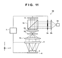
- a measuring apparatus 50 according to the fifth embodiment of the present invention will be described with reference to Fig. 11 .
- the measuring apparatus 50 according to the fifth embodiment is different from the measuring apparatus 10 according to the first embodiment in the arrangement of a deflection unit 4.
- the deflection unit 4 can include a liquid crystal element 4d capable of changing the polarization state of pattern light emitted from an optical system 3, and a polarization diffraction grating 4e whose diffraction efficiency (deflection direction) conspicuously changes depending on the polarization state of the pattern light emitted from the liquid crystal element 4d.
- the measuring apparatus 50 causes a processing unit 7 to control the liquid crystal element 4d such that the pattern light is deflected inward from outside of the polarization diffraction grating 4e and irradiates an object 1 to be measured.
- the measuring apparatus 50 can thus limit the region where the pattern light irradiates the object 1 and also reduce generation of signals unnecessary for measurement.
- Fig. 11 is a schematic view showing the measuring apparatus 50 according to the fifth embodiment.
- the measuring apparatus 50 according to the fifth embodiment can include an emitting unit 2, the optical system 3, the deflection unit 4, an image sensing unit 5, a stage 6, and the processing unit 7.
- a light source 2a of the emitting unit 2 emits light (linearly polarized light) having only deflection components in a certain direction.
- the light emitted from the light source 2a is collimated by a collimator lens 2b and is then incident on a conversion element 2c so as to be converted into pattern light having a periodical arrangement of bright and dark portions.
- the conversion element 2c can use, for example, a mask with a pattern on which optically transparent portions and light-shielding portions are periodically (alternately) arranged, a liquid crystal element, or a digital mirror device.
- the central portion of the conversion element 2c shields light so that the pattern light is incident on only the peripheral portion of the deflection unit 4.
- the pattern light emitted from the emitting unit 2 is reflected by a polarizing beam splitter 3a in the optical system 3 and passed through two objective lenses 3b and 3c so as to be emitted from the optical system 3 with a larger diameter and incident on the deflection unit 4.
- Fig. 12 is a schematic view showing the measuring apparatus 50 according to the fifth embodiment in which the arrangement of the deflection unit 4 is illustrated.
- the deflection unit 4 includes the liquid crystal element 4d capable of changing the polarization state of pattern light emitted from the optical system 3, and the polarization diffraction grating 4e whose diffraction efficiency conspicuously changes depending on the polarization state of the pattern light emitted from the liquid crystal element 4d.
- two liquid crystal elements 4d 1 and 4d 2 and two polarization diffraction gratings 4e 1 and 4e 2 are alternately arranged along the Z direction.
- the polarization diffraction grating 4e can deflect pattern light in a direction that changes between a case where left-handed circularly polarized pattern light is incident (left view) and a case where right-handed circularly polarized pattern light is incident (right view).
- pattern light (linearly polarized light in the X direction) incident on the left end of the first liquid crystal element 4d 1 undergoes polarization state control by the liquid crystal element 4d 1 and is emitted as left-handed circularly polarized light.
- the pattern light that has changed to the left-handed circularly polarized light is incident on the peripheral portion (left end) of the first polarization diffraction grating 4e 1 .
- the pattern light incident on the polarization diffraction grating 4e 1 is left-handed circularly polarized light and is therefore deflected in the +X direction in Fig. 12 and also converted into right-handed circularly polarized light.
- the pattern light deflected by the polarization diffraction grating 4e 1 is incident on the left end of the second liquid crystal element 4d 2 . After having undergone polarization state control, the pattern light is emitted from the liquid crystal element 4d 2 as left-handed circularly polarized light. The pattern light that has changed to the left-handed circularly polarized light is incident on the peripheral portion (left end) of the second polarization diffraction grating 4e 2 . The pattern light is deflected in the +X direction in Fig. 12 by the polarization diffraction grating 4e 2 and irradiates the left region of the object 1.
- pattern light (linearly polarized light) incident on the right end of the first liquid crystal element 4d 1 undergoes polarization state control by the liquid crystal element 4d 1 and is emitted as right-handed circularly polarized light.
- the pattern light that has changed to the right-handed circularly polarized light is incident on the peripheral portion (right end) of the first polarization diffraction grating 4e 1 .
- the pattern light is deflected in the -X direction in Fig. 12 and also converted into left-handed circularly polarized light by the polarization diffraction grating 4e 1 .
- the pattern light deflected by the polarization diffraction grating 4e 1 is incident on the right end of the second liquid crystal element 4d 2 . After having undergone polarization state control, the pattern light is emitted from the liquid crystal element 4d 2 as right-handed circularly polarized light. The pattern light that has changed to the right-handed circularly polarized light is incident on the peripheral portion (right end) of the second polarization diffraction grating 4e 2 . The pattern light is deflected in the -X direction in Fig. 12 by the polarization diffraction grating 4e 2 and irradiates the right region of the object 1.
- the pattern light reflected by the left region of the object 1 is partially vertically incident on the left side of the central portion of the polarization diffraction grating 4e 2 .
- the pattern light incident on the polarization diffraction grating 4e 2 is right-handed circularly polarized light and is therefore deflected in the +X direction in Fig. 12 and also converted into left-handed circularly polarized light by the polarization diffraction grating 4e 2 .
- the pattern light that has changed to the left-handed circularly polarized light is incident on the liquid crystal element 4d 2 , undergoes polarization state control, and is incident on the polarization diffraction grating 4e 1 as right-handed circularly polarized light.
- the pattern light incident on the polarization diffraction grating 4e 1 is deflected in the +X direction in Fig. 12 and also converted into left-handed circularly polarized light by the polarization diffraction grating 4e 1 , and is incident on the liquid crystal element 4d 1 .
- the pattern light incident on the liquid crystal element 4d 1 undergoes polarization state control and is vertically emitted from the liquid crystal element 4d 1 as linearly polarized light in the Y direction.
- the pattern light reflected by the right region of the object 1 is partially vertically incident on the right side of the central portion of the polarization diffraction grating 4e 2 .
- the pattern light incident on the polarization diffraction grating 4e 2 is left-handed circularly polarized light and is therefore deflected in the -X direction in Fig. 12 and also converted into right-handed circularly polarized light by the polarization diffraction grating 4e 2 .
- the pattern light that has changed to the right-handed circularly polarized light is incident on the liquid crystal element 4d 2 , undergoes polarization state control, and is incident on the polarization diffraction grating 4e 1 as left-handed circularly polarized light.
- the pattern light incident on the polarization diffraction grating 4e 1 is deflected in the -X direction in Fig. 12 and also converted into right-handed circularly polarized light by the polarization diffraction grating 4e 1 , and is incident on the liquid crystal element 4d 1 .
- the pattern light incident on the liquid crystal element 4d 1 undergoes polarization state control and is vertically emitted from the liquid crystal element 4d 1 as linearly polarized light in the Y direction.
- the pattern light vertically emitted from the liquid crystal element 4d 1 is converged by the objective lens 3c, passes through an aperture stop 3d, and is incident on the polarizing beam splitter 3a.
- the pattern light incident on the polarizing beam splitter 3a is linearly polarized light in the Y direction, and therefore passes through the polarizing beam splitter 3a and is incident on the image sensing unit 5.
- pattern light that is reflected by the object 1 and is vertically incident on the deflection unit 4 (polarization diffraction grating 4e 2 ) is vertically emitted from the deflection unit 4 (liquid crystal element 4d 1 ) and can therefore pass through the aperture stop 3d.
- the measuring apparatus 50 according to the fifth embodiment can make only pattern light reflected with a predetermined convergence angle with respect to the pattern light that irradiates the object 1 be incident on the image sensing unit 5 and reduce generation of signals unnecessary for measurement in the image sensing unit 5.
- the measuring apparatus 50 according to the fifth embodiment may repeat the step of changing the distance between the deflection unit 4 and the object 1 or changing the period of the pattern light and causing the image sensing unit 5 to capture the object 1, thereby obtaining a plurality of images.
- the measuring apparatus 50 according to the fifth embodiment can change the region of the object 1 irradiated with pattern light as shown in Fig. 14 , by controlling the conversion element 2c of the emitting unit 2 or the liquid crystal element 4d of the deflection unit 4.
- a method of manufacturing an article according to an embodiment of the present invention is used to, for example, manufacture an article such as a metal part or optical element.
- the method of manufacturing an article according to the embodiment includes a step of measuring the shape of an object using the above-described measuring apparatus, and a step of processing the object based on the measuring result in the preceding step. For example, the shape of an object is measured using the measuring apparatus, and the object is processed (manufactured) based on the measuring result so that the shape of the object matches the design value.
- the method of manufacturing an article according to the embodiment can measure the shape of an object by the measuring apparatus at high accuracy, and thus is superior to a conventional method in at least one of the performance, quality, productivity, and production cost of the article.
Landscapes
- Physics & Mathematics (AREA)
- General Physics & Mathematics (AREA)
- Optics & Photonics (AREA)
- Engineering & Computer Science (AREA)
- Computer Vision & Pattern Recognition (AREA)
- Nonlinear Science (AREA)
- Chemical & Material Sciences (AREA)
- Crystallography & Structural Chemistry (AREA)
- Length Measuring Devices By Optical Means (AREA)
- Measurement Of Optical Distance (AREA)
Applications Claiming Priority (1)
| Application Number | Priority Date | Filing Date | Title |
|---|---|---|---|
| JP2014050532A JP6417099B2 (ja) | 2014-03-13 | 2014-03-13 | 計測装置、および物品の製造方法 |
Publications (2)
| Publication Number | Publication Date |
|---|---|
| EP2918968A2 true EP2918968A2 (de) | 2015-09-16 |
| EP2918968A3 EP2918968A3 (de) | 2015-12-23 |
Family
ID=52577602
Family Applications (1)
| Application Number | Title | Priority Date | Filing Date |
|---|---|---|---|
| EP15000519.7A Withdrawn EP2918968A3 (de) | 2014-03-13 | 2015-02-23 | Messvorrichtung und verfahren zur herstellung eines artikels |
Country Status (3)
| Country | Link |
|---|---|
| US (1) | US9797717B2 (de) |
| EP (1) | EP2918968A3 (de) |
| JP (1) | JP6417099B2 (de) |
Cited By (3)
| Publication number | Priority date | Publication date | Assignee | Title |
|---|---|---|---|---|
| EP3438741A1 (de) * | 2017-07-31 | 2019-02-06 | Samsung Electronics Co., Ltd. | Projektor mit einer nanostruktur im sub-wellenlängenbereich zur erzeugung strukturierten lichts |
| CN111238396A (zh) * | 2020-02-10 | 2020-06-05 | 北京理工大学 | 一种瞬态数字莫尔移相干涉测量装置和方法 |
| US10922828B2 (en) | 2017-07-31 | 2021-02-16 | Samsung Electronics Co., Ltd. | Meta projector and electronic apparatus including the same |
Families Citing this family (8)
| Publication number | Priority date | Publication date | Assignee | Title |
|---|---|---|---|---|
| JP6440836B2 (ja) * | 2015-06-10 | 2018-12-19 | 株式会社Pfu | 画像処理システム、画像読取装置、領域検出方法及びコンピュータプログラム |
| JP6578436B2 (ja) * | 2015-10-08 | 2019-09-18 | エーエスエムエル ネザーランズ ビー.ブイ. | トポグラフィ測定システム |
| JP2019015527A (ja) * | 2017-07-04 | 2019-01-31 | 株式会社ミツトヨ | 画像測定装置及びプログラム |
| US10802382B2 (en) | 2018-07-24 | 2020-10-13 | Qualcomm Incorporated | Adjustable light projector for flood illumination and active depth sensing |
| EP3640629B1 (de) * | 2018-10-15 | 2024-05-08 | Koh Young Technology Inc | Vorrichtung und verfahren zur fokuslosen inspektion |
| US11022813B2 (en) | 2019-04-08 | 2021-06-01 | Qualcomm Incorporated | Multifunction light projector with multistage adjustable diffractive optical elements |
| US11521504B2 (en) * | 2020-03-18 | 2022-12-06 | Rosemount Aerospace Inc. | Method and system for aircraft taxi strike alerting |
| KR20250159175A (ko) | 2023-03-15 | 2025-11-10 | 엘엠아이 테크놀로지스 인코포레이티드 | 광학 측정 시스템 |
Citations (1)
| Publication number | Priority date | Publication date | Assignee | Title |
|---|---|---|---|---|
| JP2013178174A (ja) | 2012-02-28 | 2013-09-09 | Motoharu Fujigaki | 複数の格子を用いた三次元形状計測装置 |
Family Cites Families (14)
| Publication number | Priority date | Publication date | Assignee | Title |
|---|---|---|---|---|
| JPS63148106A (ja) * | 1986-12-10 | 1988-06-21 | Minolta Camera Co Ltd | 物体位置測定装置 |
| CA2044820C (en) * | 1990-06-19 | 1998-05-26 | Tsugito Maruyama | Three-dimensional measuring apparatus |
| EP1084430B1 (de) * | 1998-05-01 | 2006-07-26 | Metrologic Instruments, Inc. | Doe-basierte systeme (streuende optische elemente) und vorrichtungen zur herstellung von laserstrahlen veränderter strahlcharakteristik |
| EP1875162B1 (de) * | 2005-04-06 | 2014-06-11 | Dimensional Photonics International, Inc. | Definition eines positionsfehlers einer optischen komponente mittels strukturierter lichtmuster |
| US7492450B2 (en) | 2005-10-24 | 2009-02-17 | General Electric Company | Methods and apparatus for inspecting an object |
| JP2007155379A (ja) * | 2005-12-01 | 2007-06-21 | Tokyo Univ Of Agriculture & Technology | 三次元形状計測装置および三次元形状計測方法 |
| US8542421B2 (en) * | 2006-11-17 | 2013-09-24 | Celloptic, Inc. | System, apparatus and method for extracting three-dimensional information of an object from received electromagnetic radiation |
| US8224066B2 (en) * | 2007-05-29 | 2012-07-17 | Gerd Haeusler | Method and microscopy device for the deflectometric detection of local gradients and the three-dimensional shape of an object |
| JP5170154B2 (ja) * | 2010-04-26 | 2013-03-27 | オムロン株式会社 | 形状計測装置およびキャリブレーション方法 |
| JP2012093235A (ja) * | 2010-10-27 | 2012-05-17 | Nikon Corp | 三次元形状測定装置、三次元形状測定方法、構造物の製造方法および構造物製造システム |
| JP2013113581A (ja) * | 2011-11-24 | 2013-06-10 | Suwa Optronics:Kk | 3次元形状データ取得装置の光学測定ヘッド |
| JP6043528B2 (ja) * | 2012-07-20 | 2016-12-14 | 株式会社日立ハイテクノロジーズ | パターン測定装置 |
| JP6273127B2 (ja) * | 2013-11-14 | 2018-01-31 | キヤノン株式会社 | 計測装置、および物品の製造方法 |
| US9631973B2 (en) * | 2013-12-13 | 2017-04-25 | Raytheon Company | Multifunction imager |
-
2014
- 2014-03-13 JP JP2014050532A patent/JP6417099B2/ja active Active
-
2015
- 2015-02-23 EP EP15000519.7A patent/EP2918968A3/de not_active Withdrawn
- 2015-03-10 US US14/643,170 patent/US9797717B2/en not_active Expired - Fee Related
Patent Citations (1)
| Publication number | Priority date | Publication date | Assignee | Title |
|---|---|---|---|---|
| JP2013178174A (ja) | 2012-02-28 | 2013-09-09 | Motoharu Fujigaki | 複数の格子を用いた三次元形状計測装置 |
Cited By (6)
| Publication number | Priority date | Publication date | Assignee | Title |
|---|---|---|---|---|
| EP3438741A1 (de) * | 2017-07-31 | 2019-02-06 | Samsung Electronics Co., Ltd. | Projektor mit einer nanostruktur im sub-wellenlängenbereich zur erzeugung strukturierten lichts |
| US10922828B2 (en) | 2017-07-31 | 2021-02-16 | Samsung Electronics Co., Ltd. | Meta projector and electronic apparatus including the same |
| US11042243B2 (en) | 2017-07-31 | 2021-06-22 | Samsung Electronics Co., Ltd. | Meta projector and electronic apparatus including the same |
| US11449178B2 (en) | 2017-07-31 | 2022-09-20 | Samsung Electronics Co., Ltd. | Meta projector and electronic apparatus including the same |
| CN111238396A (zh) * | 2020-02-10 | 2020-06-05 | 北京理工大学 | 一种瞬态数字莫尔移相干涉测量装置和方法 |
| CN111238396B (zh) * | 2020-02-10 | 2021-03-09 | 北京理工大学 | 一种瞬态数字莫尔移相干涉测量装置和方法 |
Also Published As
| Publication number | Publication date |
|---|---|
| JP6417099B2 (ja) | 2018-10-31 |
| US20150260510A1 (en) | 2015-09-17 |
| EP2918968A3 (de) | 2015-12-23 |
| JP2015175642A (ja) | 2015-10-05 |
| US9797717B2 (en) | 2017-10-24 |
Similar Documents
| Publication | Publication Date | Title |
|---|---|---|
| EP2918968A2 (de) | Messvorrichtung und verfahren zur herstellung eines artikels | |
| KR102386664B1 (ko) | 분광 빔 프로파일 계측 | |
| TWI484139B (zh) | 彩色共焦掃描裝置 | |
| KR101790830B1 (ko) | 간섭계, 리소그래피 장치, 및 물품 제조 방법 | |
| JP5172040B2 (ja) | 表面形状測定方法及び表面形状測定装置 | |
| US20060285111A1 (en) | Apparatuses and methods for enhanced critical dimension scatterometry | |
| KR102340495B1 (ko) | 스펙트럼 분석을 사용하는 간섭측정식 인코더 | |
| KR20120044064A (ko) | 광학 측정 장치 | |
| TW201527712A (zh) | 光學位置測量裝置 | |
| JP5648961B2 (ja) | 分光特性測定装置及びその校正方法 | |
| KR20120137274A (ko) | 평면도 측정장치 및 평면도 측정방법 | |
| KR20190033421A (ko) | 위상차 측정 장치 및 위상차 측정 방법 | |
| JP6273127B2 (ja) | 計測装置、および物品の製造方法 | |
| US20230152083A1 (en) | Measuring device, exposure device, and measurement method | |
| KR20160052992A (ko) | 다기능 분광장치 | |
| CN114341602B (zh) | 分光测定装置 | |
| JP5675382B2 (ja) | シアリング干渉測定装置 | |
| US11686570B2 (en) | Displacement sensor and profile measurement apparatus | |
| KR102484108B1 (ko) | 2차원 각도 변위 측정 장치 | |
| WO2020255282A1 (ja) | 欠陥検査装置及び欠陥検査装置の較正方法 | |
| US10823550B2 (en) | Optical position measuring device | |
| JP2009145068A (ja) | 表面形状の測定方法および干渉計 | |
| JP6130805B2 (ja) | 距離測定装置および方法 | |
| US10801893B2 (en) | Spectroscope, wavelength measuring device, and spectrum measuring method | |
| JP2014169983A (ja) | 計測装置、計測方法、および物品の製造方法 |
Legal Events
| Date | Code | Title | Description |
|---|---|---|---|
| PUAI | Public reference made under article 153(3) epc to a published international application that has entered the european phase |
Free format text: ORIGINAL CODE: 0009012 |
|
| AK | Designated contracting states |
Kind code of ref document: A2 Designated state(s): AL AT BE BG CH CY CZ DE DK EE ES FI FR GB GR HR HU IE IS IT LI LT LU LV MC MK MT NL NO PL PT RO RS SE SI SK SM TR |
|
| AX | Request for extension of the european patent |
Extension state: BA ME |
|
| PUAL | Search report despatched |
Free format text: ORIGINAL CODE: 0009013 |
|
| AK | Designated contracting states |
Kind code of ref document: A3 Designated state(s): AL AT BE BG CH CY CZ DE DK EE ES FI FR GB GR HR HU IE IS IT LI LT LU LV MC MK MT NL NO PL PT RO RS SE SI SK SM TR |
|
| AX | Request for extension of the european patent |
Extension state: BA ME |
|
| RIC1 | Information provided on ipc code assigned before grant |
Ipc: G02B 27/42 20060101ALI20151117BHEP Ipc: G01B 11/25 20060101AFI20151117BHEP Ipc: G02B 5/30 20060101ALI20151117BHEP Ipc: G02B 26/08 20060101ALI20151117BHEP Ipc: G02B 27/09 20060101ALI20151117BHEP Ipc: G02F 1/13 20060101ALI20151117BHEP Ipc: G02B 27/28 20060101ALI20151117BHEP |
|
| RIN1 | Information on inventor provided before grant (corrected) |
Inventor name: NAKAJIMA, MASAKI |
|
| 17P | Request for examination filed |
Effective date: 20160623 |
|
| RBV | Designated contracting states (corrected) |
Designated state(s): AL AT BE BG CH CY CZ DE DK EE ES FI FR GB GR HR HU IE IS IT LI LT LU LV MC MK MT NL NO PL PT RO RS SE SI SK SM TR |
|
| 17Q | First examination report despatched |
Effective date: 20180813 |
|
| STAA | Information on the status of an ep patent application or granted ep patent |
Free format text: STATUS: THE APPLICATION HAS BEEN WITHDRAWN |
|
| 18W | Application withdrawn |
Effective date: 20190219 |