EP2919005A1 - Procédé et dispositif destinés à l'analyse d'azote (n) dans un échantillon - Google Patents
Procédé et dispositif destinés à l'analyse d'azote (n) dans un échantillon Download PDFInfo
- Publication number
- EP2919005A1 EP2919005A1 EP15000148.5A EP15000148A EP2919005A1 EP 2919005 A1 EP2919005 A1 EP 2919005A1 EP 15000148 A EP15000148 A EP 15000148A EP 2919005 A1 EP2919005 A1 EP 2919005A1
- Authority
- EP
- European Patent Office
- Prior art keywords
- nitrogen
- sample
- carrier gas
- detector
- molecular nitrogen
- Prior art date
- Legal status (The legal status is an assumption and is not a legal conclusion. Google has not performed a legal analysis and makes no representation as to the accuracy of the status listed.)
- Withdrawn
Links
Images

Classifications
-
- G—PHYSICS
- G01—MEASURING; TESTING
- G01N—INVESTIGATING OR ANALYSING MATERIALS BY DETERMINING THEIR CHEMICAL OR PHYSICAL PROPERTIES
- G01N31/00—Investigating or analysing non-biological materials by the use of the chemical methods specified in the subgroup; Apparatus specially adapted for such methods
- G01N31/12—Investigating or analysing non-biological materials by the use of the chemical methods specified in the subgroup; Apparatus specially adapted for such methods using combustion
-
- G—PHYSICS
- G01—MEASURING; TESTING
- G01N—INVESTIGATING OR ANALYSING MATERIALS BY DETERMINING THEIR CHEMICAL OR PHYSICAL PROPERTIES
- G01N33/00—Investigating or analysing materials by specific methods not covered by groups G01N1/00 - G01N31/00
- G01N33/0004—Gaseous mixtures, e.g. polluted air
- G01N33/0009—General constructional details of gas analysers, e.g. portable test equipment
- G01N33/0011—Sample conditioning
- G01N33/0019—Sample conditioning by preconcentration
-
- G—PHYSICS
- G01—MEASURING; TESTING
- G01N—INVESTIGATING OR ANALYSING MATERIALS BY DETERMINING THEIR CHEMICAL OR PHYSICAL PROPERTIES
- G01N1/00—Sampling; Preparing specimens for investigation
- G01N1/28—Preparing specimens for investigation including physical details of (bio-)chemical methods covered elsewhere, e.g. G01N33/50, C12Q
- G01N1/40—Concentrating samples
- G01N1/405—Concentrating samples by adsorption or absorption
Definitions
- the present invention relates to a method for the analysis of nitrogen (N) in a sample, wherein the sample is burned in an oxidation reactor with oxygen supply (O 2 ) and the resulting combustion gases are removed in a carrier gas flow (He) from the oxidation reactor, Subsequently, in this gas mixture existing nitrogen oxides (NO x ) are reduced to molecular nitrogen (N 2 ), then gaseous matrix components are separated from the gas mixture, so that the remaining carrier gas (He) and the molecular nitrogen contained therein (N 2 ) a detector for Determination of nitrogen (N 2 ) are supplied.
- O 2 oxygen supply
- He carrier gas flow
- the invention relates to a device for analyzing nitrogen (N) in a sample with an oxidation reactor receiving the sample during combustion, with an oxygen feed for feeding oxygen (O 2 ) into the oxidation reactor and with a carrier gas feed for supplying a carrier gas (He ) in the oxidation reactor, wherein, as seen in the flow direction of the carrier gas, the oxidation reactor is connected to a reduction tube, this reduction tube is connected to a separator for separating gaseous matrix components from the gas stream and the separation device with a detector for the determination of nitrogen (N 2 ) connected is.
- gaseous matrix constituents As far as the term gaseous matrix constituents is used above and in the following description, all constituents are included hereunder of the gas mixture present in the gas mixture in addition to the analyte, in the present process the total nitrogen TN (Total Nitrogen) being the analyte.
- Total Nitrogen Total Nitrogen
- the problem is that the low nitrogen concentrations, in particular in the field of stable isotopic analysis, can not or can not be analyzed with sufficient accuracy.
- the DE 35 38 778 A1 describes a method and apparatus for determining the level of nitrogen in a sample.
- the sample is burned under oxygen in a combustion tube (combustion zone) and the gaseous products formed, such as nitrogen and / or nitrogen oxides, are transferred to an analyzer in which they are quantitatively detected as nitrogen.
- the sample is burned in an oxygen-enriched, nitrogen-free, inert carrier gas and after combustion, in the flow direction of the carrier gas before the combustion zone, any condensation products deposited on the wall of the combustion tube are volatilized by heating and fed to the analysis device.
- the DE 197 08 179 A1 describes a reduction tube for nitrogen determination in the elemental analysis, wherein in the tube, a metal is filled in granulated form, which reduces nitrogen oxides to nitrogen and absorbs oxygen.
- a metal is filled in granulated form, which reduces nitrogen oxides to nitrogen and absorbs oxygen.
- metal tungsten and / or molybdenum is used, wherein the granulated material in the tube, as seen in the direction of the tube axis, is layered, each with an expansion buffer intermediate zone, such as quartz wool.
- the DE 20 25 390 A describes a method for the quantitative determination of the elements or isotopes contained in the individual chemical compounds of a substance mixture.
- the mixture of substances is separated by a gas chromatographic column in the individual compounds, and these are then subjected to a chemical reaction and detected.
- the reaction products formed in the chemical reaction are introduced while avoiding mixing in a second gas chromatographic column and eluted after completion of the separation of the original mixture of this material at elevated temperature and fed to the detectors.
- the present invention has for its object to provide a method and an apparatus which eliminate the disadvantages of the prior art described above or allow a lower limit of determination and a higher accuracy in the lower concentration range.
- An essential feature of the method according to the invention is the fact that the molecular nitrogen (N 2 ) contained in the carrier gas (He) is concentrated before being fed to the detector. This ensures that the analysis peaks become sharper, resulting in a higher peak at the same concentration and thus a better signal-to-noise ratio. The limit of quantification is thus lower and the accuracy in the lower concentration range better. According to the device, a concentration device is used for this concentration.
- the concentration will be due to adsorption of the molecular nitrogen (N 2 ) on an adsorber material.
- the adsorbed nitrogen will be desorbed from the adsorbent material for delivery to the detector.
- the adsorber material used is one having a zeolite structure. Examples of this preferred adsorber material are type A, X or Y zeolites.
- An adsorbent material having a zeolite structure allows adsorption of the molecular nitrogen (N 2 ) at low temperatures.
- the adsorber material should be actively cooled during adsorption.
- the cooling takes place at temperatures down to -30 ° C and the heating takes place at temperatures up to 100 ° C.
- the tents needed for cooling and heating depend on the amount and transport speed (flow rate of the carrier gas and adsorption behavior in the system) of the analyte and the dead volume of the system They are in the range of about 2.5 minutes for cooling and in the range of less than a minute for heating.
- the Peltier effect using at least one corresponding Peltier element for the cooling and, under certain circumstances, the heating, of the adsorber material for the adsorption and desorption of the molecular nitrogen (N 2 ).
- This has the advantage that for cooling no coolant supply, such as liquid nitrogen is required.
- the heating is also done by means of the Peltier elements, the use of other technologies, such as resistance heaters, provides another advantage.
- the method according to the invention as well as the device according to the invention are used in particular for the analysis of nitrogen (TN) in an aqueous sample in order to obtain information on the proportion of total nitrogen bound (TNb) in the sample in its different binding forms without the proportion of physically dissolved molecular nitrogen (N 2 ).
- TNb total nitrogen bound
- N 2 physically dissolved molecular nitrogen
- the separation of physically dissolved molecular nitrogen (N 2 ) from the total bound nitrogen (TNb) preferably takes place according to the device by means of a vacuum membrane separation device.
- the separated physically dissolved nitrogen (N 2 ) can be detected in an additional process step.
- Such detection of the physically dissolved molecular nitrogen (N 2 ) present in the sample can thus take place in a process sequence in addition to the detection of the molecular nitrogen (N 2 ) contained in the total bound nitrogen (TNb).
- the separation is then important, when not only the total nitrogen (TN) is of interest but also the bound nitrogen (TNb) and / or the physically dissolved nitrogen contained therein.
- the prerequisite for the latter is that the concentration or stable isotopic composition of the physically dissolved nitrogen is meaningful has. This depends on the object under investigation (sample) and the purpose of the examination.
- molecular N 2 before being fed to the detector is subjected to a purification to separate off interfering matrix components (water, halogen compounds and carbon dioxide).
- these components water, halogen compounds
- a separation of water is carried out according to the device by a condenser, a membrane dryer and a chemical absorber, a separation of halogen compounds by a halogen absorber and a separation of carbon dioxide by a CO 2 -Ab- or adsorber.
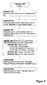
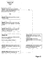
- the two procedures, as in the FIGS. 1 and 2 are provided for analysis of nitrogen (N) in a sample.
- a sample to be analyzed for its content of nitrogen (N) is provided.
- this sample is fed to an oxidation reactor and then, step 14, is burned with the introduction of helium (He) as the carrier gas and oxygen (O 2 ) as the reaction gas.
- He helium
- O 2 oxygen
- the combustion gases are removed from the oxidation reactor in the carrier gas stream, and in step 16, the nitrogen oxides (NO x ) present in this gas mixture are reduced to molecular nitrogen (N 2 ).
- gaseous matrix components are separated from the gas mixture (step 18).
- the gaseous matrix constituents are all gaseous constituents without the analyte, ie the total nitrogen (TN).
- the gas stream is dehumidified in a step 20.
- the halogens are removed and in a step 24, a CO 2 adsorption or absorption takes place.
- steps 20 through 24 While the illustrated sequence of steps 20 through 24 is preferred because, for example, the adsorbed CO 2 may be used for carbon analysis, the sequence of steps 20 through 24 may also be changed by step 22 prior to any of the substeps of step 20 , namely the membrane drying (sub-step 20b), is made.
- the stated sequence of steps 20a, 22, 20b, 20c and 24 has the advantage that the membrane unit used for drying (step 20b) is protected from aggressive halogen species.
- the purified gas mixture could then be subjected directly to process step 28 by detecting the molecular nitrogen (N 2 ) contained in the carrier gas.
- a process step 26 is carried out, in which the molecular nitrogen (N 2 ) contained in the carrier gas (He) is concentrated. This concentration achieves a symmetrical shape (no tailing, splitting, etc.) and a better focus of the peak, thereby achieving a better signal-to-noise ratio.
- TN total nitrogen
- N 2 molecular nitrogen
- TNb whole bound Nitrogen
- FIG. 1 is shown and described above, are process steps of the procedure of the FIG. 2 which correspond to the process steps of FIG. 1 denoted by the same reference numerals, supplemented by 100 or 200, respectively.
- the total bound nitrogen (TNb) remaining in the separation step 111 will be determined already on the basis of FIG. 1 explained method steps 112 to 128 (steps 12 to 28 in FIG. 1 ). However, the molecular nitrogen (N 2 ) detected in the process flow in step 128 goes back only to the molecular nitrogen (N 2 ) present in the bound nitrogen contained in the step 111 in bonded form (TNb).
- the proportion of molecular nitrogen (N 2 ) which was present in the aqueous sample in physically dissolved form should also be quantitatively determined
- the proportion of the dissolved molecular nitrogen (N 2 ) which is separated from the sample in method step 111 becomes Process steps 220,224 and 226 subjected.
- the process step module 218 (consisting of procedural documents 220 and 224) gaseous matrix components are separated or removed from the gas mixture, the gas mixture is dehumidified (step 220) and a CO 2 adsorption or absorption (Step 224).
- the step 226 again serves to concentrate the molecular nitrogen (N 2 ) contained in the carrier gas (He) before the detection (step 128).
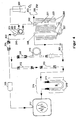
- the procedure, as it is in FIG. 1 can be shown with a device of FIG. 3 be performed.
- This device of FIG. 3 is in the FIG. 4 extended by a separation device, the process step 111 of the process flow of FIG. 2 is to be assigned.
- the device as in FIG. 3 is used to analyze nitrogen (N) in a sample
- the sample to be analyzed (an aqueous sample) is taken from a sample container 300 and injected at the top of a vertically oriented oxidation reactor 301 via an input head 302 into a sample crucible 303.
- the oxidation reactor 301 is heated by an oven 304 from the outside to temperatures up to 1200 ° C (typical combustion temperature 850 ° C).
- the sample is burned by supplying oxygen (O 2 ) via an oxygen supply 305, and the combustion components are discharged by supplying a carrier gas (helium (He)) through a carrier gas supply 306 both connected to the input head 302.
- a carrier gas helium (He)
- He carrier gas
- At the lower end of the oxidation reactor 301 is connected via a heated gas line 307 with a likewise heated from the outside, vertical reduction pipe 308.
- nitrogen oxides (NO x ) contained in the gas mixture carrier gas stream with residual oxygen, as well as analyte and matrix constituents
- N 2 molecular nitrogen
- the carrier gas stream is then fed to a separator 309 in the form of a condenser, in which the largest proportion of water is separated from the gas stream.
- the separating device 309 is followed by a further drying device 310 in order to further reduce the water content (moisture) in the gas stream.
- a drying device Preferably, a membrane drying is used, which has the advantage that it can be regenerated.
- the gas stream is fed to a further drying device 311 in the form of a chemical dryer. During chemical drying, the residual moisture is chemically bound.
- the chemical dryer 311 contains for this purpose phosphorus pentoxide on a support material.
- Another advantage of the chemical dryer 311 is the function as a visual indicator to monitor the functionality of all three functional units 309, 310 and 311 (water removal). This is made possible by an added indicator substance.
- the gas stream then passes through a halogen absorber 312 and a CO x adsorber or absorber 313.
- the halogen absorber 312 contains an absorber (eg silver wool), so that the halogen compounds, such as HCl, are chemically bonded.
- the adjoining CO 2 adsorbing or absorbing means 313 adsorbs or absorbs carbon dioxide (CO 2 ) contained in the gas stream;
- the CO 2 adsorption or absorption device 313 is filled with silica gel (adsorption) or NaOH on a support (absorption).
- the molecular nitrogen (N 2 ) still present in the gas stream is concentrated in a concentration unit 314.
- This concentration unit 314 comprises an adsorption tube 315 (optionally wrapped with a jacket resistance heater), which is cooled or also heated from the outside by one or more Peltier elements (s) 316.
- the adsorption tube 315 is first actively cooled so that the analyte (N 2 ) is adsorbed on the adsorber. After a sufficient adsorption time, the adsorption tube 315 becomes active, optionally only occupied by at least one Peltier element 316 for desorption, so that the concentrated molecular nitrogen (N 2 ) contained in the carrier gas (He) is then fed to a detector 317 ,
- thermoelectric element 316 instead of heating the adsorption tube 315 of the concentration unit for desorption of the concentrated nitrogen (N 2 ) by means of Peltier element 316, it would also be possible to use a resistance heater (not shown). However, the heating by means of Peltier element 316 has the advantage that both cooling and heating can be carried out with one and the same element. In addition, for heating the adsorption tube 315, a resistance heater may be used in addition to the Peltier element 316.
- FIG. 4 which will be described below, are all parts associated with the device of FIG. 3 are identical, denoted by the same reference numerals, so that a new description and explanation of these parts is largely not subsequently made. With regard to these parts, the above description of the FIG. 3 be resorted to.
- an aqueous sample in which the molecular nitrogen (N 2 ) attributable to the total nitrogen (TN) is to be distinguished from the total nitrogen (TNb) present in the sample is first supplied to a separator 318.
- This is preferably a so-called vacuum membrane separation device.
- the aqueous sample taken from the sample container 300 passes through a thin-walled membrane tube 319, which extends through a housing 320 which is at negative pressure relative to atmospheric pressure.
- the physically dissolved molecular nitrogen (N 2 ) diffuses into the housing 320 and is sucked out of the housing 320 via a pump 321.
- the sample stream containing the remaining nitrogen (TNb) is then fed from the separator 318 or from the membrane tube 319 to the oxidation reactor 301, as described in method steps 111 and 112 of FIG FIG. 2 corresponds to, and ultimately the detector 317 supplied, so that in the detector 317 that portion of the contained in the carrier gas molecular nitrogen (N 2 ) is analyzed, which is not present in the sample as physically dissolved molecular nitrogen (N 2 ).
- the from the separator 318 via the pump 321 and the gas line 322 drawn physically dissolved molecular nitrogen (N 2) is a purification module 324 led symbolically for a unit for the separation of gaseous matrix components from the gas mixture (Module 218) consisting of a dehumidifier (step 220) and a CO 2 adsorber or absorber (step 224).
- the dehumidifying device with the drying device 311 (optionally in combination with 310) and the CO 2 adsorption or absorption device with the device 313 are comparable.
- the molecular nitrogen (N 2 ) contained in the carrier gas stream is concentrated in a further concentration unit 325, and then the concentrated nitrogen (N 2 ) is desorption fed to the detector 317, which then only the proportion of the physically dissolved molecular contained in the sample Nitrogen (N 2 ) determined.
- the further concentration unit 325 preferably corresponds in its construction to the concentration unit 314 described above.
Landscapes
- Chemical & Material Sciences (AREA)
- Life Sciences & Earth Sciences (AREA)
- Health & Medical Sciences (AREA)
- Engineering & Computer Science (AREA)
- Biochemistry (AREA)
- Physics & Mathematics (AREA)
- Analytical Chemistry (AREA)
- Combustion & Propulsion (AREA)
- General Health & Medical Sciences (AREA)
- General Physics & Mathematics (AREA)
- Immunology (AREA)
- Pathology (AREA)
- Molecular Biology (AREA)
- Food Science & Technology (AREA)
- Medicinal Chemistry (AREA)
- Investigating Or Analyzing Non-Biological Materials By The Use Of Chemical Means (AREA)
Applications Claiming Priority (1)
| Application Number | Priority Date | Filing Date | Title |
|---|---|---|---|
| DE201410002266 DE102014002266B3 (de) | 2014-02-20 | 2014-02-20 | Verfahren und Vorrichtung zur Analyse von Stickstoff (N) in einer Probe |
Publications (1)
| Publication Number | Publication Date |
|---|---|
| EP2919005A1 true EP2919005A1 (fr) | 2015-09-16 |
Family
ID=52391784
Family Applications (1)
| Application Number | Title | Priority Date | Filing Date |
|---|---|---|---|
| EP15000148.5A Withdrawn EP2919005A1 (fr) | 2014-02-20 | 2015-01-20 | Procédé et dispositif destinés à l'analyse d'azote (n) dans un échantillon |
Country Status (2)
| Country | Link |
|---|---|
| EP (1) | EP2919005A1 (fr) |
| DE (1) | DE102014002266B3 (fr) |
Cited By (1)
| Publication number | Priority date | Publication date | Assignee | Title |
|---|---|---|---|---|
| WO2018171836A1 (fr) * | 2017-03-20 | 2018-09-27 | Taunus Instruments GmbH | Procédé pour déterminer une teneur en azote dans des échantillons solides ou liquides |
Families Citing this family (1)
| Publication number | Priority date | Publication date | Assignee | Title |
|---|---|---|---|---|
| CN110208319B (zh) * | 2019-06-05 | 2022-03-04 | 北京诺德泰科仪器仪表有限公司 | 一种杜马斯定氮仪反应管 |
Citations (5)
| Publication number | Priority date | Publication date | Assignee | Title |
|---|---|---|---|---|
| DE2025390A1 (de) | 1969-06-18 | 1971-01-28 | Balzers + Pfeiffer Hochvakuum GmbH, 6000 Frankfurt | Verfahren zur quantitativen Bestimmung der in den einzelnen chemischen Verbindungen eines Stoffgemisches enthaltenden Elemente bzw Isotopen |
| DE3538778A1 (de) | 1985-10-31 | 1987-05-07 | Heraeus Gmbh W C | Verfahren und vorrichtung zum bestimmen des gehalts an stickstoff in einer probe |
| DE19708179A1 (de) | 1997-02-28 | 1998-09-10 | Elementar Analysensysteme Gmbh | Reduktionsrohr zur Stickstoffbestimmung bei der Elementaranalyse |
| DE60015706T2 (de) * | 2000-01-04 | 2005-12-15 | Ceca S.A. | Lithium ausgetauschten Zeolithen ,Verfahren zu ihrer Herstellung und ihre Verwendung als Absorptionsmittel für Stickstoff bei der Luftzerlegung |
| DE102010032396A1 (de) * | 2010-07-27 | 2012-02-02 | Elementar Analysensysteme Gmbh | Verfahren und Vorrichtung zur Bestimmung der Isotopenverhältnisse von Kohlenstoff in Wasserproben |
-
2014
- 2014-02-20 DE DE201410002266 patent/DE102014002266B3/de not_active Withdrawn - After Issue
-
2015
- 2015-01-20 EP EP15000148.5A patent/EP2919005A1/fr not_active Withdrawn
Patent Citations (5)
| Publication number | Priority date | Publication date | Assignee | Title |
|---|---|---|---|---|
| DE2025390A1 (de) | 1969-06-18 | 1971-01-28 | Balzers + Pfeiffer Hochvakuum GmbH, 6000 Frankfurt | Verfahren zur quantitativen Bestimmung der in den einzelnen chemischen Verbindungen eines Stoffgemisches enthaltenden Elemente bzw Isotopen |
| DE3538778A1 (de) | 1985-10-31 | 1987-05-07 | Heraeus Gmbh W C | Verfahren und vorrichtung zum bestimmen des gehalts an stickstoff in einer probe |
| DE19708179A1 (de) | 1997-02-28 | 1998-09-10 | Elementar Analysensysteme Gmbh | Reduktionsrohr zur Stickstoffbestimmung bei der Elementaranalyse |
| DE60015706T2 (de) * | 2000-01-04 | 2005-12-15 | Ceca S.A. | Lithium ausgetauschten Zeolithen ,Verfahren zu ihrer Herstellung und ihre Verwendung als Absorptionsmittel für Stickstoff bei der Luftzerlegung |
| DE102010032396A1 (de) * | 2010-07-27 | 2012-02-02 | Elementar Analysensysteme Gmbh | Verfahren und Vorrichtung zur Bestimmung der Isotopenverhältnisse von Kohlenstoff in Wasserproben |
Non-Patent Citations (1)
| Title |
|---|
| BRIAN FRY ET AL: "Cryoflow: Cryofocusing Nanomole Amounts of CO2, N2, and SO2 from an Elemental Analyzer for Stable Isotopic Analysis", RAPID COMMUNICATIONS IN MASS SPECTROMETRY, JOHN WILEY & SONS, GB, vol. 10, no. 8, 4 December 1998 (1998-12-04), pages 953 - 958, XP007919671, ISSN: 0951-4198, DOI: 10.1002/(SICI)1097-0231(19960610)10:8<953::AID-RCM534>3.0.CO;2-0 * |
Cited By (1)
| Publication number | Priority date | Publication date | Assignee | Title |
|---|---|---|---|---|
| WO2018171836A1 (fr) * | 2017-03-20 | 2018-09-27 | Taunus Instruments GmbH | Procédé pour déterminer une teneur en azote dans des échantillons solides ou liquides |
Also Published As
| Publication number | Publication date |
|---|---|
| DE102014002266B3 (de) | 2015-03-19 |
Similar Documents
| Publication | Publication Date | Title |
|---|---|---|
| DE69023446T2 (de) | Verfahren und Vorrichtung zur Dosierung von Verunreinigungen in einem Gas durch Gaschromatographie und Anwendung zur Kalibrierung von dotierenden Verunreinigungen in Silan. | |
| DE69634022T2 (de) | Verbessertes Verfahren zur Festphasenmikroextraktion von Spuren organischer Analyten | |
| DE102010032396A1 (de) | Verfahren und Vorrichtung zur Bestimmung der Isotopenverhältnisse von Kohlenstoff in Wasserproben | |
| DE3009069C2 (de) | Eingangs-Kopf eines Meß/Nachweissystems für chemische Agentien | |
| EP1707253B1 (fr) | Procédé et dispositif destinés à la détermination de rapports isotopiques d'éléments légers en une étape | |
| DE112019006354T5 (de) | Automatisiertes system zur fern-inline-konzentration und homogenisierung extrem niedriger konzentrationen in reinen chemikalien | |
| DE102017004633A1 (de) | Elementaranalysesystem und -verfahren | |
| DE602004004369T2 (de) | Verfahren zur analyse von verunreinigungen in einem prozessfluidstrom | |
| EP1143234B1 (fr) | Procédé et appareil de dépistage du mercure | |
| DE2902056A1 (de) | Verfahren und vorrichtung zur bestimmung des gesamtstickstoffgehalts in waessrigen systemen | |
| DE112009001241T5 (de) | Verfahren und Vorrichtung zur Analyse von Poly(biphenylchlorid) in elektrischem Isolieröl | |
| DE102010039275B4 (de) | Verfahren und Vorrichtung zur online-Bestimmung des Isotopenverhältnisses von Chlor, Brom oder Schwefel in einer organischen Probe | |
| DE102014002266B3 (de) | Verfahren und Vorrichtung zur Analyse von Stickstoff (N) in einer Probe | |
| DE2944774A1 (de) | Verfahren und vorrichtung zur entnahme und analyse von luftproben | |
| EP0278096A2 (fr) | Procédé pour la surveillance continue d'émissions et d'immissions de mercure | |
| DE102006021333B4 (de) | Verbessertes Verfahren zur qualitativen und/oder quantitativen Bestimmung geringer Konzentrationen an organischen Spurenstoffen in wäßrigen Systemen und eine Analysevorrichtung zur Durchführung dieses Verfahrens | |
| DE69228519T2 (de) | Verfahren und Vorrichtung zur analytischen Bestimmung von Halogenen,Schwetel undPhosphor | |
| EP2047233A1 (fr) | Collecteur de mercure activé et procédé de détermination sélective d'espèces de mercure | |
| DE102007054419A1 (de) | Verfahren und Vorrichtung zur Isotopenverhältnisanalyse | |
| DE102007033906A1 (de) | Verfahren zur Analyse von Gasen, insbesondere zur Analyse der menschlichen Ausatemluft | |
| DE102015122506A1 (de) | Verfahren und Vorrichtung zur Bestimmung eines Anteils eines Elements in einer Probe | |
| EP1831680B1 (fr) | Procédé d'analyse élémentaire d'un échantillon organique libéré par combustion, et dispositif correspondant | |
| AT412240B (de) | Verfahren und vorrichtung zur überwachung und bestimmung von organischen spurenkomponenten in einem gasstrom | |
| EP0360901A1 (fr) | Procédé et dispositif d'échantillonnage et d'analyse d'hydrocarbures | |
| DE60207377T2 (de) | Verfahren zur konzentrationsmessung von verunreinigungen in helium durch ionenmobilitäts-spektrometrie |
Legal Events
| Date | Code | Title | Description |
|---|---|---|---|
| PUAI | Public reference made under article 153(3) epc to a published international application that has entered the european phase |
Free format text: ORIGINAL CODE: 0009012 |
|
| AK | Designated contracting states |
Kind code of ref document: A1 Designated state(s): AL AT BE BG CH CY CZ DE DK EE ES FI FR GB GR HR HU IE IS IT LI LT LU LV MC MK MT NL NO PL PT RO RS SE SI SK SM TR |
|
| AX | Request for extension of the european patent |
Extension state: BA ME |
|
| 17P | Request for examination filed |
Effective date: 20160315 |
|
| RBV | Designated contracting states (corrected) |
Designated state(s): AL AT BE BG CH CY CZ DE DK EE ES FI FR GB GR HR HU IE IS IT LI LT LU LV MC MK MT NL NO PL PT RO RS SE SI SK SM TR |
|
| 17Q | First examination report despatched |
Effective date: 20160418 |
|
| STAA | Information on the status of an ep patent application or granted ep patent |
Free format text: STATUS: THE APPLICATION HAS BEEN WITHDRAWN |
|
| 18W | Application withdrawn |
Effective date: 20190603 |