EP2919036A1 - Vorrichtung und verfahren für spektrale computertomografie - Google Patents
Vorrichtung und verfahren für spektrale computertomografie Download PDFInfo
- Publication number
- EP2919036A1 EP2919036A1 EP15161248.8A EP15161248A EP2919036A1 EP 2919036 A1 EP2919036 A1 EP 2919036A1 EP 15161248 A EP15161248 A EP 15161248A EP 2919036 A1 EP2919036 A1 EP 2919036A1
- Authority
- EP
- European Patent Office
- Prior art keywords
- energy
- radiation
- detector
- technique
- received
- Prior art date
- Legal status (The legal status is an assumption and is not a legal conclusion. Google has not performed a legal analysis and makes no representation as to the accuracy of the status listed.)
- Withdrawn
Links
- 238000002591 computed tomography Methods 0.000 title claims abstract description 22
- 238000000034 method Methods 0.000 title claims description 54
- 230000003595 spectral effect Effects 0.000 title description 7
- 230000005855 radiation Effects 0.000 claims abstract description 73
- 230000006870 function Effects 0.000 claims description 24
- 238000005259 measurement Methods 0.000 claims description 15
- 238000006243 chemical reaction Methods 0.000 claims description 8
- 230000005865 ionizing radiation Effects 0.000 claims description 5
- 238000004891 communication Methods 0.000 claims description 4
- 238000000691 measurement method Methods 0.000 claims description 4
- 230000008859 change Effects 0.000 claims description 2
- 230000003993 interaction Effects 0.000 claims description 2
- 230000007246 mechanism Effects 0.000 description 19
- 239000000463 material Substances 0.000 description 13
- 229910003016 Lu2SiO5 Inorganic materials 0.000 description 4
- 230000003287 optical effect Effects 0.000 description 4
- 238000001514 detection method Methods 0.000 description 3
- 238000000926 separation method Methods 0.000 description 3
- 230000004075 alteration Effects 0.000 description 2
- 230000008901 benefit Effects 0.000 description 2
- QWUZMTJBRUASOW-UHFFFAOYSA-N cadmium tellanylidenezinc Chemical compound [Zn].[Cd].[Te] QWUZMTJBRUASOW-UHFFFAOYSA-N 0.000 description 2
- 238000010586 diagram Methods 0.000 description 2
- 230000000694 effects Effects 0.000 description 2
- 238000012986 modification Methods 0.000 description 2
- 230000004048 modification Effects 0.000 description 2
- 238000002600 positron emission tomography Methods 0.000 description 2
- 230000004044 response Effects 0.000 description 2
- 230000035945 sensitivity Effects 0.000 description 2
- 238000002603 single-photon emission computed tomography Methods 0.000 description 2
- XUIMIQQOPSSXEZ-UHFFFAOYSA-N Silicon Chemical compound [Si] XUIMIQQOPSSXEZ-UHFFFAOYSA-N 0.000 description 1
- 238000002083 X-ray spectrum Methods 0.000 description 1
- 238000004458 analytical method Methods 0.000 description 1
- 210000003484 anatomy Anatomy 0.000 description 1
- 229910052797 bismuth Inorganic materials 0.000 description 1
- JCXGWMGPZLAOME-UHFFFAOYSA-N bismuth atom Chemical compound [Bi] JCXGWMGPZLAOME-UHFFFAOYSA-N 0.000 description 1
- 230000001143 conditioned effect Effects 0.000 description 1
- 239000002872 contrast media Substances 0.000 description 1
- 238000012937 correction Methods 0.000 description 1
- 238000013461 design Methods 0.000 description 1
- 238000002059 diagnostic imaging Methods 0.000 description 1
- 238000012850 discrimination method Methods 0.000 description 1
- 230000009977 dual effect Effects 0.000 description 1
- 230000004907 flux Effects 0.000 description 1
- 238000003384 imaging method Methods 0.000 description 1
- 230000006872 improvement Effects 0.000 description 1
- 230000000977 initiatory effect Effects 0.000 description 1
- 238000007689 inspection Methods 0.000 description 1
- BOYZAERJCXIRAX-UHFFFAOYSA-N lutetium(3+);trisilicate Chemical compound [Lu+3].[Lu+3].[Lu+3].[Lu+3].[O-][Si]([O-])([O-])[O-].[O-][Si]([O-])([O-])[O-].[O-][Si]([O-])([O-])[O-] BOYZAERJCXIRAX-UHFFFAOYSA-N 0.000 description 1
- 238000009659 non-destructive testing Methods 0.000 description 1
- 238000009206 nuclear medicine Methods 0.000 description 1
- 230000001151 other effect Effects 0.000 description 1
- 230000008569 process Effects 0.000 description 1
- 238000012545 processing Methods 0.000 description 1
- 239000004065 semiconductor Substances 0.000 description 1
- 229910052710 silicon Inorganic materials 0.000 description 1
- 239000010703 silicon Substances 0.000 description 1
- FVAUCKIRQBBSSJ-UHFFFAOYSA-M sodium iodide Chemical compound [Na+].[I-] FVAUCKIRQBBSSJ-UHFFFAOYSA-M 0.000 description 1
- 238000001228 spectrum Methods 0.000 description 1
- 238000012360 testing method Methods 0.000 description 1
Images


Classifications
-
- G—PHYSICS
- G01—MEASURING; TESTING
- G01T—MEASUREMENT OF NUCLEAR OR X-RADIATION
- G01T1/00—Measuring X-radiation, gamma radiation, corpuscular radiation, or cosmic radiation
- G01T1/16—Measuring radiation intensity
- G01T1/161—Applications in the field of nuclear medicine, e.g. in vivo counting
- G01T1/164—Scintigraphy
- G01T1/1641—Static instruments for imaging the distribution of radioactivity in one or two dimensions using one or several scintillating elements; Radio-isotope cameras
- G01T1/1644—Static instruments for imaging the distribution of radioactivity in one or two dimensions using one or several scintillating elements; Radio-isotope cameras using an array of optically separate scintillation elements permitting direct location of scintillations
-
- G—PHYSICS
- G01—MEASURING; TESTING
- G01T—MEASUREMENT OF NUCLEAR OR X-RADIATION
- G01T1/00—Measuring X-radiation, gamma radiation, corpuscular radiation, or cosmic radiation
- G01T1/29—Measurement performed on radiation beams, e.g. position or section of the beam; Measurement of spatial distribution of radiation
- G01T1/2914—Measurement of spatial distribution of radiation
- G01T1/2985—In depth localisation, e.g. using positron emitters; Tomographic imaging (longitudinal and transverse section imaging; apparatus for radiation diagnosis sequentially in different planes, steroscopic radiation diagnosis)
Definitions
- the present application relates to the field of spectral computed tomography (CT). It also relates to the detection of x-rays and other radiation where it is desirable to obtain information regarding the energy or energy spectra of the detected radiation. It finds particular application in medical imaging, and also has application in non-destructive testing and analysis, security applications, and other applications where energy discrimination capabilities are useful.
- CT computed tomography
- CT systems have provided image data representative of the x-ray attenuation of an object under examination, such systems have been limited in their ability to provide information about the material composition of the object, especially where different materials have had similar radiation attenuations. Improving the material separation capability of a CT system can, however, be useful in a number of applications. In medical applications, for example, it may be desirable to distinguish between various tissue types, to distinguish tissue from contrast agent, and the like. As another example, information on the composition of a sample can simplify the inspection task in security applications.
- detector efficiency Another factor which influences the performance of a CT system is detector efficiency, as the quality of the resultant images is ordinarily a function of the efficiency with which the available x-ray flux is detected and utilized. Viewed from another perspective, improving detector efficiency helps reduce the dose needed to obtain images of a suitable quality.
- One way to obtain material composition information is to measure the x-ray attenuation of the object at different x-ray energies or energy ranges, for example by using detectors having spectral capabilities.
- detectors have included multiple scintillator layers (or direct conversion layers), with the respective layer selected to have a different energy response.
- this method tends to have relatively limited energy resolutions and often have partially overlapping spectral responses, thus limiting the energy resolution of the detector output signals.
- Photon counting detectors which have been used in nuclear medicine applications such as single photon emission computed tomography (SPECT) and positron emission tomography (PET), have included scintillator-based detectors such as those based on lutetium orthosilicate (Lu 2 SiO 5 or LSO), bismuth germanate (BGO) and sodium iodide (NaI) together with a photodetectors such as photomultiplier tubes (PMTs). Still other scintillator materials such as Gd 2 SiO 5 (GSO), LuAlO 3 (LuAP) and YAlO 3 (YAP) are also known. Direct conversion detectors such as cadmium zinc telluride (CZT) have also been used.
- CZT cadmium zinc telluride
- photon counting detectors have a relatively greater sensitivity than traditional CT detectors. Moreover, photon counting detectors can also be used to obtain information about the energy distribution of the detected radiation, which has been used in SPECT and PET applications for useful purposes such as correcting for the effects of scatter. Unfortunately, however, photon counting detectors are not particularly well-suited for use at the count rates typically encountered in CT applications. In particular, these relatively higher count rates can lead to pulse pileups and other effects which serve, among other things, to limit the detector energy resolution.
- an x-ray computed tomography apparatus includes an energy discriminating x-ray measurement system which employs first and second different energy measurement techniques to measure an energy of x-radiation received by a detector.
- the apparatus also includes a combiner which combines energy measurements generated using the first and second techniques to produce an output indicative of the energy of the received x-radiation.
- the first technique classifies the received radiation into at least first and second energy ranges and the second technique sub-classifies the classified radiation as a function of its energy.
- a computed tomography method includes using a second energy classification technique to sub-classify radiation classified by a first energy classification technique, combining the sub-classified radiation to generate an output indicative of the energy of radiation received by a radiation sensitive detector, and repeating the steps of using the second technique and combining for each of a plurality of reading times.
- the first and second energy classification techniques are different.
- the first technique classifies the received radiation into three or fewer ranges, and wherein the number of ranges is an integer.
- using a first technique includes using at least first and second scintillators to classify the received radiation.
- the first scintillator has a decay time constant of less than about 40ns.
- using a second technique includes using a photon counting detector.
- using a second technique includes using an energy resolving photon counter.
- the method includes correcting for pulse pileups.
- the method further includes the step of reconstructing radiation received at a plurality of projection angles to generate volumetric data indicative of an object under examination.
- an apparatus includes a first energy discriminator which uses a first measurement technique to measure an energy of ionizing radiation received by a radiation sensitive detector, and a combiner which uses the first energy measurement and a second energy measurement obtained using a second, different energy measurement technique to produce, for each a plurality of reading times, a first output indicative of received radiation having a first relatively lower energy level and a second output indicative of received radiation having a second relatively higher energy level.
- the first energy discriminator includes an energy resolving photon counter.
- the apparatus includes an x-ray tube which generates the received radiation.
- the reading times are less than about 0.3ms in length.
- an apparatus includes a first ionizing radiation detector sensitive to radiation having a first energy, a second ionizing radiation detector sensitive to radiation having a second energy, a first energy resolving photon counter operatively connected to the first radiation detector, a second energy resolving photon counter operatively connected to the second radiation detector, and a combiner which combines signals from the first and second energy resolving photon counters to generate a first output indicative of radiation having a first relatively lower energy and a second output indicative of radiation having a second relatively higher energy.
- the first radiation detector includes a first scintillator and the second radiation detector includes a second scintillator.
- the apparatus includes a radiation receiving face and the first scintillator is disposed physically between the second scintillator and the radiation receiving face, whereby the second scintillator receives radiation which has passed through the first scintillator.
- the apparatus includes a pulse pileup corrector operatively connected to an output of the first energy resolving photon counter.
- the first radiation detector includes a direct conversion detector.
- the invention may take form in various components and arrangements of components, and in various steps and arrangements of steps.
- the drawings are only for purposes of illustrating the preferred embodiments and are not to be construed as limiting the invention.
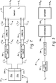
- a CT scanner includes a rotating gantry 18 which rotates about an examination region 14.
- the gantry 18 supports an x-ray source 12 such as an x-ray tube.
- the gantry 18 also supports an x-ray sensitive detector 20 which subtends an arc on the opposite side of the examination region 14.
- X-rays produced by the x-ray source 12 traverse the examination region 14 and are detected by the detector 20.
- the scanner 10 generates projection data indicative of the radiation attenuation along a plurality of projections or rays through an object disposed in the examination region 14.
- the detector 20 includes a plurality of detector elements 100 disposed in an arcuate array extending in the transverse and longitudinal directions. As will be described in further detail below, the detector elements 100 and the associated signal processing chain cooperate to measure the energy of the received radiation using at least two (2) different energy measurement mechanisms or techniques.
- the detectors include at least first and second scintillator layers, with respective photon counting detectors in optical communication with each.
- the x-ray source 12 Depending on the configuration of the scanner 10 and the detector 20, the x-ray source 12 generates a generally fan, wedge, or cone shaped radiation beam which is approximately coextensive with the coverage of the detector 20. Moreover, so-called fourth generation scanner configurations in which the detector 20 spans an arc of 360 degrees and remains stationary while the x-ray source 12 rotates about the examination region, flat panel detectors, and single slice detectors may also be implemented. In the case of a multidimensional array, the various detector elements 100 maybe focused at the x-ray source 12 focal spot and hence form a section of a sphere.
- An object support 16 such as a couch supports a patient or other object in the examination region 14.
- the support 16 is preferably movable in coordination with a scan in order to provide a helical, axial, circle and line, or other desired scanning trajectory.
- a data measurement system 23 preferably located on or near the rotating gantry 18 receives signals originating from the various detector elements 100 and provides necessary analog to digital conversion, multiplexing, interface, data communication, and similar functionality.
- the system also includes a plurality of energy resolving photon counters 26a, 26b ... 26n, a corresponding plurality of optional correctors 24a, 24b ... 24n, and a combiner 30 which cooperate to provide outputs E L , E H indicative of the radiation detected at respective first and second energy ranges or windows.
- the outputs E L , E H are advantageously obtained for each of a plurality of reading periods corresponding to various projection angles about the examination region 14.
- the time period over which a reading is obtained is a function of a number of design considerations, such as the sensitivity of the detectors, the desired transverse resolution, the gantry rotation speed, and the like.
- a suitable reading period can be on the order of 0.1 to 0.5 milliseconds (ms), although other reading periods can be implemented.
- counters 26, correctors 24, and combiners 30 are advantageously provided for other detector elements 100 for which similar energy discrimination capabilities are desired.
- the reconstructor 22 reconstructs the projection data to generate volumetric data indicative of the interior anatomy of the patient.
- the data from the various energy ranges is processed (before reconstruction, after reconstruction, or both) to provide information about the material composition of the object under examination.
- a controller 28 coordinates the x-ray source 12 parameters such as tube voltage and current, movement of the patient couch 16, operation of the data measurement system 23, and/or other operating parameters as necessary to carry out a desired scan protocol.
- a general purpose computer serves an operator console 44.
- the console 44 includes a human-readable output device such as a monitor or display and an input device such as a keyboard and/or mouse.
- Software resident on the console allows the operator to control the operation of the scanner by establishing desired scan protocols, initiating and terminating scans, viewing and otherwise manipulating the volumetric image data, and otherwise interacting with the scanner.
- FIGURE 2 the energy resolving photon counters 26a, 26b, correctors 24a, 24b, and combiner 30 will be described in greater detail in connection with an exemplary detector element 100 having first 202a and second 202b scintillator layers and corresponding first 204a and second 204b optical photon detectors suitable for photon counting methods.
- the first scintillator layer 202a which is closer to the radiation receiving face of the detector 100 and to the x-ray source 12, is fabricated from such material type and thickness which absorbs the softer or lower energy x-radiation 206.
- the second scintillator layer 202b is disposed behind the first scintillator 202a relatively farther from the x-ray source 12, and is fabricated from a material type and thickness which absorbs radiation which has passed through the first scintillator 202a, which radiation tends to be harder or higher in energy.
- One example of such a structure is disclosed in Altman, et al. entitled Double Decker Detector for Spectral CT , U.S. Patent Application Serial Number 60/674,900, filed on April 26, 2005 and PCT/IB2006/051061, filed on April 10, 2006 , which applications are co-pending and commonly owned with the present application and are expressly incorporated by reference in their entirety herein.
- a first optical photon detector 204a receives light signals from the first scintillator 202a generates a detector signal D L indicative of a first relatively lower energy range.
- a second optical photon detector 204b receives light signals from the second scintillator 202b and generates a detector signal D H indicative of a second relatively higher energy range.
- the first and second energy ranges are a function of the materials and thicknesses selected for the scintillators 202 and are typically characterized by a limited energy resolution.
- the scintillators 202 are advantageously fabricated from relatively fast scintillator materials such as Lu 2 SiO 5 (LSO), Lu 1.8 Y 0.2 SiO 5 (LYSO), Gd 2 SiO 5 (GSO), LuAlO 3 (LuAP) or YAlO 3 (YAP). These scintillators have rise time constants on the order of 1 nanosecond (ns) and respective decay time constants of approximately 40ns, 40ns, 40ns, 18ns, and 24ns.
- the photon counting detectors are advantageously implemented using photosensors such as photomultiplier tubes, photodiodes, Geiger mode avalanche photodiodes (GM-APDs), silicon photomultipliers (SiPM), or the like.
- the energy resolving counters 26 apply photon counting techniques to exploit the energy information provided by the detectors 204.
- the first energy resolving counter 26a further classifies the relatively lower energy detector signal D L into first and second energy windows, generating a first output signal R LL indicative of a relatively lower energy range and a second output signal R LH indicative of a higher energy range.
- the second energy resolving counter 26b likewise further classifies the relatively higher energy detector signal D H into first and second energy windows, generating a first output signal R HL indicative of a relatively lower energy range and a second output signal R HH indicative of a relatively higher energy range. Consequently, the apparatus employs two distinct energy separation mechanisms: a first mechanism which exploits the energy ranges of the respective scintillator and a second mechanism which exploits the energy resolving capabilities of the photon counting detectors.
- the photon resolving counters 26 relies on the rate of change of the detector signals D X to estimate the energy of the detected radiation. More particularly, the photon resolving counters 26 include a signal conditioner 302 which filters or otherwise conditions the signals D X from a detector, a differentiator 304 whose output value varies as a function of the rise time and the amplitude of the conditioned signals, a discriminator 306 which classifies the detected photons into two or more energy ranges or windows, and a counter or integrator 308 which produces output signals R XL and R XH indicative of the number and energy of the detected x-ray photons.
- a signal conditioner 302 which filters or otherwise conditions the signals D X from a detector
- a differentiator 304 whose output value varies as a function of the rise time and the amplitude of the conditioned signals
- a discriminator 306 which classifies the detected photons into two or more energy ranges or windows
- a counter or integrator 308 which
- optional correctors 24 correct for the effects of pileups on the signals R XL and R XH from the counter 26. More particularly, the correctors 24 weight the signals R XL and R XH as function of the count rate to account for high count rate situations in which the counter 26 is relatively more likely to incorrectly classify the detector signals D X into a higher energy window.
- Such energy resolving photon counters 26 and correctors 24 are described more fully in Carmi, Dual Energy Window X-ray CT with Photon Counting Detectors, U.S. patent application serial number 60/596,894 filed October 28, 2005 , which application is co-pending and commonly owned with the present application and is expressly incorporated by reference herein.
- One advantage of the described photon counting technique is that it is particularly well suited to CT and other relatively high count rate applications.
- the combiner 30 combines the signals C LL , C LH , C HL , C HH from the correctors 24a, 24b to generate output signals E H , E L indicative of the number of photons detected in respective higher and lower energy ranges or windows.
- the combiner includes four inputs A, B, C, and D as described in Table 1: Table 1 Input Description
- a Both the first (e.g., scintillator) and second (e.g., photon counting) energy discrimination mechanisms classify the event as belonging to a lower energy window.
- the first energy discrimination mechanism classifies the event as belonging to a lower energy window while the second energy discrimination mechanism classifies the event as belonging to a higher energy window.
- the first energy discrimination mechanism classifies the event as belonging to a higher energy window while the second energy discrimination mechanism classifies the event as belonging to a lower energy window.
- D Both the first (e.g., scintillator) and second (e.g., photon counting) energy discrimination mechanisms classify the event as belonging to a higher energy window.
- situation A it can reasonably be expected that the event falls within the lower output energy window.
- situation D it can likewise reasonably be expected that the event falls within the higher output energy window.
- situations B and C however, the situation is less clear.
- the combiner 30 combines the input signals A, B, C, and D to produce output signals E L and E H indicative of the radiation detected at respective higher and lower energy windows.
- the optimal weighting factor tends to be on the side of the discrimination method with the higher accuracy.
- the weighting parameters W 1 and W 2 are advantageously established as grater then 0.5 (e.g. 0.58) where the exact value can be determined empirically, for example through a calibration process. (again assuming equal values).
- input B will contribute to E L less than its contribution to E H .
- Input C will contribute to E L more than its contribution to E H .
- FIGURE 4 For the case of an exemplary detector 100 having three (3) energy levels.
- a suitable combination function is shown in Table 3: Table 3 Output E L Output E H Input A 1 0 Input B 1-W 1 W 1 Input G W 3 1-W 3 Input H 1-W 4 W 4 Input C W 2 1-W 2 Input D 0 1
- the scintillators need not be stacked in relation to the x-ray source 12 as shown generally in FIGURES 2 and 4 and may detect radiation which has traversed different paths.
- the photodetectors 204 need not be located laterally of the x-ray 206 direction. Semiconductor or other direct conversion detectors which produce the requisition information may also be used.
- the multiple radiation detection layers 202 (whether they are scintillators or direct conversion materials) is that the count rate of the various signals D X is relatively reduced
- other energy discrimination techniques may also be used.
- energy discrimination mechanisms other than the use of multiple detection layers and pulse counting are also contemplated.
- the described techniques are also applicable to the measurement of x-radiation in other than CT applications and also to the measurement of radiation other than x-radiation.
- the photon counters 26, the correctors 24, and combiner 30 may be implemented in hardware or software.
- the correctors 24 and combiner 30 may also be implemented by the reconstructor 22, as part of the data measurement system 23, or otherwise. Where the various functions are implemented via software, instructions which cause a computer processor to carry out the described techniques are advantageously stored on a computer readable storage medium accessible to the processor.
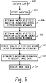
- FIGURE 5 Operation will now be described in relation FIGURE 5 for the exemplary embodiment of FIGURES 1 and 2 .
- a scan is initiated at 502.
- first energy discrimination mechanism is used to determine the energy of detected radiation.
- first 202a and second scintillators 202b provide outputs indicative of the radiation detected at first and second energy ranges.
- the energy ranges may be at least partially overlapping.
- a second energy discrimination mechanism is used to determine the energy of detected radiation.
- a photon counting technique is used to further classify the radiation into two or more energy ranges.
- the results of first and second energy discriminations are combined to generate outputs indicative of the radiation detected at first energies or energy windows using a desired combination function. Note that such outputs are provided for each of a plurality of reading periods indicative of various projection angles about the examination region 14. It should also be noted that the energy separation of the combined mechanisms is ordinarily superior to that which would be obtained by either mechanism operating independently.
- radiation information obtained at a plurality of projection angles is reconstructed to generate image data indicative of the radiation detected in the one or more energy ranges.
- the signals from two or more energy ranges may also be combined to generate image data indicative of the combined energy ranges.
- the image data is presented in a human readable form, for example on a monitor associated with the operator console 44.
Landscapes
- Physics & Mathematics (AREA)
- Health & Medical Sciences (AREA)
- Spectroscopy & Molecular Physics (AREA)
- Life Sciences & Earth Sciences (AREA)
- Molecular Biology (AREA)
- High Energy & Nuclear Physics (AREA)
- General Physics & Mathematics (AREA)
- Nuclear Medicine, Radiotherapy & Molecular Imaging (AREA)
- Optics & Photonics (AREA)
- Biomedical Technology (AREA)
- Medical Informatics (AREA)
- General Health & Medical Sciences (AREA)
- Engineering & Computer Science (AREA)
- Apparatus For Radiation Diagnosis (AREA)
- Measurement Of Radiation (AREA)
- Analysing Materials By The Use Of Radiation (AREA)
Applications Claiming Priority (2)
| Application Number | Priority Date | Filing Date | Title |
|---|---|---|---|
| US82183606P | 2006-08-09 | 2006-08-09 | |
| EP07813219.8A EP2052279B1 (de) | 2006-08-09 | 2007-07-23 | Vorrichtung und verfahren für spektrale computertomographie |
Related Parent Applications (2)
| Application Number | Title | Priority Date | Filing Date |
|---|---|---|---|
| EP07813219.8A Division-Into EP2052279B1 (de) | 2006-08-09 | 2007-07-23 | Vorrichtung und verfahren für spektrale computertomographie |
| EP07813219.8A Division EP2052279B1 (de) | 2006-08-09 | 2007-07-23 | Vorrichtung und verfahren für spektrale computertomographie |
Publications (1)
| Publication Number | Publication Date |
|---|---|
| EP2919036A1 true EP2919036A1 (de) | 2015-09-16 |
Family
ID=38788715
Family Applications (2)
| Application Number | Title | Priority Date | Filing Date |
|---|---|---|---|
| EP07813219.8A Active EP2052279B1 (de) | 2006-08-09 | 2007-07-23 | Vorrichtung und verfahren für spektrale computertomographie |
| EP15161248.8A Withdrawn EP2919036A1 (de) | 2006-08-09 | 2007-07-23 | Vorrichtung und verfahren für spektrale computertomografie |
Family Applications Before (1)
| Application Number | Title | Priority Date | Filing Date |
|---|---|---|---|
| EP07813219.8A Active EP2052279B1 (de) | 2006-08-09 | 2007-07-23 | Vorrichtung und verfahren für spektrale computertomographie |
Country Status (6)
| Country | Link |
|---|---|
| US (1) | US8243874B2 (de) |
| EP (2) | EP2052279B1 (de) |
| JP (2) | JP2010500119A (de) |
| CN (2) | CN101501526A (de) |
| RU (1) | RU2437118C2 (de) |
| WO (1) | WO2008021663A2 (de) |
Families Citing this family (41)
| Publication number | Priority date | Publication date | Assignee | Title |
|---|---|---|---|---|
| JP5582514B2 (ja) * | 2008-02-29 | 2014-09-03 | ジーイー・メディカル・システムズ・グローバル・テクノロジー・カンパニー・エルエルシー | X線ct装置 |
| JP5701743B2 (ja) * | 2008-03-19 | 2015-04-15 | コーニンクレッカ フィリップス エヌ ヴェ | 放射線検出器、画像システム、光子を検出するための方法及びその方法を実行するコンピュータプログラム |
| CN102119342A (zh) | 2008-08-13 | 2011-07-06 | 皇家飞利浦电子股份有限公司 | 用于探测低和高x射线通量的方法和装置 |
| US8410776B2 (en) * | 2009-09-28 | 2013-04-02 | Siemens Medical Solutions Usa, Inc. | Detector module for an emission tomography scanner |
| US9000385B2 (en) | 2009-12-30 | 2015-04-07 | General Electric Company | Method and apparatus for acquiring radiation data |
| WO2013095706A1 (en) * | 2011-12-21 | 2013-06-27 | Carestream Health, Inc. | Dental imaging with photon-counting detector |
| DE102011077859B4 (de) | 2011-06-21 | 2014-01-23 | Siemens Aktiengesellschaft | Quantenzählender Strahlungsdetektor |
| JP6215202B2 (ja) * | 2011-08-05 | 2017-10-18 | パルセータ, エルエルシーPulsetor, Llc | 密接に結合したシンチレータ−光電子増倍管の1又は複数の組合体を含む電子検出器及びそれを使用した電子顕微鏡 |
| JP5917157B2 (ja) * | 2012-01-13 | 2016-05-11 | 株式会社東芝 | X線ct装置 |
| US9069092B2 (en) * | 2012-02-22 | 2015-06-30 | L-3 Communication Security and Detection Systems Corp. | X-ray imager with sparse detector array |
| CN103308535B (zh) * | 2012-03-09 | 2016-04-13 | 同方威视技术股份有限公司 | 用于射线扫描成像的设备和方法 |
| DE102012216269A1 (de) * | 2012-09-13 | 2014-03-13 | Siemens Aktiengesellschaft | Röntgensystem und Verfahren zur Erzeugung von Bilddaten |
| JP6017916B2 (ja) * | 2012-10-16 | 2016-11-02 | 株式会社豊田中央研究所 | 光検出器 |
| CN104902820B (zh) * | 2013-01-10 | 2018-04-17 | 东芝医疗系统株式会社 | X射线计算机断层摄影装置、医用图像处理装置以及医用图像处理方法 |
| US9128194B2 (en) * | 2013-04-19 | 2015-09-08 | Kabushiki Kaisha Toshiba | Pileup correction method for a photon-counting detector |
| WO2014189048A1 (ja) * | 2013-05-22 | 2014-11-27 | 株式会社 東芝 | X線コンピュータ断層撮影装置、天板制御装置、および天板制御方法 |
| US8965095B2 (en) * | 2013-05-30 | 2015-02-24 | Kabushiki Kaisha Toshiba | Noise balance pre-reconstruction data decomposition in spectral CT |
| WO2014192935A1 (ja) * | 2013-05-30 | 2014-12-04 | 株式会社 東芝 | フォトンカウンティングx線コンピュータ断層撮影装置、およびフォトンカウンティングx線コンピュータ断層撮影方法 |
| CN103454671B (zh) * | 2013-08-21 | 2016-01-06 | 中国人民解放军第二炮兵工程大学 | 一种基于高速数字采样的核辐射脉冲堆积判断与校正方法 |
| KR20150043630A (ko) | 2013-10-14 | 2015-04-23 | 삼성전자주식회사 | 엑스선 영상 장치 및 그 제어 방법 |
| JP2015152356A (ja) * | 2014-02-12 | 2015-08-24 | 学校法人 岩手医科大学 | ダークカウントレス放射線検出エネルギー弁別イメージングシステム |
| EP3143431B1 (de) * | 2014-05-11 | 2020-01-08 | Target Systemelektronik GmbH & Co. KG | Verstärkungsstabilisierung von detektorsystemen mit fotovervielfachern mit einzelnen fotoelektronen |
| CN105242322A (zh) * | 2014-06-25 | 2016-01-13 | 清华大学 | 探测器装置、双能ct系统和使用该系统的检测方法 |
| JP6529858B2 (ja) | 2014-08-20 | 2019-06-12 | キヤノンメディカルシステムズ株式会社 | X線ct装置及びx線検出器 |
| US10117628B2 (en) * | 2014-10-01 | 2018-11-06 | Toshiba Medical Systems Corporation | Photon counting apparatus |
| US10159450B2 (en) * | 2014-10-01 | 2018-12-25 | Toshiba Medical Systems Corporation | X-ray CT apparatus including a photon-counting detector, and an image processing apparatus and an image processing method for correcting detection signals detected by the photon-counting detector |
| CN104614754B (zh) * | 2015-01-26 | 2017-08-25 | 苏州瑞派宁科技有限公司 | 组合闪烁晶体、组合闪烁探测器及辐射探测设备 |
| JP6573377B2 (ja) * | 2015-07-08 | 2019-09-11 | キヤノン株式会社 | 放射線撮像装置、その制御方法及びプログラム |
| KR101677715B1 (ko) * | 2015-07-31 | 2016-11-23 | 정진훈 | 방사선 영상화 방법 및 시스템 |
| CN105125231B (zh) * | 2015-09-18 | 2018-02-16 | 沈阳东软医疗系统有限公司 | 一种pet图像环状伪影的去除方法和装置 |
| US10117626B2 (en) * | 2015-09-29 | 2018-11-06 | General Electric Company | Apparatus and method for pile-up correction in photon-counting detector |
| JP6595910B2 (ja) * | 2015-12-28 | 2019-10-23 | キヤノン株式会社 | Ct装置、ct撮影方法及びプログラム |
| CN107976706B (zh) * | 2016-10-25 | 2019-10-29 | 上海东软医疗科技有限公司 | 一种pet系统的计数丢失校正方法和装置 |
| CN108008438B (zh) * | 2016-10-31 | 2020-02-11 | 上海东软医疗科技有限公司 | 一种射线能量的测量装置及方法 |
| RU2665717C1 (ru) * | 2017-07-17 | 2018-09-04 | Федеральное государственное казенное учреждение "12 Центральный научно-исследовательский институт" Министерства обороны Российской Федерации | Способ рентгеновской компьютерной томографии аварийных взрывоопасных объектов |
| US20190083053A1 (en) * | 2017-09-21 | 2019-03-21 | General Electric Company | Energy separation in multi-energy computed tomography |
| TWI661812B (zh) * | 2017-10-24 | 2019-06-11 | Institute Of Nuclear Energy Research, Atomic Energy Council, Executive Yuan, R. O. C | 造影系統與造影方法 |
| CN108132266B (zh) * | 2017-12-07 | 2021-01-26 | 东南大学 | 一种x线光路级联显微成像系统 |
| WO2020131754A2 (en) * | 2018-12-17 | 2020-06-25 | Captl Llc | Photon counting and multi-spot spectroscopy |
| EP4115215B8 (de) | 2020-03-05 | 2025-12-17 | Rapiscan Holdings, Inc. | Verfahren zur bestimmung eines neutronenflusses mittels eines tragbaren radionuklididentifizierungsgerätes (rid), einen szintillationswerkstoff mit iod enthaltend |
| JP2024060170A (ja) * | 2022-10-19 | 2024-05-02 | 富士フイルムヘルスケア株式会社 | Pcct装置とその制御方法 |
Citations (5)
| Publication number | Priority date | Publication date | Assignee | Title |
|---|---|---|---|---|
| JPS62203078A (ja) * | 1986-02-28 | 1987-09-07 | Shimadzu Corp | 放射線位置検出器 |
| EP0269302A2 (de) * | 1986-11-26 | 1988-06-01 | Picker International, Inc. | Geräte und Verfahren zur Bildverarbeitung |
| WO2004010127A1 (en) * | 2002-07-24 | 2004-01-29 | Varian Medical Systems Inc. | Radiation scanning of objects for contraband |
| JP2004325183A (ja) * | 2003-04-23 | 2004-11-18 | M & C:Kk | 放射線検出方法、放射線検出器、及び、この検出器を搭載した放射線撮像システム |
| US20060056581A1 (en) * | 2004-09-13 | 2006-03-16 | Hoffman David M | Direct conversion energy discriminating CT detector with over-ranging correction |
Family Cites Families (35)
| Publication number | Priority date | Publication date | Assignee | Title |
|---|---|---|---|---|
| US4626688A (en) * | 1982-11-26 | 1986-12-02 | Barnes Gary T | Split energy level radiation detection |
| CA1260160A (en) * | 1985-08-29 | 1989-09-26 | Carl J. Brunnett | Radiation detection apparatus and method |
| US4870667A (en) * | 1985-08-29 | 1989-09-26 | Picker International, Inc. | Radiation detector |
| JPH06277208A (ja) * | 1993-03-30 | 1994-10-04 | Toshiba Corp | X線ct装置 |
| CA2252993C (en) * | 1998-11-06 | 2011-04-19 | Universite De Sherbrooke | Detector assembly for multi-modality scanners |
| US6546075B1 (en) | 1999-05-10 | 2003-04-08 | Epsirad Inc. | Energy sensitive detection systems |
| US6246747B1 (en) * | 1999-11-01 | 2001-06-12 | Ge Lunar Corporation | Multi-energy x-ray machine with reduced tube loading |
| JP4399971B2 (ja) * | 2000-09-14 | 2010-01-20 | 株式会社島津製作所 | Ect装置 |
| US6449334B1 (en) * | 2000-09-29 | 2002-09-10 | Lunar Corporation | Industrial inspection method and apparatus using dual energy x-ray attenuation |
| US6628983B1 (en) * | 2000-10-25 | 2003-09-30 | Koninklijke Philips Electronics N.V. | Nuclear imaging systems and methods with feature-enhanced transmission imaging |
| GB0103133D0 (en) * | 2001-02-08 | 2001-03-28 | Univ Glasgow | Improvements on or relating to medical imaging |
| US6670614B1 (en) * | 2001-06-01 | 2003-12-30 | Leonard F. Plut | Volume cone beam acquisition on a nuclear spect system using a digital flat panel |
| CN1706346A (zh) * | 2001-06-19 | 2005-12-14 | 株式会社日立制作所 | 放射成像设备和放射成像方法 |
| US20020195565A1 (en) * | 2001-06-26 | 2002-12-26 | European Organization For Nuclear Research | PET scanner |
| JP3714918B2 (ja) * | 2001-07-31 | 2005-11-09 | 独立行政法人科学技術振興機構 | 放射線検出装置 |
| EP1347309A3 (de) * | 2002-03-20 | 2012-04-18 | Hitachi, Ltd. | Radiologische, bildgebende Vorrichtung und Verfahren |
| JP2004108796A (ja) * | 2002-09-13 | 2004-04-08 | Aloka Co Ltd | 放射線測定装置 |
| US6987833B2 (en) | 2003-10-16 | 2006-01-17 | General Electric Company | Methods and apparatus for identification and imaging of specific materials |
| US7105828B2 (en) * | 2004-02-10 | 2006-09-12 | Ge Medical Systems Global Technology Company, Llc | Hybrid x-ray detector |
| JP3950866B2 (ja) * | 2004-03-31 | 2007-08-01 | 株式会社東芝 | X線分析装置及びその分析方法 |
| US7092481B2 (en) | 2004-05-19 | 2006-08-15 | General Electric Company | Direct conversion energy discriminating CT detector |
| US7149278B2 (en) * | 2004-09-10 | 2006-12-12 | General Electric Company | Method and system of dynamically controlling shaping time of a photon counting energy-sensitive radiation detector to accommodate variations in incident radiation flux levels |
| WO2006034585A1 (en) * | 2004-09-28 | 2006-04-06 | UNIVERSITé DE SHERBROOKE | Method and system for low radiation computed tomography (ct) |
| US20060067471A1 (en) | 2004-09-30 | 2006-03-30 | General Electric Company | Linear array detector system and inspection method |
| JP2006101926A (ja) * | 2004-09-30 | 2006-04-20 | M & C:Kk | 放射線検出装置、放射線画像診断装置、及び放射線画像の生成方法 |
| US20060067472A1 (en) * | 2004-09-30 | 2006-03-30 | Possin George E | Method and apparatus for measuring X-ray energy |
| DE102004049677B3 (de) * | 2004-10-12 | 2006-06-14 | Siemens Ag | Detektoranordnung zur Verwendung in einem kombinierten Transmissions- / Emissions-Tomographiegerät |
| DE102004051820A1 (de) | 2004-10-25 | 2006-05-04 | Siemens Ag | Tomographiegerät und Verfahren für ein Tomographiegerät zur Erzeugung von Mehrfachenergie-Bildern |
| US7209536B2 (en) * | 2004-11-19 | 2007-04-24 | General Electric Company | CT colonography system |
| JP2005164609A (ja) * | 2005-01-17 | 2005-06-23 | Hitachi Ltd | 陽電子放出型ct装置 |
| RU2386981C2 (ru) | 2005-04-26 | 2010-04-20 | Конинклейке Филипс Электроникс Н.В. | Улучшенная детекторная матрица для спектральной компьютерной томографии |
| EP1876955B1 (de) | 2005-04-26 | 2016-11-23 | Koninklijke Philips N.V. | Doppeldeckerdetektor für spektral-ct |
| CN101166968A (zh) | 2005-04-29 | 2008-04-23 | 皇家飞利浦电子股份有限公司 | 用于ct的能量分辨光子计数 |
| US7263167B2 (en) * | 2005-09-30 | 2007-08-28 | General Electric Company | Direct conversion X-ray detector with over-range and pile-up correction |
| RU2414724C2 (ru) | 2005-10-28 | 2011-03-20 | Конинклейке Филипс Электроникс, Н.В. | Способ и устройство для спектральной компьютерной томографии |
-
2007
- 2007-07-23 JP JP2009523881A patent/JP2010500119A/ja active Pending
- 2007-07-23 WO PCT/US2007/074101 patent/WO2008021663A2/en not_active Ceased
- 2007-07-23 RU RU2009108306/28A patent/RU2437118C2/ru not_active IP Right Cessation
- 2007-07-23 CN CNA2007800292436A patent/CN101501526A/zh active Pending
- 2007-07-23 US US12/375,794 patent/US8243874B2/en active Active
- 2007-07-23 EP EP07813219.8A patent/EP2052279B1/de active Active
- 2007-07-23 CN CN201310090215.2A patent/CN103278839B/zh active Active
- 2007-07-23 EP EP15161248.8A patent/EP2919036A1/de not_active Withdrawn
-
2013
- 2013-05-07 JP JP2013097450A patent/JP5647293B2/ja active Active
Patent Citations (5)
| Publication number | Priority date | Publication date | Assignee | Title |
|---|---|---|---|---|
| JPS62203078A (ja) * | 1986-02-28 | 1987-09-07 | Shimadzu Corp | 放射線位置検出器 |
| EP0269302A2 (de) * | 1986-11-26 | 1988-06-01 | Picker International, Inc. | Geräte und Verfahren zur Bildverarbeitung |
| WO2004010127A1 (en) * | 2002-07-24 | 2004-01-29 | Varian Medical Systems Inc. | Radiation scanning of objects for contraband |
| JP2004325183A (ja) * | 2003-04-23 | 2004-11-18 | M & C:Kk | 放射線検出方法、放射線検出器、及び、この検出器を搭載した放射線撮像システム |
| US20060056581A1 (en) * | 2004-09-13 | 2006-03-16 | Hoffman David M | Direct conversion energy discriminating CT detector with over-ranging correction |
Also Published As
| Publication number | Publication date |
|---|---|
| US8243874B2 (en) | 2012-08-14 |
| JP2013208439A (ja) | 2013-10-10 |
| EP2052279B1 (de) | 2019-09-11 |
| CN101501526A (zh) | 2009-08-05 |
| CN103278839B (zh) | 2015-07-22 |
| WO2008021663A2 (en) | 2008-02-21 |
| JP2010500119A (ja) | 2010-01-07 |
| US20100020922A1 (en) | 2010-01-28 |
| WO2008021663A3 (en) | 2008-07-17 |
| RU2437118C2 (ru) | 2011-12-20 |
| JP5647293B2 (ja) | 2014-12-24 |
| EP2052279A2 (de) | 2009-04-29 |
| RU2009108306A (ru) | 2010-09-20 |
| CN103278839A (zh) | 2013-09-04 |
Similar Documents
| Publication | Publication Date | Title |
|---|---|---|
| EP2052279B1 (de) | Vorrichtung und verfahren für spektrale computertomographie | |
| US7480362B2 (en) | Method and apparatus for spectral computed tomography | |
| US10827992B2 (en) | Energy-discriminating photon-counting detector and the use thereof | |
| CN102958439B (zh) | X 射线计算机断层摄影装置及放射线检测器 | |
| JP6335120B2 (ja) | 検出器アレイ及び光子を検出する方法 | |
| EP2419759B1 (de) | Spektralbildgebung | |
| EP2225587B1 (de) | Strahlungsdetektor zur zählung oder integration von signalen | |
| EP2370836B1 (de) | Spektrale bildgebung | |
| US20160206255A1 (en) | Hybrid passive/active multi-layer energy discriminating photon-counting detector | |
| EP3819675B1 (de) | Abbildung eines photonenzählenden ct-systems | |
| US20080101534A1 (en) | X-Ray Detector Methods and Apparatus | |
| Sones et al. | Noise correlations in images acquired simultaneously with a dual‐energy sandwich detector | |
| JP2015152356A (ja) | ダークカウントレス放射線検出エネルギー弁別イメージングシステム | |
| David et al. | Evaluation of powder/granular Gd2O2S: Pr scintillator screens in single photon counting mode under 140 keV excitation | |
| Kappler et al. | A full-system simulation chain for computed tomography scanners | |
| JP3763165B2 (ja) | Spectの吸収補正方法 | |
| JP3763159B2 (ja) | Spectの吸収補正方法 | |
| Barber et al. | Photon counting systems for breast imaging |
Legal Events
| Date | Code | Title | Description |
|---|---|---|---|
| PUAI | Public reference made under article 153(3) epc to a published international application that has entered the european phase |
Free format text: ORIGINAL CODE: 0009012 |
|
| AC | Divisional application: reference to earlier application |
Ref document number: 2052279 Country of ref document: EP Kind code of ref document: P |
|
| AK | Designated contracting states |
Kind code of ref document: A1 Designated state(s): AT BE BG CH CY CZ DE DK EE ES FI FR GB GR HU IE IS IT LI LT LU LV MC MT NL PL PT RO SE SI SK TR |
|
| 17P | Request for examination filed |
Effective date: 20160316 |
|
| RBV | Designated contracting states (corrected) |
Designated state(s): AT BE BG CH CY CZ DE DK EE ES FI FR GB GR HU IE IS IT LI LT LU LV MC MT NL PL PT RO SE SI SK TR |
|
| STAA | Information on the status of an ep patent application or granted ep patent |
Free format text: STATUS: EXAMINATION IS IN PROGRESS |
|
| 17Q | First examination report despatched |
Effective date: 20180827 |
|
| RAP1 | Party data changed (applicant data changed or rights of an application transferred) |
Owner name: KONINKLIJKE PHILIPS N.V. |
|
| STAA | Information on the status of an ep patent application or granted ep patent |
Free format text: STATUS: THE APPLICATION HAS BEEN WITHDRAWN |
|
| 18W | Application withdrawn |
Effective date: 20201207 |