EP2919252B1 - Relais électromagnétique - Google Patents
Relais électromagnétique Download PDFInfo
- Publication number
- EP2919252B1 EP2919252B1 EP15157864.8A EP15157864A EP2919252B1 EP 2919252 B1 EP2919252 B1 EP 2919252B1 EP 15157864 A EP15157864 A EP 15157864A EP 2919252 B1 EP2919252 B1 EP 2919252B1
- Authority
- EP
- European Patent Office
- Prior art keywords
- electromagnetic relay
- stationary contact
- insulating member
- contact terminal
- base
- Prior art date
- Legal status (The legal status is an assumption and is not a legal conclusion. Google has not performed a legal analysis and makes no representation as to the accuracy of the status listed.)
- Not-in-force
Links
- 239000002184 metal Substances 0.000 claims description 33
- 229910052751 metal Inorganic materials 0.000 claims description 33
- 238000009413 insulation Methods 0.000 claims description 30
- 238000003780 insertion Methods 0.000 claims description 9
- 230000037431 insertion Effects 0.000 claims description 9
- XEEYBQQBJWHFJM-UHFFFAOYSA-N Iron Chemical group [Fe] XEEYBQQBJWHFJM-UHFFFAOYSA-N 0.000 description 23
- 229910052742 iron Inorganic materials 0.000 description 10
- 239000002923 metal particle Substances 0.000 description 7
- 239000011347 resin Substances 0.000 description 3
- 229920005989 resin Polymers 0.000 description 3
- 239000002245 particle Substances 0.000 description 2
- 239000000919 ceramic Substances 0.000 description 1
- 238000004891 communication Methods 0.000 description 1
- 230000005347 demagnetization Effects 0.000 description 1
- 230000001419 dependent effect Effects 0.000 description 1
- 230000005489 elastic deformation Effects 0.000 description 1
- 230000007774 longterm Effects 0.000 description 1
- 230000005415 magnetization Effects 0.000 description 1
- 238000000034 method Methods 0.000 description 1
- 230000000717 retained effect Effects 0.000 description 1
- 238000004804 winding Methods 0.000 description 1
Images


Classifications
-
- H—ELECTRICITY
- H01—ELECTRIC ELEMENTS
- H01H—ELECTRIC SWITCHES; RELAYS; SELECTORS; EMERGENCY PROTECTIVE DEVICES
- H01H1/00—Contacts
- H01H1/06—Contacts characterised by the shape or structure of the contact-making surface, e.g. grooved
-
- H—ELECTRICITY
- H01—ELECTRIC ELEMENTS
- H01H—ELECTRIC SWITCHES; RELAYS; SELECTORS; EMERGENCY PROTECTIVE DEVICES
- H01H50/00—Details of electromagnetic relays
- H01H50/14—Terminal arrangements
-
- H—ELECTRICITY
- H01—ELECTRIC ELEMENTS
- H01H—ELECTRIC SWITCHES; RELAYS; SELECTORS; EMERGENCY PROTECTIVE DEVICES
- H01H50/00—Details of electromagnetic relays
- H01H50/54—Contact arrangements
- H01H50/60—Contact arrangements moving contact being rigidly combined with movable part of magnetic circuit
-
- H—ELECTRICITY
- H01—ELECTRIC ELEMENTS
- H01H—ELECTRIC SWITCHES; RELAYS; SELECTORS; EMERGENCY PROTECTIVE DEVICES
- H01H50/00—Details of electromagnetic relays
- H01H50/02—Bases; Casings; Covers
- H01H2050/028—Means to improve the overall withstanding voltage, e.g. creepage distances
-
- H—ELECTRICITY
- H01—ELECTRIC ELEMENTS
- H01H—ELECTRIC SWITCHES; RELAYS; SELECTORS; EMERGENCY PROTECTIVE DEVICES
- H01H2203/00—Form of contacts
- H01H2203/036—Form of contacts to solve particular problems
-
- H—ELECTRICITY
- H01—ELECTRIC ELEMENTS
- H01H—ELECTRIC SWITCHES; RELAYS; SELECTORS; EMERGENCY PROTECTIVE DEVICES
- H01H2205/00—Movable contacts
- H01H2205/002—Movable contacts fixed to operating part
-
- H—ELECTRICITY
- H01—ELECTRIC ELEMENTS
- H01H—ELECTRIC SWITCHES; RELAYS; SELECTORS; EMERGENCY PROTECTIVE DEVICES
- H01H50/00—Details of electromagnetic relays
- H01H50/54—Contact arrangements
Definitions
- the present invention relates to an electromagnetic relay and, more particularly, to an insulation structure of the electromagnetic relay.
- Patent Document 1 an electromagnetic relay which comprises an electromagnetic block, a base, and a cover.
- the magnetic block has a core, a coil, and a movable spring with an armature and a movable contact mechanically engaged with the armature.
- the base supports a pair of stationary contacts with which the movable contact is brought into contact alternately.
- the movable spring, the armature, and the yoke form a part of electric current passage.
- a flexible heat conductive member is provided between the yoke and the cover to make a heat communication therebetween.
- Patent Document 1 JP 2006-331782 A
- metal power particles generated by the alternate contacts between the movable contact 5 and the normally closed and opened contacts 8a and 8b may drop and accumulate on the base 9.
- the accumulated particles may deteriorate the insulating property between the external and internal connection terminals 11b and 11c and, eventually, cause a short circuit therebetween.
- US 2 247 469 A relates to a vibratory motor and discloses a relay comprising first resilient arms, wherein a respective fixed contact point is mounted upon a respective first resilient arm near one end thereof, and second resilient arms, wherein a respective movable contact is mounted on the second resilient arms.
- the opposite ends of the first resilient arms are clamped tightly against a frame member, wherein insulating strips are located on either side of the opposite ends in order to insulate the first resilient arms from the frame and the clamping structure.
- the movable contacts alternately make contact with a respective fixed contact point by electrically energizing and deenergizing a coil.
- An object of the invention is to provide an electromagnetic relay with a long term, enhanced insulating property.
- an electromagnetic relay for moving a movable contact plate by electrically energizing and deenergizing a coil of an electromagnet unit mounted on a base, causing a movable contact mounted on a distal end of the movable contact plate to make and break contacts with a pair of stationary contact terminals alternately, the stationary contact terminals being implanted vertically in the base, wherein one of the stationary contact terminals supports a stationary contact and the other of the stationary contact terminals supports an insulating member mounted thereon.
- no scattering, metal particles drop or accumulate on the proximal portion of the stationary contact terminal because it is covered by the insulating member, which prevents the opposing stationary contacts from being short-circuited by the metal particles and ensures a long, reliable and enhanced insulating property for the electromagnetic relay.
- the insulating member has opposing front and rear surfaces, and one of the front and rear surfaces opposing the movable contact supports a metal member mounted thereon.
- the movable contact makes contact with the metal member, the scattering, metal particles are unlikely to be generated, so that the electromagnetic relay is unlikely to deteriorate for a long time.
- a space is formed between the lower end of the metal member and the opposing surface of the stationary contact terminal, in which no scattering, metal particles drop or accumulate, which would otherwise cause a short-circuit between the opposing stationary contacts. Also, a long, reliable and enhanced insulating property is provided for the electromagnetic relay.
- the lower end of the metal member is covered with a portion which is extended from the insulating member.
- the lower end of the metal member is covered by the extended portion of the insulating member, extending the insulation surface distance, which results in that a long, reliable and enhanced insulating property is provided for the electromagnetic relay.
- the insulating member has an insertion hole fitted in which an upper end of the stationary contact terminal is engaged.
- the insulating member is assembled simply by engaging the upper end of the stationary contact terminal in the insertion hole of the insulation body.
- an engaging nail is provided on and projected from an inner surface of the insertion hole of the insulating member so as to engage in a through-hole of the stationary contact terminal.
- the engagement of the engaging projection in the through-hole of the stationary contact terminal prevents the insulating member from dropping, so that a reliable electromagnetic relay is obtained.
- the insulating member has slits provided on opposite sides of the engaging nail and an elastic nail formed between the slits.
- the elastic deformation of the elastic nail allows the insulating member to be mounted on the stationary contact terminal easily. This provides a high productivity for the electromagnetic relay.
- the insulating member has an elastic projection which engages in a through-hole of the stationary contact terminal.
- the insulating member can be mounted on the stationary contact terminal through the elastic projection, which ensures an enhanced productivity of the electromagnetic relay.
- the insulating member has a fixing portion projected therefrom, the fixing portion being fixed in a through-hole of the stationary contact terminal.
- the insulating member is securely mounted on the stationary contact terminal, which prevents the insulating member from dropping and provides a highly reliable electromagnetic relay.
- the insulating member has a portion which extends from a lower end thereof toward the base but does not reach the base, the extended portion being configured to oppose and cover a surface of the stationary contact.
- a space is formed between the extended portion and the opposing surface of the stationary contact terminal, in which no scattering, metal particles drop or accumulate in the space, which would otherwise cause a short-circuit between the opposing stationary contacts. Also, a long, reliable and enhanced insulating property is provided for the electromagnetic relay.
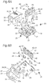
- the first embodiment of the electromagnetic relay according to the invention has a base 10, an electromagnet unit 30, a movable contact unit 40, and an insulating member 50.
- the base 10 which is a rectangular resin molded member, supports two sets of contact terminals vertically implanted at neighborhood corners thereof, each contact set having a normally closed stationary contact terminal 21 and a normally opened stationary contact terminal 22.
- Each of the normally closed stationary contact terminals 21 supports an insulating member 50 mounted thereon (which will be described below), and each of the normally opened stationary contact terminals 22 supports a normally opened stationary contact 24 fixed thereon.
- the upper surface of the base 10 has a transverse groove 13 formed between the normally closed stationary contact terminal 21 and the normally opened stationary contact terminal 22 and two longitudinal grooves 11 and 12 formed inward of and adjacent the normally closed and opened stationary contact terminals 21 and 22 and extending across the transverse groove 13.
- the base 10 also supports two coil terminals 26 vertically implanted at the remaining neighborhood corners thereof and has a pair of positioning projections 15 integrally formed therewith between and adjacent the coil terminals 26.
- the base 10 further has a threaded hole 16 formed therein between the positioning projections 15.
- a pair of movable contact terminals 25 are vertically implanted in the base 10 between the opposing normally opened stationary contact terminal 22 and the coil terminal 26.
- the base 10 furthermore has a pair of engaging projections 17 formed in opposing side surfaces thereof.
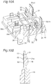
- the electromagnet unit 30 has a spool 32, a rectangular iron core 31 inserted in the spool 32 with opposite ends thereof projected to form opposite magnetic pole portions 31a and 31b, a coil 33 wound around the spool 32, and an L-shaped yoke 34 fixed on one magnetic pole portion 31b ( Fig. 1A ).
- the lower end of the yoke 34 terminates at a mounting tongue 35 having a threaded hole 35a formed therein ( Fig. 3B ).
- the upper horizontal portion of the yoke 34 has an engaging nail 36 formed therewith for supporting one end of a return spring 37.
- the electromagnet unit 30 is mounted on the base 10 with the mounting tongue 35 positioned between the positioning projections 15 and fixed on the base 10 by a screw 36a through the threaded hole 16.
- the opposite ends of the coil 33 are wound around the winding portions 26a of the coil terminals 26 and then soldered thereto.
- the movable contact unit 40 which has an insulating block 43 and a pair of movable contact plates 42 integrally molded in the insulating block 43, is fixed by using a fixing plate 44 on a movable iron plate 41 which is pivotally connected to a horizontal, distal end of the yoke 34.
- the movable iron plate 41 has a magnetic shield member 41b ( Fig. 3B ) mounted on a portion thereof which is attracted to a magnetic pole portion 31a of the iron core 31.
- the movable iron plate 41 has an engaging nail 41a extending upwardly from an upper edge thereof, with which the other end of the return spring 37 is engaged.
- the movable contact plates 42 which have movable contacts 45 fixed on the lower ends thereof, are connected to movable contact terminals 25 through lead wires 46 electrically connected to the upper ends of the movable contact plates 42.
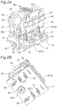
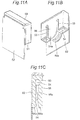
- the insulating member 50 has a resin molded insulation body 51.
- the insulation body 51 supports a metal member 52 fixedly mounted on one surface portion opposing the movable contact 45 by three fixing portions 53.
- the metal member 52 has a lower end portion 52a extending from the insulation body 51.
- the insulation body 51 has an insertion hole 54 formed therein, which is capable of mounting from above on the upper end of the normally closed stationary contact terminal 21.
- the insulation body 51 further has projections 54a and 54b mounted at the center of the opening edges of the insertion hole 54.
- the other surface portion of the insulation body 51, away from the metal member 52 has a pair of slits 55 connected to the insertion hole 54 and an elastic nail 56 formed between the slits 55.
- An inward facing surface of the elastic nail 56 has a projected, engaging nail 56a for engagement with the through-hole 21a of the normally closed stationary contact terminal 21 ( Fig. 3 ).
- the projection 54a mounted on the distal end of the elastic nail 56 is positioned so that it does not suffer damage from arcing.
- the projection 54b adjacent the metal member 52 opposes the movable contact 45 so that an impinging impact of the movable contact 45 against the metal member 52 is absorbed and then reduced.
- the positions and the number of the fixing portions 53 may be determined as necessary.
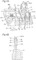
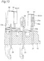
- the insulating member 50 is fitted on the upper end of the normally closed stationary contact terminal 21 from above so that the engaging nail 56a is engagingly retained the through hole 21a of the normally closed stationary contact terminal 21.
- the metal member 52 opposes the movable contact 45 so that they can make and break a contact therebetween.
- the lower end portion 52a of the metal member 52 extends toward, but not reaches, the upper surface of the base 10.
- the movable iron plate 41 is attracted to the magnetic pole portion 31a of the iron core 31, which moves the movable iron plate 41 against the spring force of the return spring 37.
- the movable contact 45 is separated from the metal member 52 of the insulating member 50 and, instead, brought into contact with the normally opened stationary contact 24 and then the magnetic shield member 41b of the movable iron plate 41 is brought into the magnetic pole portion 31a.
- the metal particles caused by the arcing may scatter and accumulate on the base, but they do not reach or accumulate on the back of the metal member 52. Namely, even if the scattering, metal particles drop and accumulate due to a number of connections and disconnections of the contacts, they are prevented from reaching the normally closed stationary contact terminal 21. Also, the normally closed stationary contact terminal 21 and the movable contact 45 are insulated from each other by the insulating member 50, no short circuit occurs between the movable contact plate 42 and the normally opened stationary contact terminal 22.
- an extended insulation surface distance is formed by the transverse grooves 13 and the longitudinal grooves 11 and 12 on the base 10, which increases the insulating property of the electromagnetic relay.
- transverse grooves 13 and the longitudinal grooves 11 and 12 may be replaced by slots, for example.
- an electronic device is similar to the first embodiment except that the insulating member 50 is mounted in a different position.
- the normally closed stationary contact 23 is fixed on the normally closed stationary contact terminal 21, and the movable contact 45 of the movable contact plate 42 is configured to make and break contact with the normally closed stationary contact 23.
- the insulating member 50 is mounted on the normally opened stationary contact terminal 22.
- the movable contact plates 42 are electrically connected through the lead wires 46. No movable contact terminal is provided in this embodiment. Because other structures of this embodiment are substantially the same as those of the first embodiment, like parts are designated by like reference numerals and the duplicate descriptions are eliminated.
- an electromagnetic relay which is available in different purposes can be obtained.
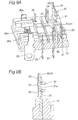
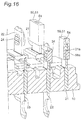
- the third embodiment of the invention has the insulating member 50 which includes the insulation body 51 and the metal member 52 fixed to the insulation body 51 at the fixing portions 53.
- the insulation body 51 has an elastic projection 57 which is configured to elastically engage the through-hole 21a of the normally closed stationary contact terminal 21 and to hold the normally closed stationary contact terminal 21.
- the insulating member 50 may be mounted on the normally opened stationary contact terminal 22. Because other structures are substantially the same as the corresponding structures of the first embodiment, like parts are designated by like reference numerals and duplicate descriptions are eliminated.
- the fourth embodiment is substantially the same as the first embodiment except that the fixing portion 58 of the insulation body 51 is fixed in the through-hole 21a of the normally closed stationary contact terminal 21. Because other structures are substantially the same as the corresponding structures of the first embodiment, like parts are designated by like reference numerals and duplicate descriptions are eliminated.
- the bent metal member 52 may be insert-molded in the insulation body 51 of the insulating member 50, which simplifies the assembling process to increase the productivity of the electromagnetic relay.
- the insulating member 50 is not limited to those described in the previous embodiments and it may be modified in various ways.
- the metal member 52 may be integrally attached on one surface of the insulation body 51; namely, the outline of the metal member 52 may be the same as that of the surface of the insulation body 51 for supporting the metal member 52 (sixth embodiment).
- the insulating member 50 may be a portion which is formed by extending the lower end portion 52a of the metal member 52 (seventh embodiment).
- the lower end portion 52a of the metal member 52 may be covered by a portion 51a which is extended from the lower end of the insulation body 51 (eighth embodiment). According to the embodiment, the lower end portion 52a of the metal member 52 is covered by the extended portion 51a of the insulation body 51, which increases an insulation surface distance and, as a result, an insulation property of the electromagnetic relay.
- the metal member may be eliminated from the insulation member and, instead, the extended portion 51a may be formed by extending the lower end of the insulation body 51.
- the lower end of the insulation body 51 may not be extended.
- the insulation body 51 is not limited to a resin molded product and it may be a ceramic product.
- the invention is not limited to the above-described electromagnetic relays and can be employed in other electromagnetic relays.
Landscapes
- Physics & Mathematics (AREA)
- Electromagnetism (AREA)
- Switch Cases, Indication, And Locking (AREA)
- Electromagnets (AREA)
Claims (9)
- Relais électromagnétique comprenant :
une base (10) :une première borne de contact fixe (22) et une seconde borne de contact fixe (21) qui sont implantées verticalement dans la base (10) ;une unité électromagnétique (30) comprenant une bobine (33) montée sur la base (10) ;une plaque de contact mobile (42) qui est supportée afin d'être mobile, de manière pivotante ; etun contact mobile (45) monté sur une extrémité distale de la plaque de contact mobile (42), dans lequel :
la première borne de contact fixe (22) a un contact fixe (24) ; caractérisé en ce que :la seconde borne de contact fixe (21) est recouverte par un élément isolant (50), l'élément isolant (50) comprend un élément métallique (52) et un corps d'isolation (51) ayant des surfaces avant et arrière opposées, et l'une des surfaces avant et arrière opposée au contact mobile (45) supporte l'élément métallique (52) monté sur ce dernier, etle contact mobile (45) est adapté pour établir le contact, de manière alternée, avec le contact fixe (24) et l'élément métallique (52) en chargeant et en déchargeant d'énergie électrique la bobine (33) de l'unité électromagnétique (30) pour déplacer la plaque de contact mobile (42) avec le contact mobile (45). - Relais électromagnétique selon la revendication 1, dans lequel une extrémité inférieure (52a) de l'élément métallique (52) s'étend vers la base (10) mais n'atteint pas la base (10).
- Relais électromagnétique selon la revendication 2, dans lequel l'extrémité inférieure (52a) de l'élément métallique (52) est recouverte avec une partie (51a) qui est étendue à partir du corps d'isolation (51).
- Relais électromagnétique selon la revendication 1, dans lequel l'élément isolant (50) a un trou d'insertion (54) ajusté, dans lequel une extrémité supérieure de la seconde borne de contact fixe (21) est mise en prise.
- Relais électromagnétique selon la revendication 4, dans lequel un clou de mise en prise (56a) est prévu sur et fait saillie d'une surface interne du trou d'insertion (54) de l'élément isolant (50) afin de se mettre en prise dans un trou débouchant (21a) de la seconde borne de contact fixe (21).
- Relais électromagnétique selon la revendication 5, dans lequel l'élément isolant (50) a des fentes (55) prévues sur les côtés opposés du clou de mise en prise (56a) et un clou élastique (56) formé entre les fentes.
- Relais électromagnétique selon la revendication 1, dans lequel l'élément isolant (50) a une saillie élastique (57) qui se met en prise dans un trou débouchant de la seconde borne de contact fixe (21) .
- Relais électromagnétique selon la revendication 1, dans lequel l'élément isolant (50) a une partie de fixation (53) en saillie à partir de ce dernier, la partie de fixation étant fixée dans un trou débouchant de la seconde borne de contact fixe (21).
- Relais électromagnétique selon la revendication 1, dans lequel l'élément isolant (50) a une partie qui s'étend à partir de son extrémité inférieure vers la base (10), mais n'atteint pas la base (10), la partie étendue (51a) étant configurée pour s'opposer et recouvrir une surface de la seconde borne de contact fixe (21).
Applications Claiming Priority (1)
| Application Number | Priority Date | Filing Date | Title |
|---|---|---|---|
| JP2014052072A JP6277795B2 (ja) | 2014-03-14 | 2014-03-14 | 電磁継電器 |
Publications (2)
| Publication Number | Publication Date |
|---|---|
| EP2919252A1 EP2919252A1 (fr) | 2015-09-16 |
| EP2919252B1 true EP2919252B1 (fr) | 2018-05-09 |
Family
ID=52596875
Family Applications (1)
| Application Number | Title | Priority Date | Filing Date |
|---|---|---|---|
| EP15157864.8A Not-in-force EP2919252B1 (fr) | 2014-03-14 | 2015-03-05 | Relais électromagnétique |
Country Status (4)
| Country | Link |
|---|---|
| US (1) | US20150262764A1 (fr) |
| EP (1) | EP2919252B1 (fr) |
| JP (1) | JP6277795B2 (fr) |
| CN (1) | CN104916499B (fr) |
Cited By (1)
| Publication number | Priority date | Publication date | Assignee | Title |
|---|---|---|---|---|
| TWI680483B (zh) * | 2019-07-03 | 2019-12-21 | 百容電子股份有限公司 | 電磁繼電器 |
Families Citing this family (7)
| Publication number | Priority date | Publication date | Assignee | Title |
|---|---|---|---|---|
| JP6132043B1 (ja) | 2016-02-23 | 2017-05-24 | オムロン株式会社 | 電力開閉装置 |
| JP6806007B2 (ja) * | 2017-08-31 | 2020-12-23 | オムロン株式会社 | 電磁継電器 |
| JP7029284B2 (ja) * | 2017-12-12 | 2022-03-03 | パナソニックIpマネジメント株式会社 | 接点装置及び電磁継電器 |
| CN108231441B (zh) * | 2018-03-12 | 2024-02-20 | 西安开天铁路电气股份有限公司 | 一种触头结构 |
| JP6973200B2 (ja) * | 2018-03-13 | 2021-11-24 | オムロン株式会社 | 接点開閉装置 |
| TWI692793B (zh) * | 2019-01-19 | 2020-05-01 | 百容電子股份有限公司 | 電磁繼電器 |
| CN110047707B (zh) * | 2019-04-30 | 2024-07-30 | 厦门宏发密封继电器有限公司 | 一种立方英寸两组转换触点继电器的压簧片和密封继电器 |
Family Cites Families (10)
| Publication number | Priority date | Publication date | Assignee | Title |
|---|---|---|---|---|
| US2247469A (en) * | 1935-03-21 | 1941-07-01 | Utah Radio Products Company | Vibratory motor |
| JPS56141348U (fr) * | 1980-03-25 | 1981-10-26 | ||
| EP0189921B1 (fr) * | 1985-01-31 | 1989-08-02 | Nec Corporation | Relais électromagnétique |
| AU572732B2 (en) * | 1985-06-20 | 1988-05-12 | Honda Giken Kogyo Kabushiki Kaisha | Battery mounted electromagnetic switch |
| DE3823315A1 (de) * | 1988-07-09 | 1990-01-11 | Zettler Elektrotechn Alois | Isolierkoerper zwischen den spannungsfuehrenden kontakten eines kontaktfedersatzes fuer elektromagnetische relais |
| WO2000041202A1 (fr) * | 1998-12-28 | 2000-07-13 | Mitsubishi Denki Kabushiki Kaisha | Limiteur de courant et disjoncteur avec limitation de courant |
| JP2006331782A (ja) * | 2005-05-25 | 2006-12-07 | Nec Tokin Corp | 電磁リレー |
| CN201490104U (zh) * | 2009-08-24 | 2010-05-26 | 刘方云 | 一种继电器的轭铁组件的结构装置 |
| US8383975B2 (en) * | 2011-01-28 | 2013-02-26 | Zippy Technology Corp. | Enhanced withstand voltage micro switch |
| CN203882895U (zh) * | 2014-06-05 | 2014-10-15 | 温州西卡电器有限公司 | 空调接触器 |
-
2014
- 2014-03-14 JP JP2014052072A patent/JP6277795B2/ja not_active Expired - Fee Related
-
2015
- 2015-02-27 CN CN201510092023.4A patent/CN104916499B/zh not_active Expired - Fee Related
- 2015-03-05 EP EP15157864.8A patent/EP2919252B1/fr not_active Not-in-force
- 2015-03-10 US US14/643,972 patent/US20150262764A1/en not_active Abandoned
Non-Patent Citations (1)
| Title |
|---|
| None * |
Cited By (1)
| Publication number | Priority date | Publication date | Assignee | Title |
|---|---|---|---|---|
| TWI680483B (zh) * | 2019-07-03 | 2019-12-21 | 百容電子股份有限公司 | 電磁繼電器 |
Also Published As
| Publication number | Publication date |
|---|---|
| CN104916499A (zh) | 2015-09-16 |
| JP2015176743A (ja) | 2015-10-05 |
| US20150262764A1 (en) | 2015-09-17 |
| EP2919252A1 (fr) | 2015-09-16 |
| JP6277795B2 (ja) | 2018-02-14 |
| CN104916499B (zh) | 2018-06-05 |
Similar Documents
| Publication | Publication Date | Title |
|---|---|---|
| EP2919252B1 (fr) | Relais électromagnétique | |
| EP2533262B1 (fr) | Relais électromagnétique et son procédé de fabrication | |
| US8305166B2 (en) | Electromagnetic relay | |
| KR101458440B1 (ko) | 접점개폐기구 및 전자계전기 | |
| US8704621B2 (en) | Electromagnetic relay | |
| EP2840585B1 (fr) | Dispositif d'électro-aimant et relais électromagnétique l'utilisant | |
| CN103377855B (zh) | 电磁继电器 | |
| JP6277794B2 (ja) | 電磁継電器 | |
| CN103311022A (zh) | 密封接触装置 | |
| JP7613172B2 (ja) | 電磁継電器 | |
| JP5720729B2 (ja) | 接点機構部 | |
| JP5427492B2 (ja) | 電磁継電器 | |
| CN112582218A (zh) | 继电器 | |
| EP1772884A2 (fr) | Relais électromagnétique | |
| US9941773B2 (en) | Actuator with electric motor and EMI reduction circuit | |
| US10204756B2 (en) | Coil terminal and electromagnetic relay provided therewith | |
| JP4363462B2 (ja) | 高周波リレー | |
| JP5546932B2 (ja) | 電磁継電器 | |
| WO2020110912A1 (fr) | Dispositif de contact | |
| JP2021125382A (ja) | 接点装置 |
Legal Events
| Date | Code | Title | Description |
|---|---|---|---|
| PUAI | Public reference made under article 153(3) epc to a published international application that has entered the european phase |
Free format text: ORIGINAL CODE: 0009012 |
|
| 17P | Request for examination filed |
Effective date: 20150405 |
|
| AK | Designated contracting states |
Kind code of ref document: A1 Designated state(s): AL AT BE BG CH CY CZ DE DK EE ES FI FR GB GR HR HU IE IS IT LI LT LU LV MC MK MT NL NO PL PT RO RS SE SI SK SM TR |
|
| AX | Request for extension of the european patent |
Extension state: BA ME |
|
| 17Q | First examination report despatched |
Effective date: 20160729 |
|
| STAA | Information on the status of an ep patent application or granted ep patent |
Free format text: STATUS: EXAMINATION IS IN PROGRESS |
|
| RIC1 | Information provided on ipc code assigned before grant |
Ipc: H01H 50/14 20060101AFI20170320BHEP Ipc: H01H 50/54 20060101ALI20170320BHEP Ipc: H01H 50/02 20060101ALN20170320BHEP |
|
| GRAP | Despatch of communication of intention to grant a patent |
Free format text: ORIGINAL CODE: EPIDOSNIGR1 |
|
| STAA | Information on the status of an ep patent application or granted ep patent |
Free format text: STATUS: GRANT OF PATENT IS INTENDED |
|
| INTG | Intention to grant announced |
Effective date: 20170508 |
|
| GRAJ | Information related to disapproval of communication of intention to grant by the applicant or resumption of examination proceedings by the epo deleted |
Free format text: ORIGINAL CODE: EPIDOSDIGR1 |
|
| STAA | Information on the status of an ep patent application or granted ep patent |
Free format text: STATUS: EXAMINATION IS IN PROGRESS |
|
| GRAP | Despatch of communication of intention to grant a patent |
Free format text: ORIGINAL CODE: EPIDOSNIGR1 |
|
| STAA | Information on the status of an ep patent application or granted ep patent |
Free format text: STATUS: GRANT OF PATENT IS INTENDED |
|
| INTC | Intention to grant announced (deleted) | ||
| RIC1 | Information provided on ipc code assigned before grant |
Ipc: H01H 50/02 20060101ALN20171016BHEP Ipc: H01H 50/14 20060101AFI20171016BHEP Ipc: H01H 50/54 20060101ALI20171016BHEP |
|
| INTG | Intention to grant announced |
Effective date: 20171031 |
|
| GRAS | Grant fee paid |
Free format text: ORIGINAL CODE: EPIDOSNIGR3 |
|
| GRAA | (expected) grant |
Free format text: ORIGINAL CODE: 0009210 |
|
| STAA | Information on the status of an ep patent application or granted ep patent |
Free format text: STATUS: THE PATENT HAS BEEN GRANTED |
|
| AK | Designated contracting states |
Kind code of ref document: B1 Designated state(s): AL AT BE BG CH CY CZ DE DK EE ES FI FR GB GR HR HU IE IS IT LI LT LU LV MC MK MT NL NO PL PT RO RS SE SI SK SM TR |
|
| REG | Reference to a national code |
Ref country code: GB Ref legal event code: FG4D |
|
| REG | Reference to a national code |
Ref country code: CH Ref legal event code: EP Ref country code: AT Ref legal event code: REF Ref document number: 998282 Country of ref document: AT Kind code of ref document: T Effective date: 20180515 |
|
| REG | Reference to a national code |
Ref country code: IE Ref legal event code: FG4D |
|
| REG | Reference to a national code |
Ref country code: DE Ref legal event code: R096 Ref document number: 602015010841 Country of ref document: DE |
|
| REG | Reference to a national code |
Ref country code: NL Ref legal event code: MP Effective date: 20180509 |
|
| REG | Reference to a national code |
Ref country code: LT Ref legal event code: MG4D |
|
| PG25 | Lapsed in a contracting state [announced via postgrant information from national office to epo] |
Ref country code: NO Free format text: LAPSE BECAUSE OF FAILURE TO SUBMIT A TRANSLATION OF THE DESCRIPTION OR TO PAY THE FEE WITHIN THE PRESCRIBED TIME-LIMIT Effective date: 20180809 Ref country code: FI Free format text: LAPSE BECAUSE OF FAILURE TO SUBMIT A TRANSLATION OF THE DESCRIPTION OR TO PAY THE FEE WITHIN THE PRESCRIBED TIME-LIMIT Effective date: 20180509 Ref country code: BG Free format text: LAPSE BECAUSE OF FAILURE TO SUBMIT A TRANSLATION OF THE DESCRIPTION OR TO PAY THE FEE WITHIN THE PRESCRIBED TIME-LIMIT Effective date: 20180809 Ref country code: SE Free format text: LAPSE BECAUSE OF FAILURE TO SUBMIT A TRANSLATION OF THE DESCRIPTION OR TO PAY THE FEE WITHIN THE PRESCRIBED TIME-LIMIT Effective date: 20180509 Ref country code: LT Free format text: LAPSE BECAUSE OF FAILURE TO SUBMIT A TRANSLATION OF THE DESCRIPTION OR TO PAY THE FEE WITHIN THE PRESCRIBED TIME-LIMIT Effective date: 20180509 Ref country code: ES Free format text: LAPSE BECAUSE OF FAILURE TO SUBMIT A TRANSLATION OF THE DESCRIPTION OR TO PAY THE FEE WITHIN THE PRESCRIBED TIME-LIMIT Effective date: 20180509 |
|
| PG25 | Lapsed in a contracting state [announced via postgrant information from national office to epo] |
Ref country code: NL Free format text: LAPSE BECAUSE OF FAILURE TO SUBMIT A TRANSLATION OF THE DESCRIPTION OR TO PAY THE FEE WITHIN THE PRESCRIBED TIME-LIMIT Effective date: 20180509 Ref country code: HR Free format text: LAPSE BECAUSE OF FAILURE TO SUBMIT A TRANSLATION OF THE DESCRIPTION OR TO PAY THE FEE WITHIN THE PRESCRIBED TIME-LIMIT Effective date: 20180509 Ref country code: RS Free format text: LAPSE BECAUSE OF FAILURE TO SUBMIT A TRANSLATION OF THE DESCRIPTION OR TO PAY THE FEE WITHIN THE PRESCRIBED TIME-LIMIT Effective date: 20180509 Ref country code: LV Free format text: LAPSE BECAUSE OF FAILURE TO SUBMIT A TRANSLATION OF THE DESCRIPTION OR TO PAY THE FEE WITHIN THE PRESCRIBED TIME-LIMIT Effective date: 20180509 Ref country code: GR Free format text: LAPSE BECAUSE OF FAILURE TO SUBMIT A TRANSLATION OF THE DESCRIPTION OR TO PAY THE FEE WITHIN THE PRESCRIBED TIME-LIMIT Effective date: 20180810 |
|
| REG | Reference to a national code |
Ref country code: AT Ref legal event code: MK05 Ref document number: 998282 Country of ref document: AT Kind code of ref document: T Effective date: 20180509 |
|
| PG25 | Lapsed in a contracting state [announced via postgrant information from national office to epo] |
Ref country code: PL Free format text: LAPSE BECAUSE OF FAILURE TO SUBMIT A TRANSLATION OF THE DESCRIPTION OR TO PAY THE FEE WITHIN THE PRESCRIBED TIME-LIMIT Effective date: 20180509 Ref country code: EE Free format text: LAPSE BECAUSE OF FAILURE TO SUBMIT A TRANSLATION OF THE DESCRIPTION OR TO PAY THE FEE WITHIN THE PRESCRIBED TIME-LIMIT Effective date: 20180509 Ref country code: AT Free format text: LAPSE BECAUSE OF FAILURE TO SUBMIT A TRANSLATION OF THE DESCRIPTION OR TO PAY THE FEE WITHIN THE PRESCRIBED TIME-LIMIT Effective date: 20180509 Ref country code: CZ Free format text: LAPSE BECAUSE OF FAILURE TO SUBMIT A TRANSLATION OF THE DESCRIPTION OR TO PAY THE FEE WITHIN THE PRESCRIBED TIME-LIMIT Effective date: 20180509 Ref country code: RO Free format text: LAPSE BECAUSE OF FAILURE TO SUBMIT A TRANSLATION OF THE DESCRIPTION OR TO PAY THE FEE WITHIN THE PRESCRIBED TIME-LIMIT Effective date: 20180509 Ref country code: DK Free format text: LAPSE BECAUSE OF FAILURE TO SUBMIT A TRANSLATION OF THE DESCRIPTION OR TO PAY THE FEE WITHIN THE PRESCRIBED TIME-LIMIT Effective date: 20180509 Ref country code: SK Free format text: LAPSE BECAUSE OF FAILURE TO SUBMIT A TRANSLATION OF THE DESCRIPTION OR TO PAY THE FEE WITHIN THE PRESCRIBED TIME-LIMIT Effective date: 20180509 |
|
| REG | Reference to a national code |
Ref country code: DE Ref legal event code: R097 Ref document number: 602015010841 Country of ref document: DE |
|
| PG25 | Lapsed in a contracting state [announced via postgrant information from national office to epo] |
Ref country code: SM Free format text: LAPSE BECAUSE OF FAILURE TO SUBMIT A TRANSLATION OF THE DESCRIPTION OR TO PAY THE FEE WITHIN THE PRESCRIBED TIME-LIMIT Effective date: 20180509 Ref country code: IT Free format text: LAPSE BECAUSE OF FAILURE TO SUBMIT A TRANSLATION OF THE DESCRIPTION OR TO PAY THE FEE WITHIN THE PRESCRIBED TIME-LIMIT Effective date: 20180509 |
|
| PLBE | No opposition filed within time limit |
Free format text: ORIGINAL CODE: 0009261 |
|
| STAA | Information on the status of an ep patent application or granted ep patent |
Free format text: STATUS: NO OPPOSITION FILED WITHIN TIME LIMIT |
|
| 26N | No opposition filed |
Effective date: 20190212 |
|
| PG25 | Lapsed in a contracting state [announced via postgrant information from national office to epo] |
Ref country code: SI Free format text: LAPSE BECAUSE OF FAILURE TO SUBMIT A TRANSLATION OF THE DESCRIPTION OR TO PAY THE FEE WITHIN THE PRESCRIBED TIME-LIMIT Effective date: 20180509 |
|
| PG25 | Lapsed in a contracting state [announced via postgrant information from national office to epo] |
Ref country code: MC Free format text: LAPSE BECAUSE OF FAILURE TO SUBMIT A TRANSLATION OF THE DESCRIPTION OR TO PAY THE FEE WITHIN THE PRESCRIBED TIME-LIMIT Effective date: 20180509 |
|
| REG | Reference to a national code |
Ref country code: CH Ref legal event code: PL |
|
| GBPC | Gb: european patent ceased through non-payment of renewal fee |
Effective date: 20190305 |
|
| PG25 | Lapsed in a contracting state [announced via postgrant information from national office to epo] |
Ref country code: AL Free format text: LAPSE BECAUSE OF FAILURE TO SUBMIT A TRANSLATION OF THE DESCRIPTION OR TO PAY THE FEE WITHIN THE PRESCRIBED TIME-LIMIT Effective date: 20180509 Ref country code: LU Free format text: LAPSE BECAUSE OF NON-PAYMENT OF DUE FEES Effective date: 20190305 |
|
| REG | Reference to a national code |
Ref country code: BE Ref legal event code: MM Effective date: 20190331 |
|
| PG25 | Lapsed in a contracting state [announced via postgrant information from national office to epo] |
Ref country code: LI Free format text: LAPSE BECAUSE OF NON-PAYMENT OF DUE FEES Effective date: 20190331 Ref country code: GB Free format text: LAPSE BECAUSE OF NON-PAYMENT OF DUE FEES Effective date: 20190305 Ref country code: CH Free format text: LAPSE BECAUSE OF NON-PAYMENT OF DUE FEES Effective date: 20190331 Ref country code: IE Free format text: LAPSE BECAUSE OF NON-PAYMENT OF DUE FEES Effective date: 20190305 |
|
| PG25 | Lapsed in a contracting state [announced via postgrant information from national office to epo] |
Ref country code: FR Free format text: LAPSE BECAUSE OF NON-PAYMENT OF DUE FEES Effective date: 20190331 Ref country code: BE Free format text: LAPSE BECAUSE OF NON-PAYMENT OF DUE FEES Effective date: 20190331 |
|
| PG25 | Lapsed in a contracting state [announced via postgrant information from national office to epo] |
Ref country code: TR Free format text: LAPSE BECAUSE OF FAILURE TO SUBMIT A TRANSLATION OF THE DESCRIPTION OR TO PAY THE FEE WITHIN THE PRESCRIBED TIME-LIMIT Effective date: 20180509 |
|
| PG25 | Lapsed in a contracting state [announced via postgrant information from national office to epo] |
Ref country code: PT Free format text: LAPSE BECAUSE OF FAILURE TO SUBMIT A TRANSLATION OF THE DESCRIPTION OR TO PAY THE FEE WITHIN THE PRESCRIBED TIME-LIMIT Effective date: 20180910 Ref country code: MT Free format text: LAPSE BECAUSE OF NON-PAYMENT OF DUE FEES Effective date: 20190305 |
|
| PG25 | Lapsed in a contracting state [announced via postgrant information from national office to epo] |
Ref country code: CY Free format text: LAPSE BECAUSE OF FAILURE TO SUBMIT A TRANSLATION OF THE DESCRIPTION OR TO PAY THE FEE WITHIN THE PRESCRIBED TIME-LIMIT Effective date: 20180509 |
|
| PG25 | Lapsed in a contracting state [announced via postgrant information from national office to epo] |
Ref country code: IS Free format text: LAPSE BECAUSE OF FAILURE TO SUBMIT A TRANSLATION OF THE DESCRIPTION OR TO PAY THE FEE WITHIN THE PRESCRIBED TIME-LIMIT Effective date: 20180909 |
|
| PG25 | Lapsed in a contracting state [announced via postgrant information from national office to epo] |
Ref country code: HU Free format text: LAPSE BECAUSE OF FAILURE TO SUBMIT A TRANSLATION OF THE DESCRIPTION OR TO PAY THE FEE WITHIN THE PRESCRIBED TIME-LIMIT; INVALID AB INITIO Effective date: 20150305 |
|
| PG25 | Lapsed in a contracting state [announced via postgrant information from national office to epo] |
Ref country code: MK Free format text: LAPSE BECAUSE OF FAILURE TO SUBMIT A TRANSLATION OF THE DESCRIPTION OR TO PAY THE FEE WITHIN THE PRESCRIBED TIME-LIMIT Effective date: 20180509 |
|
| PGFP | Annual fee paid to national office [announced via postgrant information from national office to epo] |
Ref country code: DE Payment date: 20230131 Year of fee payment: 9 |
|
| REG | Reference to a national code |
Ref country code: DE Ref legal event code: R119 Ref document number: 602015010841 Country of ref document: DE |
|
| PG25 | Lapsed in a contracting state [announced via postgrant information from national office to epo] |
Ref country code: DE Free format text: LAPSE BECAUSE OF NON-PAYMENT OF DUE FEES Effective date: 20241001 |
|
| PG25 | Lapsed in a contracting state [announced via postgrant information from national office to epo] |
Ref country code: DE Free format text: LAPSE BECAUSE OF NON-PAYMENT OF DUE FEES Effective date: 20241001 |