EP2919318B1 - Basisstationsantennenspeisenetzwerk - Google Patents
Basisstationsantennenspeisenetzwerk Download PDFInfo
- Publication number
- EP2919318B1 EP2919318B1 EP13898577.5A EP13898577A EP2919318B1 EP 2919318 B1 EP2919318 B1 EP 2919318B1 EP 13898577 A EP13898577 A EP 13898577A EP 2919318 B1 EP2919318 B1 EP 2919318B1
- Authority
- EP
- European Patent Office
- Prior art keywords
- phase shifter
- feeding network
- phase
- feeding
- transmission line
- Prior art date
- Legal status (The legal status is an assumption and is not a legal conclusion. Google has not performed a legal analysis and makes no representation as to the accuracy of the status listed.)
- Not-in-force
Links
- 239000002184 metal Substances 0.000 claims description 23
- 230000005540 biological transmission Effects 0.000 claims description 14
- 230000009977 dual effect Effects 0.000 claims description 12
- 238000010030 laminating Methods 0.000 claims description 3
- 238000009413 insulation Methods 0.000 claims description 2
- 238000010586 diagram Methods 0.000 description 14
- 239000010410 layer Substances 0.000 description 14
- 238000005516 engineering process Methods 0.000 description 10
- 239000004020 conductor Substances 0.000 description 9
- 230000007812 deficiency Effects 0.000 description 5
- 238000003466 welding Methods 0.000 description 4
- 230000000712 assembly Effects 0.000 description 3
- 238000000429 assembly Methods 0.000 description 3
- 238000004519 manufacturing process Methods 0.000 description 3
- 230000008878 coupling Effects 0.000 description 2
- 238000010168 coupling process Methods 0.000 description 2
- 238000005859 coupling reaction Methods 0.000 description 2
- 239000002355 dual-layer Substances 0.000 description 2
- 238000010295 mobile communication Methods 0.000 description 2
- 239000002356 single layer Substances 0.000 description 2
- 150000001875 compounds Chemical class 0.000 description 1
- 230000010363 phase shift Effects 0.000 description 1
- 230000008844 regulatory mechanism Effects 0.000 description 1
Images


Classifications
-
- H—ELECTRICITY
- H01—ELECTRIC ELEMENTS
- H01Q—ANTENNAS, i.e. RADIO AERIALS
- H01Q21/00—Antenna arrays or systems
- H01Q21/0006—Particular feeding systems
- H01Q21/0075—Stripline fed arrays
-
- H—ELECTRICITY
- H01—ELECTRIC ELEMENTS
- H01P—WAVEGUIDES; RESONATORS, LINES, OR OTHER DEVICES OF THE WAVEGUIDE TYPE
- H01P1/00—Auxiliary devices
- H01P1/18—Phase-shifters
- H01P1/182—Waveguide phase-shifters
-
- H—ELECTRICITY
- H01—ELECTRIC ELEMENTS
- H01P—WAVEGUIDES; RESONATORS, LINES, OR OTHER DEVICES OF THE WAVEGUIDE TYPE
- H01P1/00—Auxiliary devices
- H01P1/18—Phase-shifters
- H01P1/183—Coaxial phase-shifters
-
- H—ELECTRICITY
- H01—ELECTRIC ELEMENTS
- H01P—WAVEGUIDES; RESONATORS, LINES, OR OTHER DEVICES OF THE WAVEGUIDE TYPE
- H01P1/00—Auxiliary devices
- H01P1/18—Phase-shifters
- H01P1/184—Strip line phase-shifters
-
- H—ELECTRICITY
- H01—ELECTRIC ELEMENTS
- H01P—WAVEGUIDES; RESONATORS, LINES, OR OTHER DEVICES OF THE WAVEGUIDE TYPE
- H01P3/00—Waveguides; Transmission lines of the waveguide type
- H01P3/02—Waveguides; Transmission lines of the waveguide type with two longitudinal conductors
- H01P3/08—Microstrips; Strip lines
- H01P3/081—Microstriplines
- H01P3/084—Suspended microstriplines
-
- H—ELECTRICITY
- H01—ELECTRIC ELEMENTS
- H01P—WAVEGUIDES; RESONATORS, LINES, OR OTHER DEVICES OF THE WAVEGUIDE TYPE
- H01P5/00—Coupling devices of the waveguide type
- H01P5/12—Coupling devices having more than two ports
-
- H—ELECTRICITY
- H01—ELECTRIC ELEMENTS
- H01Q—ANTENNAS, i.e. RADIO AERIALS
- H01Q3/00—Arrangements for changing or varying the orientation or the shape of the directional pattern of the waves radiated from an antenna or antenna system
- H01Q3/26—Arrangements for changing or varying the orientation or the shape of the directional pattern of the waves radiated from an antenna or antenna system varying the relative phase or relative amplitude of energisation between two or more active radiating elements; varying the distribution of energy across a radiating aperture
- H01Q3/30—Arrangements for changing or varying the orientation or the shape of the directional pattern of the waves radiated from an antenna or antenna system varying the relative phase or relative amplitude of energisation between two or more active radiating elements; varying the distribution of energy across a radiating aperture varying the relative phase between the radiating elements of an array
- H01Q3/32—Arrangements for changing or varying the orientation or the shape of the directional pattern of the waves radiated from an antenna or antenna system varying the relative phase or relative amplitude of energisation between two or more active radiating elements; varying the distribution of energy across a radiating aperture varying the relative phase between the radiating elements of an array by mechanical means
Definitions
- This disclosure generally relates to mobile communication technologies and, more particularly, to a feeding network used for electrically adjustable base station antenna.
- phase shifting device for a phase shifting device in the traditional technology, the back-and-forth movement of a metal conductor rod in a metal conductor tube is used to change the actual length of a transmission path to achieve the purpose of phase change.
- power dividers must be added for power division.
- the volume of the phase shifter normally needs to be increased, resulting in a complicated structure of the feeding network and poor electrical performance and consistence of the product.
- micro-strip type power dividers and phase shifters are used for an equal-phase difference multi-path compound phase shifter in existing technologies. Deficiencies such as high loss and unstable performance are present, especially for the length regulation mechanism of the phase shifter. So they have limited usage in mass production.
- CN 102157767 relates to a coaxial medium phase shifter.
- the phase shifter comprises an inner conductor and an outer conductor, wherein the inner conductor defines at least two parallel conduction arms and the outer conductor provides coaxial cavities for the conduction arms. Medium elements move along the axial direction of the coaxial cavities to change the phase of signals.
- CN 102157767 also describes an antenna array with five radiating elements, four separate coaxial medium phase shifters, a 3-way power splitter and two 2-way power splitters.
- CN 101707271 relates to an equiphase differential multiplexed phase shifter comprising a plurality of phase shifter subunits, a plurality of power divider subunits, a metallic reflector plate, a sliding device and a positioning device for limiting the sliding stroke.
- the phase shifter subunits are serially connected with a main circuit of the power divider subunits, and consist of fixed transmission lines and slidable transmission lines.
- This invention intends to provide with a feeding network for base station antenna with compact structure, flexible design of power division ratio, and stable performance.
- This invention cascades the various power dividers and phase shifters in a distributed way, achieving flexible design of power division ratio, stable performance, and relatively low power loss. It further optimizes the phase shifters and power dividers as well as the general structure of the feeding network, achieving compact structure of the feeding network, relatively small dimensions, ease for processing, and reduced cost.
- the wide band can be achieved easily, and the general performance and consistency are more stable. They can also be combined flexibly to increase the number of output terminals, resolving the demand for wide-band feeding network for electrically adjustable base station antenna.
- the phase shifters are based on the nest coupling principle of metal tube and can achieve excellent consistency, flexible design of power division ratio, stable performance, and relatively low power loss.
- the various functional components are assembled in a narrow and long metal cavity that is integrally formed.
- the various feeding ports are distributed along its long side.
- the functional assemblies are also set inside the cavity, overcoming the deficiencies such as complicated structure, too many welding spots, and high power loss in existing technologies. It can achieve a compact structure of the feeding network, relatively small dimensions, ease for processing, and reduced cost.
- the wide band can be achieved easily, and the general performance and consistency are more stable. Compared with other structures, it can avoid signal leakage effectively and avoid resonance points.
- the section of this metal cavity structure can be a single rectangle, a one-side-opened single rectangle, an up-down dual rectangle, an up-down one-side-opened dual rectangle, a left-right dual rectangle, a left-right one-side-opened dual rectangle, or a multi-cavity structure formed by combing two or more of the above. They can also be combined flexibly to increase the number of output terminals, resolving the demand for wide-band feeding network for electrically adjustable base station antenna.
- the power divider is composed of an air strip line in a branch form.
- the strip line is of flat, round, square or other shape, or a combination thereof.
- the single-row feeding structure is combined through a tiling and/or laminating form and can constitute a phase-shifting feeding network with more output terminals.
- the various phase shifters are identical and can achieve equidifferent phase change.
- This invention provides with a feeding network for base station antenna, which is characterized by compact structure, stable performance, flexible combination, and extremely low loss.
- This invention cascades various power dividers and phase shifters in a distributed way.
- the phase shifters are based on the nest coupling principle of metal tube, achieving excellent consistency, flexible design of power division ratio, stable performance, and relatively low power loss. It further optimizes the phase shifters and power dividers as well as the general structure of the feeding network.
- the various functional components are assembled in a narrow and long metal cavity, which is integrally formed. A plurality of feeding ports are distributed along its long side.
- the functional assemblies are also set inside the cavity, overcoming the deficiencies such as complicated structure, too many welding spots, and high power loss in existing technologies. It can achieve compact structure of the feeding network, relatively small dimensions, ease for processing, and reduced cost. Wide band can be achieved easily, and the general performance and consistency are more stable. Compared with other structures, it can avoid signal leakage effectively and avoid resonance points.
- the structures can also be combined flexibly to increase the number of output terminals, resolving the demand for wide-band feeding network for electrically adjustable base station antenna.
- the feeding network for base station antenna of this invention includes a 3-way power divider.
- the power of the feeding port input is divided equally into 3 routes through this 3-way power divider. Among them, one route is used to feed the central unit of an array, and the other two output terminals are connected with the phase shifters on the left and right sides.
- the adjacent phase shifters are cascaded through a 2-way power divider and feed the units on the left and right sides of the array, respectively.
- N phase shifters and N-1 2-way power dividers as well as N' phase shifters and N'-1 2-way power dividers are provided, respectively.
- the output terminal of the previous phase shifter is connected with the input terminal of the power divider.
- One output terminal of the power divider is used as an output terminal of the whole feeding network, and the other output terminal is connected with the input terminal of the next phase shifter.
- the power division ratio can also be set as required.
- the various phase shifters are identical except that the phase shifts of the corresponding output ports on the left and right sides are in opposite directions when the sliding rod moves along the line to form a stepped phase distribution and to control the declination of the direction diagram in the vertical plane.
- the various phase shifters are identical to achieve equidifferent phase change.
- the phase shifters and the power dividers are both placed in an integrally formed metal cavity structure.
- the various feeding points are distributed evenly along the long side of the structure.
- the various functional components are assembled in a narrow and long metal cavity, which is integrally formed.
- the various feeding ports are distributed along its long side.
- the functional assemblies are also set inside the cavity, overcoming the deficiencies such as complicated structure, too many welding spots, and high power loss in existing technologies. It can achieve compact structure of the feeding network, relatively small dimensions, ease for processing, and reduced cost. The wide band can be achieved easily, and the general performance and consistency are more stable.
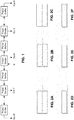
- the section of this metal cavity structure is a single rectangle (as shown in Figure 2d ), one-side-opened single rectangle (as shown in Figure 2e ), up-down dual rectangle (as shown in Figure 2a ), up-down one-side-opened dual rectangle, left-right dual rectangle, left-right one-side-opened dual rectangle, or multi-cavity structure formed by combing two or more of the above.
- the power divider is an air strip line type composed in a branch form. This strip line is of flat, round, square, or other shape, or a combination of them.
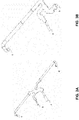
- Figures 3a ⁇ 3b are structural diagrams of the central conduction bands of the power divider of the air strip line type. In Figures 3a and 3b , a is an input terminal, and b, c, & d are output terminals.
- Figure 3a is a 3-way power divider and Figure 3b is a 2-way power divider.
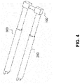
- Figure 4 is a structural diagram of the phase shifter of a deformed strip line type.
- 200 and 300 are hollow round metal tubes of fixed transmission lines.
- the moveable U-shaped metal rod 100 which is coated with an insulation medium layer on the surface, is a sliding transmission line. It is inserted into the hollow metal tubes 2 and 3, and changes the actual length of the transmission line through the moveable U-shaped metal rod 100 to adjust the phase.
- the single-row feeding structure is combined through a tiling and/or laminating form to constitute a phase-shifting feeding network with more output terminals.
- FIG. 5 is a laminated 2-in-8-out feeding network of Embodiment 1 of this invention.
- Each layer includes 7 power dividers and 8 phase shifters, constituting 1-in-9-out feeding electronic system.
- 2-1 is an input power divider and power divider 2-2 connects phase shifters 3-1 and 3-2. They are both assembled in a metal cavity 1.
- coaxial cables are used to input the signal from terminal 4-a to the input terminal 2-1-a of power divider 2-1. It is divided into three routes, i.e., 2-1-b, 2-1-c, and 2-1-d.
- the 2-1-b route connects coaxial cable 4-c and is used as an output terminal.
- 2-1-c is connected to the input terminal 3-2-a of phase shifter 3-2. After phase shifting, it is connected through its output 3-2-b to the input terminal 2-2-a of power divider 2-2. It is divided into two routes. Its output 2-2-b route connects to coaxial cable 4-e as an output of the feeding network. The 2-2-c route is connected to the input terminal 3-1-a of phase shifter 3-1. After phase shifting, it is connected through its output terminal 3-1-b to the coaxial cable 4-g as an output.
- the principle is similar to the above description. In this way, when the phase shifting device moves, the various output terminals of the upper or lower layer can obtain a phase distribution with equidifferent phase change.
- FIG. 6 is a two-layer 2-in-10-out feeding network of Embodiment 2 of this invention.
- Each layer includes 3 power dividers and 4 phase shifters, constituting 1-input-5-output feeding electronic system.
- 2-1 is an input 3-way power divider and 2-2 is a 2-way power divider.
- This 2-way power divider 2-2 connects to phase shifter 3-1 and 3-2.
- the signal is input from a coaxial input terminal 4-f.
- power divider 2-1 it is divided into 3 routes, i.e., 2-1-b, 2-1-c, and 2-1-d.
- the 2-1-b route connects to the conductor inside the coaxial wire, forming an output terminal 4-h.
- the 2-1-c route is connected to the input terminal 3-1-a of the other phase shifter. After phase shifting, output terminal 3-1-b is connected to an input terminal 2-2-a of power divider 2-2. It is divided into 2 routes.
- the 2-2-b route connects to the conductor inside the coaxial wire, forming output terminal 4-j.
- the 2-2-c route is connected to the input terminal 3-2-a of the other phase shifter. After phase shifting, its output 3-2-b is connected to the conductor inside the coaxial wire, forming output terminal 4-1.
- the feeding electronic network structure and principle are similar to the above description.
- Figure 7 is a tiling 2-in-10-out feeding network of Embodiment 3 of this invention. Its working principle is the same as the layered structure of the embodiment shown in Figure 5 except that the arrangement of the two groups of sub-networks is different.
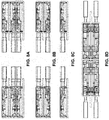
- Figure 8a ⁇ 8d are diagrams of the single-layer, dual-layer, tri-layer, and multi-layer combinations of the feeding network. They provide examples of feeding networks in which a row of feeding electronic networks are laminated to constitute more ports. In addition, the number of ports of the feeding network can be further increased by tiling more networks.
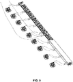
- Figure 9 is a diagram of the connection between the feeding network and an antenna unit.
Landscapes
- Variable-Direction Aerials And Aerial Arrays (AREA)
- Waveguide Switches, Polarizers, And Phase Shifters (AREA)
Claims (6)
- Speisenetzwerk für eine Basisstationsantenne, das Folgendes beinhaltet:einen ersten Phasenverschieber, einen zweiten Phasenverschieber, einen dritten Phasenverschieber und einen vierten Phasenverschieber;einen 3-Wege-Leistungsteiler, der einen Eingangsanschluss zum Verbinden mit einem Speiseporteingang, einen ersten Ausgangsanschluss zum Speisen einer Zentraleinheit der Basisstationsantenne und einen zweiten und dritten Ausgangsanschluss, die mit dem ersten bzw. zweiten Phasenverschieber verbunden sind, umfasst;einen ersten 2-Wege-Leistungsteiler, der einen Eingangsanschluss, der mit dem Ausgangsanschluss des ersten Phasenverschiebers verbunden ist, einen ersten Ausgangsanschluss zum Speisen der Basisstationsantenne und einen zweiten Ausgangsanschluss zum Verbinden mit einem Eingangsanschluss des dritten Phasenverschiebers umfasst; undeinen zweiten 2-Wege-Leistungsteiler, der einen Eingangsanschluss, der mit dem Ausgangsanschluss des zweiten Phasenverschiebers verbunden ist, einen ersten Ausgangsanschluss zum Speisen der Basisstationsantenne und einen zweiten Ausgangsanschluss zum Verbinden mit einem Eingangsanschluss des vierten Phasenverschiebers umfasst;wobei:die Phasenverschieber jeweils eine feste Übertragungsleitung und eine gleitende Übertragungsleitung beinhalten, wobei eine Bewegung der gleitenden Übertragungsleitung die Länge einer Übertragungsleitung, die durch die feste Übertragungsleitung und die gleitende Übertragungsleitung gebildet wird, ändert, wobei jede feste Übertragungsleitung zwei hohle runde Metallrohre (200, 300) umfasst und jede gleitende Übertragungsleitung eine U-förmige Metallstange (100) ist, die auf der Oberfläche mit einer Isolierschicht beschichtet und in die hohlen runden Metallrohre (200, 300) eingesteckt ist; unddas Speisenetzwerk ferner eine integral gebildete Hohlraummetallstruktur (1) mit einer langen Seite umfasst, wobei die Phasenverschieber und die Leistungsteiler in der integral gebildeten Hohlraummetallstruktur (1) angeordnet sind und die ersten Ausgangsanschlüsse der Leistungsteiler entlang der langen Seite der Hohlraummetallstruktur (1) gleichmäßig verteilt sind.
- Speisenetzwerk nach Anspruch 1, wobei der Bereich der Hohlraummetallstruktur (1) ein einzelnes Rechteck, ein einzelnes Rechteck mit einer offenen Seite, ein doppeltes Oben-unten-Rechteck, ein doppeltes Oben-unten-Rechteck mit einer offenen Seite, ein doppeltes Links-rechts-Rechteck, ein doppeltes Links-rechts-Rechteck mit einer offenen Seite oder eine Struktur mit mehreren Hohlräumen, die durch Kombinieren von zwei oder mehr der vorstehenden gebildet ist, ist.
- Speisenetzwerk nach Anspruch 1 oder 2, wobei jeder der Leistungsteiler von einem Luftstreifenleitungstyp in Zweigform ist.
- Speisenetzwerk nach Anspruch 3, wobei die Streifenleitung von flacher, runder oder quadratischer Form ist.
- Speisenetzwerk nach Anspruch 1 oder 2, wobei die verschiedenen Phasenverschieber identisch sind, um Phasenänderungen mit gleichen Unterschieden zu erreichen.
- Speisenetzwerk nach Anspruch 1 oder 2, wobei das Speisenetzwerk eine Vielzahl von Zeilen umfasst, die durch Fliesen und/oder Laminieren kombiniert sind, um ein Phasenverschiebungsspeisenetzwerk mit zusätzlichen Ausgangsanschlüssen zu konstituieren, wobei jede Zeile einen ersten Phasenverschieber, einen zweiten Phasenverschieber, einen dritten Phasenverschieber, einen vierten Phasenverschieber, einen 3-Wege-Leistungsteiler, einen ersten 2-Wege-Leistungsteiler und einen zweiten 2-Wege-Leistungsteiler, die in der in Anspruch 1 genannten Weise verbunden sind, umfasst.
Applications Claiming Priority (1)
| Application Number | Priority Date | Filing Date | Title |
|---|---|---|---|
| PCT/CN2013/088354 WO2015081476A1 (zh) | 2013-12-02 | 2013-12-02 | 基站天线馈电网络 |
Publications (3)
| Publication Number | Publication Date |
|---|---|
| EP2919318A1 EP2919318A1 (de) | 2015-09-16 |
| EP2919318A4 EP2919318A4 (de) | 2016-03-09 |
| EP2919318B1 true EP2919318B1 (de) | 2018-09-12 |
Family
ID=51243479
Family Applications (1)
| Application Number | Title | Priority Date | Filing Date |
|---|---|---|---|
| EP13898577.5A Not-in-force EP2919318B1 (de) | 2013-12-02 | 2013-12-02 | Basisstationsantennenspeisenetzwerk |
Country Status (4)
| Country | Link |
|---|---|
| US (1) | US9559429B2 (de) |
| EP (1) | EP2919318B1 (de) |
| CN (1) | CN103975485B (de) |
| WO (1) | WO2015081476A1 (de) |
Families Citing this family (19)
| Publication number | Priority date | Publication date | Assignee | Title |
|---|---|---|---|---|
| CN203521615U (zh) * | 2013-10-28 | 2014-04-02 | 华为技术有限公司 | 基站天线 |
| CN104362438B (zh) * | 2014-10-30 | 2017-04-26 | 西安欣创电子技术有限公司 | 一种整体式大扫描角波束合成移相器 |
| CN112054314B (zh) | 2015-12-30 | 2023-12-15 | 华为技术有限公司 | 一种阵列天线系统 |
| CN105811109B (zh) * | 2016-03-14 | 2019-01-18 | 武汉虹信通信技术有限责任公司 | 一种高增益大下倾角电调天线 |
| CN105762535B (zh) * | 2016-04-15 | 2018-06-29 | 武汉虹信通信技术有限责任公司 | 一种双系统独立下倾角调整基站电调天线 |
| US11145978B2 (en) | 2016-06-17 | 2021-10-12 | Commscope Technologies Llc | Phased array antennas having multi-level phase shifters |
| CN107181062A (zh) * | 2017-04-28 | 2017-09-19 | 广州司南天线设计研究所有限公司 | 一种用于基站天线的空间立体移相器及移相器组件 |
| CN113013590B (zh) * | 2017-12-11 | 2024-04-09 | 华为技术有限公司 | 一种馈电设备、天线及电子设备 |
| CN108232379A (zh) * | 2017-12-29 | 2018-06-29 | 京信通信系统(中国)有限公司 | 移相结构及天线 |
| CN107968239A (zh) * | 2017-12-29 | 2018-04-27 | 京信通信系统(中国)有限公司 | 移相结构及天线 |
| CN110474135B (zh) * | 2019-08-16 | 2025-05-09 | 广东曼克维通信科技有限公司 | 移相器组件以及基站天线 |
| CN110931921A (zh) * | 2019-12-23 | 2020-03-27 | 南京阜太通信技术有限公司 | 一种应用于5g大规模天线阵列的移相器结构 |
| CN111668605B (zh) * | 2020-07-02 | 2021-07-09 | 中信科移动通信技术股份有限公司 | 用于高铁沿线的电调天线 |
| CN112366445B (zh) * | 2020-10-27 | 2021-07-27 | 东莞市振亮精密科技有限公司 | 一种功分网络、5g天线模块及5g天线模块的装配方法 |
| WO2022235760A1 (en) * | 2021-05-05 | 2022-11-10 | Ossia Inc. | Non-volative, low power phase shifter for tapped transmission lines |
| CN116111343A (zh) * | 2021-11-11 | 2023-05-12 | 华为技术有限公司 | 馈电网络、天线装置及通信设备 |
| CN115513673A (zh) * | 2022-09-08 | 2022-12-23 | 广东分数维无线科技有限公司 | 一种用于相控阵天线的波束扫描方法和装置 |
| CN116435759B (zh) * | 2023-06-14 | 2023-10-27 | 广东盛路通信科技股份有限公司 | 一种基站天线及其指标调节方法 |
| CN119153915B (zh) * | 2024-10-10 | 2026-03-20 | 京信通信技术(广州)有限公司 | 腔体组件及移相器 |
Family Cites Families (11)
| Publication number | Priority date | Publication date | Assignee | Title |
|---|---|---|---|---|
| BE469215A (de) * | 1944-01-28 | |||
| US3493898A (en) * | 1968-04-01 | 1970-02-03 | Raytheon Co | Wideband phase shifter |
| JPH03166803A (ja) * | 1989-11-27 | 1991-07-18 | Kokusai Denshin Denwa Co Ltd <Kdd> | 二周波分離給電円偏波用マイクロストリップアンテナ |
| US5905462A (en) * | 1998-03-18 | 1999-05-18 | Lucent Technologies, Inc. | Steerable phased-array antenna with series feed network |
| US7324060B2 (en) * | 2005-09-01 | 2008-01-29 | Raytheon Company | Power divider having unequal power division and antenna array feed network using such unequal power dividers |
| CN101707271B (zh) * | 2008-12-24 | 2012-01-25 | 广东通宇通讯股份有限公司 | 等相差分多路复合移相器 |
| CN101694897A (zh) * | 2009-10-30 | 2010-04-14 | 网拓(上海)通信技术有限公司 | 移相器 |
| US8872719B2 (en) * | 2009-11-09 | 2014-10-28 | Linear Signal, Inc. | Apparatus, system, and method for integrated modular phased array tile configuration |
| CN102157767B (zh) * | 2011-03-28 | 2014-06-11 | 京信通信系统(中国)有限公司 | 同轴介质移相系统、移相器及移相驱动装置 |
| CN102354775A (zh) * | 2011-08-22 | 2012-02-15 | 广东通宇通讯股份有限公司 | 一种移相装置 |
| CN103280621B (zh) * | 2013-05-03 | 2015-12-23 | 安徽四创电子股份有限公司 | 五等分功分器 |
-
2013
- 2013-12-02 WO PCT/CN2013/088354 patent/WO2015081476A1/zh not_active Ceased
- 2013-12-02 CN CN201380004165.XA patent/CN103975485B/zh active Active
- 2013-12-02 EP EP13898577.5A patent/EP2919318B1/de not_active Not-in-force
-
2014
- 2014-10-01 US US14/503,900 patent/US9559429B2/en active Active
Non-Patent Citations (1)
| Title |
|---|
| None * |
Also Published As
| Publication number | Publication date |
|---|---|
| CN103975485B (zh) | 2015-11-25 |
| CN103975485A (zh) | 2014-08-06 |
| WO2015081476A1 (zh) | 2015-06-11 |
| EP2919318A4 (de) | 2016-03-09 |
| US9559429B2 (en) | 2017-01-31 |
| EP2919318A1 (de) | 2015-09-16 |
| US20150155609A1 (en) | 2015-06-04 |
Similar Documents
| Publication | Publication Date | Title |
|---|---|---|
| EP2919318B1 (de) | Basisstationsantennenspeisenetzwerk | |
| US11165166B2 (en) | Antenna feeding network | |
| CN101707271B (zh) | 等相差分多路复合移相器 | |
| JP5940570B2 (ja) | 基地局通信システムに最適化されたアレイアンテナ | |
| CN106486721B (zh) | 移相器组件 | |
| US20130141186A1 (en) | Recombinant waveguide power combiner / divider | |
| TWI555271B (zh) | Feeder network | |
| CN104103875A (zh) | 移相器及包含移相器的移相组件、移相馈电网络 | |
| US9456514B2 (en) | Phase shifting device | |
| CN107482286B (zh) | 介质移相器及天线 | |
| CN104681896A (zh) | 一种多路一体化介质移相器 | |
| WO2018040837A1 (zh) | 移相器和天线 | |
| CN212485510U (zh) | 集成馈电器的移相器及应用其的天线 | |
| CN113745775B (zh) | 集成馈电器的移相器及应用其的天线 | |
| CN204614906U (zh) | 一种多路一体化介质移相器 | |
| CN114976536A (zh) | 移相合路组件、天线及基站 | |
| CN204011610U (zh) | 移相器及包含移相器的移相组件、移相馈电网络 | |
| CN212542636U (zh) | 一种应用于5g系统的高性能腔体移相器 | |
| CN109888509A (zh) | 大规模阵列天线 | |
| CN109509939B (zh) | Fa/d移相器 | |
| US20140285282A1 (en) | Power dividing phase shifter | |
| WO2017091944A1 (zh) | 微带开关型移相器及应用其的移相模块 | |
| CN206211031U (zh) | 相位平衡单元及功分器电路相位平衡装置 | |
| CN214849055U (zh) | 相位平衡器及基站天线 | |
| CN113422206A (zh) | 天线、基站及移相装置 |
Legal Events
| Date | Code | Title | Description |
|---|---|---|---|
| PUAI | Public reference made under article 153(3) epc to a published international application that has entered the european phase |
Free format text: ORIGINAL CODE: 0009012 |
|
| 17P | Request for examination filed |
Effective date: 20150612 |
|
| AK | Designated contracting states |
Kind code of ref document: A1 Designated state(s): AL AT BE BG CH CY CZ DE DK EE ES FI FR GB GR HR HU IE IS IT LI LT LU LV MC MK MT NL NO PL PT RO RS SE SI SK SM TR |
|
| AX | Request for extension of the european patent |
Extension state: BA ME |
|
| RA4 | Supplementary search report drawn up and despatched (corrected) |
Effective date: 20160208 |
|
| RIC1 | Information provided on ipc code assigned before grant |
Ipc: H01P 1/18 20060101ALI20160202BHEP Ipc: H01Q 21/00 20060101ALI20160202BHEP Ipc: H01Q 3/32 20060101ALI20160202BHEP Ipc: H01Q 1/18 20060101AFI20160202BHEP |
|
| STAA | Information on the status of an ep patent application or granted ep patent |
Free format text: STATUS: EXAMINATION IS IN PROGRESS |
|
| 17Q | First examination report despatched |
Effective date: 20161214 |
|
| DAX | Request for extension of the european patent (deleted) | ||
| GRAP | Despatch of communication of intention to grant a patent |
Free format text: ORIGINAL CODE: EPIDOSNIGR1 |
|
| STAA | Information on the status of an ep patent application or granted ep patent |
Free format text: STATUS: GRANT OF PATENT IS INTENDED |
|
| INTG | Intention to grant announced |
Effective date: 20180702 |
|
| GRAS | Grant fee paid |
Free format text: ORIGINAL CODE: EPIDOSNIGR3 |
|
| GRAA | (expected) grant |
Free format text: ORIGINAL CODE: 0009210 |
|
| STAA | Information on the status of an ep patent application or granted ep patent |
Free format text: STATUS: THE PATENT HAS BEEN GRANTED |
|
| AK | Designated contracting states |
Kind code of ref document: B1 Designated state(s): AL AT BE BG CH CY CZ DE DK EE ES FI FR GB GR HR HU IE IS IT LI LT LU LV MC MK MT NL NO PL PT RO RS SE SI SK SM TR |
|
| REG | Reference to a national code |
Ref country code: GB Ref legal event code: FG4D |
|
| REG | Reference to a national code |
Ref country code: CH Ref legal event code: EP |
|
| REG | Reference to a national code |
Ref country code: IE Ref legal event code: FG4D |
|
| REG | Reference to a national code |
Ref country code: DE Ref legal event code: R096 Ref document number: 602013043735 Country of ref document: DE |
|
| REG | Reference to a national code |
Ref country code: AT Ref legal event code: REF Ref document number: 1041668 Country of ref document: AT Kind code of ref document: T Effective date: 20181015 |
|
| REG | Reference to a national code |
Ref country code: NL Ref legal event code: MP Effective date: 20180912 |
|
| REG | Reference to a national code |
Ref country code: LT Ref legal event code: MG4D |
|
| PG25 | Lapsed in a contracting state [announced via postgrant information from national office to epo] |
Ref country code: GR Free format text: LAPSE BECAUSE OF FAILURE TO SUBMIT A TRANSLATION OF THE DESCRIPTION OR TO PAY THE FEE WITHIN THE PRESCRIBED TIME-LIMIT Effective date: 20181213 Ref country code: SE Free format text: LAPSE BECAUSE OF FAILURE TO SUBMIT A TRANSLATION OF THE DESCRIPTION OR TO PAY THE FEE WITHIN THE PRESCRIBED TIME-LIMIT Effective date: 20180912 Ref country code: RS Free format text: LAPSE BECAUSE OF FAILURE TO SUBMIT A TRANSLATION OF THE DESCRIPTION OR TO PAY THE FEE WITHIN THE PRESCRIBED TIME-LIMIT Effective date: 20180912 Ref country code: LT Free format text: LAPSE BECAUSE OF FAILURE TO SUBMIT A TRANSLATION OF THE DESCRIPTION OR TO PAY THE FEE WITHIN THE PRESCRIBED TIME-LIMIT Effective date: 20180912 Ref country code: NO Free format text: LAPSE BECAUSE OF FAILURE TO SUBMIT A TRANSLATION OF THE DESCRIPTION OR TO PAY THE FEE WITHIN THE PRESCRIBED TIME-LIMIT Effective date: 20181212 Ref country code: BG Free format text: LAPSE BECAUSE OF FAILURE TO SUBMIT A TRANSLATION OF THE DESCRIPTION OR TO PAY THE FEE WITHIN THE PRESCRIBED TIME-LIMIT Effective date: 20181212 |
|
| PG25 | Lapsed in a contracting state [announced via postgrant information from national office to epo] |
Ref country code: AL Free format text: LAPSE BECAUSE OF FAILURE TO SUBMIT A TRANSLATION OF THE DESCRIPTION OR TO PAY THE FEE WITHIN THE PRESCRIBED TIME-LIMIT Effective date: 20180912 Ref country code: HR Free format text: LAPSE BECAUSE OF FAILURE TO SUBMIT A TRANSLATION OF THE DESCRIPTION OR TO PAY THE FEE WITHIN THE PRESCRIBED TIME-LIMIT Effective date: 20180912 Ref country code: LV Free format text: LAPSE BECAUSE OF FAILURE TO SUBMIT A TRANSLATION OF THE DESCRIPTION OR TO PAY THE FEE WITHIN THE PRESCRIBED TIME-LIMIT Effective date: 20180912 |
|
| REG | Reference to a national code |
Ref country code: AT Ref legal event code: MK05 Ref document number: 1041668 Country of ref document: AT Kind code of ref document: T Effective date: 20180912 |
|
| PG25 | Lapsed in a contracting state [announced via postgrant information from national office to epo] |
Ref country code: IS Free format text: LAPSE BECAUSE OF FAILURE TO SUBMIT A TRANSLATION OF THE DESCRIPTION OR TO PAY THE FEE WITHIN THE PRESCRIBED TIME-LIMIT Effective date: 20190112 Ref country code: AT Free format text: LAPSE BECAUSE OF FAILURE TO SUBMIT A TRANSLATION OF THE DESCRIPTION OR TO PAY THE FEE WITHIN THE PRESCRIBED TIME-LIMIT Effective date: 20180912 Ref country code: EE Free format text: LAPSE BECAUSE OF FAILURE TO SUBMIT A TRANSLATION OF THE DESCRIPTION OR TO PAY THE FEE WITHIN THE PRESCRIBED TIME-LIMIT Effective date: 20180912 Ref country code: PL Free format text: LAPSE BECAUSE OF FAILURE TO SUBMIT A TRANSLATION OF THE DESCRIPTION OR TO PAY THE FEE WITHIN THE PRESCRIBED TIME-LIMIT Effective date: 20180912 Ref country code: CZ Free format text: LAPSE BECAUSE OF FAILURE TO SUBMIT A TRANSLATION OF THE DESCRIPTION OR TO PAY THE FEE WITHIN THE PRESCRIBED TIME-LIMIT Effective date: 20180912 Ref country code: ES Free format text: LAPSE BECAUSE OF FAILURE TO SUBMIT A TRANSLATION OF THE DESCRIPTION OR TO PAY THE FEE WITHIN THE PRESCRIBED TIME-LIMIT Effective date: 20180912 Ref country code: NL Free format text: LAPSE BECAUSE OF FAILURE TO SUBMIT A TRANSLATION OF THE DESCRIPTION OR TO PAY THE FEE WITHIN THE PRESCRIBED TIME-LIMIT Effective date: 20180912 Ref country code: RO Free format text: LAPSE BECAUSE OF FAILURE TO SUBMIT A TRANSLATION OF THE DESCRIPTION OR TO PAY THE FEE WITHIN THE PRESCRIBED TIME-LIMIT Effective date: 20180912 Ref country code: IT Free format text: LAPSE BECAUSE OF FAILURE TO SUBMIT A TRANSLATION OF THE DESCRIPTION OR TO PAY THE FEE WITHIN THE PRESCRIBED TIME-LIMIT Effective date: 20180912 |
|
| PG25 | Lapsed in a contracting state [announced via postgrant information from national office to epo] |
Ref country code: SM Free format text: LAPSE BECAUSE OF FAILURE TO SUBMIT A TRANSLATION OF THE DESCRIPTION OR TO PAY THE FEE WITHIN THE PRESCRIBED TIME-LIMIT Effective date: 20180912 Ref country code: PT Free format text: LAPSE BECAUSE OF FAILURE TO SUBMIT A TRANSLATION OF THE DESCRIPTION OR TO PAY THE FEE WITHIN THE PRESCRIBED TIME-LIMIT Effective date: 20190112 Ref country code: SK Free format text: LAPSE BECAUSE OF FAILURE TO SUBMIT A TRANSLATION OF THE DESCRIPTION OR TO PAY THE FEE WITHIN THE PRESCRIBED TIME-LIMIT Effective date: 20180912 |
|
| REG | Reference to a national code |
Ref country code: DE Ref legal event code: R097 Ref document number: 602013043735 Country of ref document: DE |
|
| REG | Reference to a national code |
Ref country code: DE Ref legal event code: R119 Ref document number: 602013043735 Country of ref document: DE |
|
| PLBE | No opposition filed within time limit |
Free format text: ORIGINAL CODE: 0009261 |
|
| STAA | Information on the status of an ep patent application or granted ep patent |
Free format text: STATUS: NO OPPOSITION FILED WITHIN TIME LIMIT |
|
| PG25 | Lapsed in a contracting state [announced via postgrant information from national office to epo] |
Ref country code: DK Free format text: LAPSE BECAUSE OF FAILURE TO SUBMIT A TRANSLATION OF THE DESCRIPTION OR TO PAY THE FEE WITHIN THE PRESCRIBED TIME-LIMIT Effective date: 20180912 |
|
| REG | Reference to a national code |
Ref country code: CH Ref legal event code: PL |
|
| 26N | No opposition filed |
Effective date: 20190613 |
|
| GBPC | Gb: european patent ceased through non-payment of renewal fee |
Effective date: 20181212 |
|
| PG25 | Lapsed in a contracting state [announced via postgrant information from national office to epo] |
Ref country code: LU Free format text: LAPSE BECAUSE OF NON-PAYMENT OF DUE FEES Effective date: 20181202 Ref country code: SI Free format text: LAPSE BECAUSE OF FAILURE TO SUBMIT A TRANSLATION OF THE DESCRIPTION OR TO PAY THE FEE WITHIN THE PRESCRIBED TIME-LIMIT Effective date: 20180912 Ref country code: MC Free format text: LAPSE BECAUSE OF FAILURE TO SUBMIT A TRANSLATION OF THE DESCRIPTION OR TO PAY THE FEE WITHIN THE PRESCRIBED TIME-LIMIT Effective date: 20180912 |
|
| REG | Reference to a national code |
Ref country code: IE Ref legal event code: MM4A |
|
| REG | Reference to a national code |
Ref country code: BE Ref legal event code: MM Effective date: 20181231 |
|
| PG25 | Lapsed in a contracting state [announced via postgrant information from national office to epo] |
Ref country code: FR Free format text: LAPSE BECAUSE OF NON-PAYMENT OF DUE FEES Effective date: 20181231 Ref country code: DE Free format text: LAPSE BECAUSE OF NON-PAYMENT OF DUE FEES Effective date: 20190702 Ref country code: IE Free format text: LAPSE BECAUSE OF NON-PAYMENT OF DUE FEES Effective date: 20181202 |
|
| PG25 | Lapsed in a contracting state [announced via postgrant information from national office to epo] |
Ref country code: BE Free format text: LAPSE BECAUSE OF NON-PAYMENT OF DUE FEES Effective date: 20181231 |
|
| PG25 | Lapsed in a contracting state [announced via postgrant information from national office to epo] |
Ref country code: GB Free format text: LAPSE BECAUSE OF NON-PAYMENT OF DUE FEES Effective date: 20181212 Ref country code: LI Free format text: LAPSE BECAUSE OF NON-PAYMENT OF DUE FEES Effective date: 20181231 Ref country code: CH Free format text: LAPSE BECAUSE OF NON-PAYMENT OF DUE FEES Effective date: 20181231 |
|
| PG25 | Lapsed in a contracting state [announced via postgrant information from national office to epo] |
Ref country code: MT Free format text: LAPSE BECAUSE OF NON-PAYMENT OF DUE FEES Effective date: 20181202 |
|
| PG25 | Lapsed in a contracting state [announced via postgrant information from national office to epo] |
Ref country code: TR Free format text: LAPSE BECAUSE OF FAILURE TO SUBMIT A TRANSLATION OF THE DESCRIPTION OR TO PAY THE FEE WITHIN THE PRESCRIBED TIME-LIMIT Effective date: 20180912 |
|
| PG25 | Lapsed in a contracting state [announced via postgrant information from national office to epo] |
Ref country code: CY Free format text: LAPSE BECAUSE OF FAILURE TO SUBMIT A TRANSLATION OF THE DESCRIPTION OR TO PAY THE FEE WITHIN THE PRESCRIBED TIME-LIMIT Effective date: 20180912 Ref country code: HU Free format text: LAPSE BECAUSE OF FAILURE TO SUBMIT A TRANSLATION OF THE DESCRIPTION OR TO PAY THE FEE WITHIN THE PRESCRIBED TIME-LIMIT; INVALID AB INITIO Effective date: 20131202 Ref country code: MK Free format text: LAPSE BECAUSE OF NON-PAYMENT OF DUE FEES Effective date: 20180912 |
|
| PGFP | Annual fee paid to national office [announced via postgrant information from national office to epo] |
Ref country code: FI Payment date: 20230120 Year of fee payment: 10 |
|
| PG25 | Lapsed in a contracting state [announced via postgrant information from national office to epo] |
Ref country code: FI Free format text: LAPSE BECAUSE OF NON-PAYMENT OF DUE FEES Effective date: 20231202 |