EP2919938B1 - Tête de dispositif de coupe bidirectionnelle pour fabrication d'engrenage - Google Patents
Tête de dispositif de coupe bidirectionnelle pour fabrication d'engrenage Download PDFInfo
- Publication number
- EP2919938B1 EP2919938B1 EP13801916.1A EP13801916A EP2919938B1 EP 2919938 B1 EP2919938 B1 EP 2919938B1 EP 13801916 A EP13801916 A EP 13801916A EP 2919938 B1 EP2919938 B1 EP 2919938B1
- Authority
- EP
- European Patent Office
- Prior art keywords
- cutter head
- cutting
- positioning slots
- blade positioning
- cutting blades
- Prior art date
- Legal status (The legal status is an assumption and is not a legal conclusion. Google has not performed a legal analysis and makes no representation as to the accuracy of the status listed.)
- Active
Links
Images
Classifications
-
- B—PERFORMING OPERATIONS; TRANSPORTING
- B23—MACHINE TOOLS; METAL-WORKING NOT OTHERWISE PROVIDED FOR
- B23F—MAKING GEARS OR TOOTHED RACKS
- B23F21/00—Tools specially adapted for use in machines for manufacturing gear teeth
- B23F21/12—Milling tools
- B23F21/16—Hobs
- B23F21/163—Hobs with inserted cutting elements
- B23F21/166—Hobs with inserted cutting elements in exchangeable arrangement
-
- B—PERFORMING OPERATIONS; TRANSPORTING
- B23—MACHINE TOOLS; METAL-WORKING NOT OTHERWISE PROVIDED FOR
- B23F—MAKING GEARS OR TOOTHED RACKS
- B23F21/00—Tools specially adapted for use in machines for manufacturing gear teeth
- B23F21/12—Milling tools
- B23F21/22—Face-mills for longitudinally-curved gear teeth
- B23F21/223—Face-mills for longitudinally-curved gear teeth with inserted cutting elements
- B23F21/226—Face-mills for longitudinally-curved gear teeth with inserted cutting elements in exchangeable arrangement
-
- B—PERFORMING OPERATIONS; TRANSPORTING
- B23—MACHINE TOOLS; METAL-WORKING NOT OTHERWISE PROVIDED FOR
- B23F—MAKING GEARS OR TOOTHED RACKS
- B23F21/00—Tools specially adapted for use in machines for manufacturing gear teeth
- B23F21/12—Milling tools
- B23F21/22—Face-mills for longitudinally-curved gear teeth
- B23F21/23—Face-mills for longitudinally-curved gear teeth with cutter teeth arranged on a spiral curve for continuous generating processes
- B23F21/233—Face-mills for longitudinally-curved gear teeth with cutter teeth arranged on a spiral curve for continuous generating processes with inserted cutting elements
- B23F21/236—Face-mills for longitudinally-curved gear teeth with cutter teeth arranged on a spiral curve for continuous generating processes with inserted cutting elements in exchangeable arrangement
-
- Y—GENERAL TAGGING OF NEW TECHNOLOGICAL DEVELOPMENTS; GENERAL TAGGING OF CROSS-SECTIONAL TECHNOLOGIES SPANNING OVER SEVERAL SECTIONS OF THE IPC; TECHNICAL SUBJECTS COVERED BY FORMER USPC CROSS-REFERENCE ART COLLECTIONS [XRACs] AND DIGESTS
- Y10—TECHNICAL SUBJECTS COVERED BY FORMER USPC
- Y10T—TECHNICAL SUBJECTS COVERED BY FORMER US CLASSIFICATION
- Y10T407/00—Cutters, for shaping
- Y10T407/17—Gear cutting tool
- Y10T407/1705—Face mill gear cutting tool
- Y10T407/171—Adjustable teeth
-
- Y—GENERAL TAGGING OF NEW TECHNOLOGICAL DEVELOPMENTS; GENERAL TAGGING OF CROSS-SECTIONAL TECHNOLOGIES SPANNING OVER SEVERAL SECTIONS OF THE IPC; TECHNICAL SUBJECTS COVERED BY FORMER USPC CROSS-REFERENCE ART COLLECTIONS [XRACs] AND DIGESTS
- Y10—TECHNICAL SUBJECTS COVERED BY FORMER USPC
- Y10T—TECHNICAL SUBJECTS COVERED BY FORMER US CLASSIFICATION
- Y10T407/00—Cutters, for shaping
- Y10T407/17—Gear cutting tool
- Y10T407/174—Gear generating, revolving shaper cutting tool
-
- Y—GENERAL TAGGING OF NEW TECHNOLOGICAL DEVELOPMENTS; GENERAL TAGGING OF CROSS-SECTIONAL TECHNOLOGIES SPANNING OVER SEVERAL SECTIONS OF THE IPC; TECHNICAL SUBJECTS COVERED BY FORMER USPC CROSS-REFERENCE ART COLLECTIONS [XRACs] AND DIGESTS
- Y10—TECHNICAL SUBJECTS COVERED BY FORMER USPC
- Y10T—TECHNICAL SUBJECTS COVERED BY FORMER US CLASSIFICATION
- Y10T409/00—Gear cutting, milling, or planing
- Y10T409/10—Gear cutting
- Y10T409/101431—Gear tooth shape generating
- Y10T409/10159—Hobbing
- Y10T409/101749—Process
- Y10T409/101908—Generating tooth for bevel gear
Definitions
- the present invention is directed generally to cutting tools for cutting bevel and hypoid gears.
- the present invention is directed to cutter heads for manufacturing bevel gears.
- the cutting tools utilized are primarily face mill or face hob cutters.
- the cutters generally comprise cutting blades formed from a length of bar stock material (e.g. high-speed steel or carbide) having a base or shank portion and a cutting end portion, including at least one cutting edge, at one end, or at both ends, of the base or shank.
- a plurality of cutting blades are usually arranged about a cutter head with the cutting ends of the blades projecting from a face of the cutter head.
- Such types of cutting tools are well known in the art of gear manufacture.
- Face milling cutters In face mill cutters, a plurality of cutting blades are arranged about a circle in a cutter head such that one tooth slot is formed with each plunge of the cutter and the cutter must be withdrawn and the workpiece indexed to the next tooth slot position in order to form the next tooth slot (i.e. intermittent indexing).
- Face milling cutters usually comprise alternating inside and outside cutting blades that cut, respectively, inside and outside portions of a tooth slot. Face mill cutters may also comprise successive cutting blades that remove stock material from the entire tooth slot, such as is disclosed in US 1,236,834 to Gleason , US 1,667,299 to Wildhaber or US 2007/0011855 to Ribbeck . If desired, one or more "bottom” cutting blades may be included for removal of stock material from the bottom or root portion of a tooth slot.
- Face hobbing comprises cutting blades arranged about a cutter, not in line with each other, but in groups, with usually two or three cutting blades per group.
- the blade pair comprises an inner cutting blade and an outer cutting blade.
- a "bottom" cutting blade is included along with an inside and outside cutting blade.
- face hobbing comprises each successive group of cutting blades passing through respective successive tooth slot with each blade in the group forming a cut completely along the longitudinal portion of the tooth slot.
- the cutter and the workpiece rotate in a timed relationship with each other thereby allowing continual indexing of the workpiece and continual formation of each tooth slot of the gear.
- a single plunge of the cutting tool results in all tooth slots of the workpiece being formed (i.e. continuous indexing).
- Cutting blades may be made of any suitable tool material such as conventional or powered metal hardened high speed steel (HSS) of any alloy composition (such as, for example, M2, M4, Rex 45, Rex 54, Rex 76, T15, Rex 121 or others) or made of carbide hard metal of any alloy composition, such as P and K grades.
- the wear surfaces of cutting blades may be coated (and recoated after sharpening) with PVD single or multi-layer coatings consisting of any commercially available wear coating or combination of wear coatings such as, for example, TiN, TiCN, TiAIN, AITiN, CrAIN, ZrN, CrN and others.
- Gear cutting operations may be performed utilizing a coolant or lubricant (i.e. wet cutting) or may be carried out in the absence of any such coolant or lubricant (i.e. dry cutting). Dry cutting operations are usually performed utilizing cutting blades comprising carbide materials.
- a left hand cutter (having blades which cut in a counterclockwise direction when viewing the back of the cutter) is utilized to cut a left hand gear.
- the "hand" (left or right) of a gear is the direction of inclination of the gear teeth as viewed from the face of the gear (ring gear or pinion for a bevel gear set) at the 12 o'clock position.
- the cutting blades of a face hobbing cutter are arranged in blade groups, with the blades of one group passing through one slot, while the blades of the following group pass through the following slot of the part.
- This cutting sequence requires a certain arrangement (regarding radial location and tangential offset) of the blades in one group, which repeats for each group.
- the cutter to cut a right hand part is a mirror image of the left hand cutter regarding cutting direction and blade orientation within one blade group.
- a left hand pinion mates with a right hand gear, which in face hobbing requires a pair of cutters (one left hand and one right hand) in order to cut the two mating members (pinion and ring gear) of a bevel gear set.
- the present invention eliminates the need for two cutter heads particularly for face hobbing.
- a single cutter head is proposed thereby reducing the expense of producing mating members of a gear set.
- DE 10 2007 038 935 A1 discloses a cutter head for cutting bevel gears having insertion slots with cross section in form of a half-circle in which the cutting blades are held by the force of clamping screws acting on the blades by intermediate action of clamping plates.
- CN 201 543 918 U discloses a gear milling cutter to contemporaneously cut two adjacent tooth slots of a work piece.
- the invention provides a cutter head according to claim 1 and a method of manufacturing a bevel or hypoid gear work piece according to claim 13. Further preferable embodiments of the cutter heads are given in claims 2 to 12.
- the invention comprises a cutter head having cutting blade positioning slots wherein a portion of the positioning slots accommodate cutting blades for right-hand cutting and another portion of the positioning slots accommodate cutting blades for left-hand cutting.
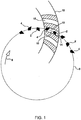
- Figure 1 represents an example of an alternating blade type face milling cutter comprising inside cutting blades 2 and outside cutting blades 4 arranged in line with one another (e.g. on circle 6) on a cutter head (not shown).
- the cutting blades 2, 4 are rotated in the direction of arrow 8 to form a tooth slot 10 of a work piece represented at 12.
- Inside cutting blades 2 cut the respective inside flank surface 14 of the tooth slot 10 while outside cutting blades 4 cut the respective outside flank surface 16 of the tooth slot 10. All cutting blades 2, 4 of the cutter pass through a single slot of the workpiece during cutter rotation.
- the cutting blades 2, 4 are fed in, relative to the work piece 12, until a final tooth slot depth is reached.
- the cutter is then withdrawn, the work piece is indexed to the position of another tooth slot (18 for example), and cutting is resumed. This sequence is repeated until all tooth slots of the workpiece have been formed.
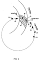
- FIG 2 illustrates an example of the face hobbing method of gear manufacture.
- Face hobbing comprises cutting blades arranged about a cutter, not in line with each other, but in groups, with usually two or three cutting blades per group.
- two cutting blades per group (outside cutting blade 22 and inside cutting blade 24) are shown.
- face hobbing comprises each successive group of cutting blades 22, 24 passing through respective successive tooth slots with each blade in the group forming a cut completely along the longitudinal portion of the tooth slot.
- the group of cutting blades 22' and 24' cut respective outside surface 28 and inside surface 30 of tooth slot 26 while the successive group of cutting blades 22" and 24" cut corresponding surfaces in the next tooth slot 32.
- the cutter and the workpiece rotate in a timed relationship with each other thereby allowing continual indexing of the workpiece and continual formation of each tooth slot of the gear.
- a single plunge of the cutting tool results in all tooth slots of the workpiece being formed.
- two cutters left hand and right hand
- the inventor has discovered that considerable savings can be realized by utilizing a single cutter head for both right hand and left hand cutting.
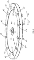
- Figure 3 illustrates an embodiment of the present invention comprising a face hobbing cutter head 40, rotatable about axis A ( Figure 4 ), having cutting blades projecting from a front face thereof.
- the cutter head 40 which, for example, conventionally comprises only inside cutting blades 42 and outside cutting blades 44 (three blade groups shown in Figure 1 ) for right hand "RH” cutting has been modified according to the invention to also include cutter head blade positioning slots that accommodate cutting blades for left hand “LH” cutting.
- Such left hand cutting blades comprise inside cutting blades 46 and outside cutting blades 48.
- Figure 3 illustrates cutting blades having five sides, the present invention is not limited thereto. Any cutting blade cross-sectional shape (e.g. four-sided, circular, semi-circular, etc.) is contemplated by the invention.
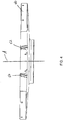
- Figure 4 shows a cross-section of the cutter head of Figure 3 wherein cutting blade positioning slots 50 (one shown) are oriented at a particular hook angle, ⁇ 1 , (depending upon the particular process and/or the gear being cut) for right hand cutting while blade mounting slots 52 (one shown) for left hand cutting are oriented at a particular hook angle, ⁇ 2 , (depending upon the particular process and/or the gear being cut).
- Hook angles ⁇ 1 and ⁇ 2 may or may not be equal. It should be noted that hook angles of zero degrees are also contemplated by the present invention especially in face hobbing cutter heads wherein an offset exists between the cutter axis and the blade slot bottom radius.
- Figures 3 and 4 illustrate a face hobbing cutter
- the invention is equally applicable to face milling cutters including those face milling cutters having inside and outside cutting blades as well as those face milling cutters having cutting blades wherein each blade cuts the entire width of a tooth slot.
- the primary aspect of the invention is that a cutter head be provided with appropriate blade positioning slots such that the same cutter head may be utilized as a right-hand cutter and as a left-hand cutter.
- Figure 3 illustrates a cutter having three sets of inside and outside cutting blades (right and left hand)
- any number of cutting blade sets may be present depending upon the size and strength of the cutter head and the properties and geometry of the particular gear being cut.
- certain face hobbing cutter heads such as those designed to cut bevel gears having diameters of 800 mm or less, may typically have five sets of cutting blades (either right or left hand) since sufficient cutter head space is usually available to include an additional five sets of cutter blades of the "other" hand, whereby both right hand and left hand cutting may be performed by the same cutter head, while still having a cutter head of sufficient strength to perform the cutting.
- the number of right hand blade positioning slots and the number of left hand blade positioning slots need not be equal.
- Figure 3 shows an alternating right-hand and left-hand blade arrangement based on individual blades (e.g. outside RH cutting blade 44 followed by outside LH cutting blade 48), the invention also contemplates alternating pairs of cutting blades, for example, inside and outside right-hand cutting blades followed by inside and outside left-hand cutting blades) or other combinations or sequences of right-hand and left-hand hand cutting blades. Furthermore, the invention is not limited to equal spacing between cutting blades but also encompasses unequal spacing between individual cutting blades or groups of cutting blades of either hand or both hands of cutter rotation.
- Cutting blades for both right hand and left hand cutting may reside in the cutter head at the same time although it is not necessary.
- the left hand cutting blades may be located in a withdrawn position in the cutter head so that they do not come in contact with a workpiece during the right hand cutting.
- the right hand cutting blades are "pushed back" to a withdrawn position and the left hand cutting blades are advanced to their proper position for left hand cutting to be performed on a workpiece.
- those cutting blade positioning slots not being used for a particular hand of cutting may be left empty or may be plugged to prevent contamination due to byproducts of the cutting process.
- the repositioning of cutting blades to transition from one hand of cutting to the other may take place while the cutter head remains secured to the tool spindle of the machine.
- the cutter head may be removed from the machine to reposition the cutting blades and then returned to position on the machine.
Landscapes
- Engineering & Computer Science (AREA)
- Mechanical Engineering (AREA)
- Gear Processing (AREA)
Claims (13)
- Tête de coupe de dispositif à tailler les engrenages, pour la taille d'engrenages coniques ou hypoïdes, ladite tête de coupe étant de forme générale circulaire et rotative sur un axe, ladite tête de coupe comprenant :une pluralité de fentes d'installation de lame de coupe agencées dans ladite tête de coupe ;caractérisé en ce qu'une première partie de ladite pluralité de fentes d'installation de lame est orientée pour recevoir des lames de coupe de manière que ladite tête de coupe puisse opérer pour une coupe à droite, et une deuxième partie de ladite pluralité de fentes d'installation de lame est orientée pour recevoir des lames de coupe de manière que ladite tête de coupe puisse opérer pour une coupe à gauche.
- Tête de coupe selon la revendication 1, dans laquelle ladite première partie des fentes d'installation de lame est orientée selon un angle de coupe.
- Tête de coupe selon la revendication 1 ou 2, dans laquelle ladite deuxième partie des fentes d'installation de lame est orientée selon un angle de coupe.
- Tête de coupe selon l'une quelconque des revendications 1 à 3, dans laquelle lesdites fentes d'installation de lame sont agencées de manière que ladite tête de coupe puisse opérer en vue d'un surfaçage.
- Tête de coupe selon l'une quelconque des revendications 1 à 3, dans laquelle lesdites fentes d'installation de lame sont agencées de manière que ladite tête de coupe puisse opérer en vue d'un taillage en génération continue.
- Tête de coupe selon l'une quelconque des revendications précédentes, dans laquelle lesdites fentes d'installation de lame sont agencées de manière que ladite tête de coupe puisse opérer avec des lames de coupe intérieure et/ou des lames de coupe extérieures.
- Tête de coupe selon l'une quelconque des revendications 1 à 5, dans laquelle lesdites fentes d'installation de lame sont agencées de manière que ladite tête de coupe puisse opérer avec des lames de coupe à pleine largeur de fente.
- Tête de coupe selon l'une quelconque des revendications précédentes, dans laquelle lesdites fentes d'installation de lame sont équidistantes sur ladite tête de coupe.
- Tête de coupe selon l'une quelconque des revendications précédentes, dans laquelle le nombre des fentes d'installation de lame pour une coupe à droite et le nombre des fentes d'installation de lame pour une coupe à gauche sont identiques.
- Tête de coupe selon l'une quelconque des revendications précédentes, dans laquelle les fentes d'installation de lame pour une coupe à droite et les fentes d'installation de lame pour une coupe à gauche sont agencées en alternance sur ladite tête de coupe.
- Tête de coupe selon l'une quelconque des revendications précédentes, dans laquelle lesdites fentes d'installation de lame reçoivent des lames de coupe dont la forme en coupe transversale présente quatre ou cinq côtés.
- Tête de coupe selon l'une quelconque des revendications précédentes, dans laquelle lesdites fentes d'installation de lame reçoivent des lames de coupe dont la forme en coupe transversale est circulaire ou semi-circulaire.
- Procédé de production de pièces d'usinage pour engrenages coniques ou hypoïdes, comprenant :la disposition d'une tête de dispositif de coupe selon l'une quelconque des revendications 1 à 12,la réalisation d'un processus de coupe à droite sur une pièce d'usinage au moyen de la tête de coupe dotée de lames de coupe à droite reçues dans les fentes d'installation de lame de ladite première partie, etla réalisation d'un processus de coupe à gauche sur une autre pièce d'usinage avec la même tête de coupe dotée de lames de coupe reçues dans les fentes d'installation de lame de ladite deuxième partie.
Applications Claiming Priority (2)
| Application Number | Priority Date | Filing Date | Title |
|---|---|---|---|
| US201261725594P | 2012-11-13 | 2012-11-13 | |
| PCT/US2013/069021 WO2014078174A1 (fr) | 2012-11-13 | 2013-11-08 | Tête de dispositif de coupe bidirectionnelle pour fabrication d'engrenage |
Publications (2)
| Publication Number | Publication Date |
|---|---|
| EP2919938A1 EP2919938A1 (fr) | 2015-09-23 |
| EP2919938B1 true EP2919938B1 (fr) | 2019-01-09 |
Family
ID=49724654
Family Applications (1)
| Application Number | Title | Priority Date | Filing Date |
|---|---|---|---|
| EP13801916.1A Active EP2919938B1 (fr) | 2012-11-13 | 2013-11-08 | Tête de dispositif de coupe bidirectionnelle pour fabrication d'engrenage |
Country Status (5)
| Country | Link |
|---|---|
| US (1) | US10065254B2 (fr) |
| EP (1) | EP2919938B1 (fr) |
| JP (1) | JP6527823B2 (fr) |
| CN (1) | CN104781028B (fr) |
| WO (1) | WO2014078174A1 (fr) |
Families Citing this family (3)
| Publication number | Priority date | Publication date | Assignee | Title |
|---|---|---|---|---|
| EP3352937B1 (fr) * | 2015-09-23 | 2023-04-26 | The Gleason Works | Compatibilité de lames à trois faces |
| CN106735494B (zh) * | 2016-11-21 | 2018-09-28 | 株洲钻石切削刀具股份有限公司 | 具有防飞功能的铣削刀具 |
| US11173559B2 (en) * | 2017-07-13 | 2021-11-16 | The Gleason Works | Bevel gear cutter and blade consolidation |
Family Cites Families (29)
| Publication number | Priority date | Publication date | Assignee | Title |
|---|---|---|---|---|
| US1236834A (en) | 1913-05-26 | 1917-08-14 | Gleason Works | Gear-cutter. |
| US1667299A (en) | 1927-03-16 | 1928-04-24 | Gleason Works | Gear cutter |
| US1927409A (en) * | 1928-05-01 | 1933-09-19 | Ex Cell O Aircraft & Tool Corp | Milling cutter |
| GB537399A (en) * | 1940-10-04 | 1941-06-19 | Craven Brothers Manchester Ltd | Improved tool for cutting gears having curved teeth |
| GB695249A (en) * | 1950-07-06 | 1953-08-05 | Oerlikon Buehrle Ag | Improvements in or relating to cutter head for spiral bevel gears and the like |
| CH534020A (de) | 1971-02-12 | 1973-02-28 | Oerlikon Buehrle Ag | Stirnmesserkopf |
| US4038732A (en) * | 1976-09-15 | 1977-08-02 | The Gleason Works | Versatile cutting tool for gear manufacture |
| US4565474A (en) * | 1980-11-01 | 1986-01-21 | The Ingersoll Milling Machine Company | Method of generating involute tooth forms with a milling cutter |
| JPS58117314U (ja) * | 1982-02-02 | 1983-08-10 | トヨタ自動車株式会社 | かさ歯車用歯切カツタのブレ−ド形状 |
| US4525108A (en) | 1982-11-18 | 1985-06-25 | The Gleason Works | Cutter and method for gear manufacture |
| US4575285A (en) | 1984-11-19 | 1986-03-11 | The Gleason Works | Cutting tool and method of manufacture |
| US4575286A (en) | 1984-11-19 | 1986-03-11 | The Gleason Works | Gear cutter assembly |
| US5145294A (en) * | 1991-03-15 | 1992-09-08 | National Carbide Outlet, Inc. | Milling cutter capable of using indexable inserts of various shapes |
| JP3002542B2 (ja) * | 1993-03-24 | 2000-01-24 | ザ グリーソン ワークス | カッティングブレードを形成する方法 |
| US5542794A (en) * | 1994-11-09 | 1996-08-06 | Kennametal Inc. | Multi-handed milling cutter having indexable wedges and inserts |
| DE19624685C1 (de) * | 1996-06-20 | 1997-02-20 | Oerlikon Geartec Ag | Rundstabmesser und insbesondere dafür vorgesehener Messerkopf |
| CA2370833A1 (fr) * | 1999-05-05 | 2000-11-09 | The Gleason Works | Outil de coupe pour la fabrication d'engrenages tailles par generation |
| JP2001347412A (ja) * | 2000-04-06 | 2001-12-18 | Yutaka Seimitsu Kogyo Ltd | 正面カッタおよびカッタ用ブレード |
| US6669415B2 (en) | 2001-02-16 | 2003-12-30 | The Gleason Works | Machine for producing bevel gears |
| DE10112165B4 (de) * | 2001-03-12 | 2004-02-05 | Rainer Richardt | Stabmesserkopf zum Verzahnen |
| US6896017B2 (en) * | 2002-10-22 | 2005-05-24 | Moulder Services, Inc. | Rotatable cutting tool |
| ES2264115T5 (es) | 2003-05-22 | 2011-06-16 | Klingelnberg Gmbh | Método , cuchilla de barra y uso de la misma para fresar ruedas dentadas cónicas helicoidales y ruedas dentadas hipoides. |
| JP2008279574A (ja) * | 2007-05-14 | 2008-11-20 | Honda Motor Co Ltd | ブレード |
| DE102007038935B4 (de) * | 2007-08-17 | 2009-08-27 | Richardt, Renate | Stabmesserkopf und entsprechende Werkzeugmaschine |
| PL2181789T3 (pl) * | 2008-10-30 | 2011-11-30 | Klingelnberg Ag | Uniwersalna trzonkowa głowica frezowa i jej zastosowanie |
| JP2010179409A (ja) * | 2009-02-05 | 2010-08-19 | Jtekt Corp | 切削工具 |
| CN201543918U (zh) * | 2009-10-27 | 2010-08-11 | 南京工业大学 | 一种可转位成形双刀盘齿轮铣刀 |
| US8807884B2 (en) * | 2009-12-18 | 2014-08-19 | Kennametal Inc. | Tool holder for multiple differently-shaped cutting inserts |
| US9289839B2 (en) * | 2009-12-22 | 2016-03-22 | The Gleason Works | Method for manufacturing bevel gears |
-
2013
- 2013-11-08 EP EP13801916.1A patent/EP2919938B1/fr active Active
- 2013-11-08 CN CN201380059064.2A patent/CN104781028B/zh not_active Expired - Fee Related
- 2013-11-08 JP JP2015542706A patent/JP6527823B2/ja not_active Expired - Fee Related
- 2013-11-08 WO PCT/US2013/069021 patent/WO2014078174A1/fr not_active Ceased
- 2013-11-08 US US14/440,666 patent/US10065254B2/en not_active Expired - Fee Related
Non-Patent Citations (1)
| Title |
|---|
| None * |
Also Published As
| Publication number | Publication date |
|---|---|
| JP2015534911A (ja) | 2015-12-07 |
| JP6527823B2 (ja) | 2019-06-05 |
| CN104781028B (zh) | 2019-07-12 |
| US20150298230A1 (en) | 2015-10-22 |
| WO2014078174A1 (fr) | 2014-05-22 |
| EP2919938A1 (fr) | 2015-09-23 |
| CN104781028A (zh) | 2015-07-15 |
| US10065254B2 (en) | 2018-09-04 |
Similar Documents
| Publication | Publication Date | Title |
|---|---|---|
| CN105121082B (zh) | 圆柱齿轮的刮削 | |
| JP6730266B2 (ja) | 多回転刃部を持ったアキシャルホブ | |
| US8905690B2 (en) | SCEM for heat-resistant materials (star mill) | |
| US10245664B2 (en) | Bevel gear cutting machine for chamfering bevel gear tooth edges and method for chamfering the tooth edges of bevel gears | |
| EP2628559B1 (fr) | Système de fraise-mère en bout et une utilisation dans celui-ci | |
| EP2152459B1 (fr) | Outil pour un écoulement de copeaux amélioré | |
| JP4768825B2 (ja) | 交換可能な切削インサートを有する歯車切削工具 | |
| EP1177062B1 (fr) | Outil de coupe pour la fabrication d'engrenages tailles par generation | |
| EP2919938B1 (fr) | Tête de dispositif de coupe bidirectionnelle pour fabrication d'engrenage | |
| CN105073321B (zh) | 用于锥齿轮展成法的滑滚工艺 | |
| US7520698B2 (en) | Cutting tool for gears and other toothed articles | |
| US6336777B1 (en) | Face hobbing of hypoid gears using a two-spindle machine | |
| EP1896212B1 (fr) | Fraise pour rainures | |
| JP2009255276A (ja) | シェービングカッタ | |
| CN208513790U (zh) | 一种齿条铣刀 |
Legal Events
| Date | Code | Title | Description |
|---|---|---|---|
| PUAI | Public reference made under article 153(3) epc to a published international application that has entered the european phase |
Free format text: ORIGINAL CODE: 0009012 |
|
| 17P | Request for examination filed |
Effective date: 20150423 |
|
| AK | Designated contracting states |
Kind code of ref document: A1 Designated state(s): AL AT BE BG CH CY CZ DE DK EE ES FI FR GB GR HR HU IE IS IT LI LT LU LV MC MK MT NL NO PL PT RO RS SE SI SK SM TR |
|
| AX | Request for extension of the european patent |
Extension state: BA ME |
|
| DAX | Request for extension of the european patent (deleted) | ||
| GRAP | Despatch of communication of intention to grant a patent |
Free format text: ORIGINAL CODE: EPIDOSNIGR1 |
|
| STAA | Information on the status of an ep patent application or granted ep patent |
Free format text: STATUS: GRANT OF PATENT IS INTENDED |
|
| INTG | Intention to grant announced |
Effective date: 20180829 |
|
| GRAS | Grant fee paid |
Free format text: ORIGINAL CODE: EPIDOSNIGR3 |
|
| GRAA | (expected) grant |
Free format text: ORIGINAL CODE: 0009210 |
|
| STAA | Information on the status of an ep patent application or granted ep patent |
Free format text: STATUS: THE PATENT HAS BEEN GRANTED |
|
| AK | Designated contracting states |
Kind code of ref document: B1 Designated state(s): AL AT BE BG CH CY CZ DE DK EE ES FI FR GB GR HR HU IE IS IT LI LT LU LV MC MK MT NL NO PL PT RO RS SE SI SK SM TR |
|
| REG | Reference to a national code |
Ref country code: GB Ref legal event code: FG4D |
|
| REG | Reference to a national code |
Ref country code: CH Ref legal event code: EP Ref country code: AT Ref legal event code: REF Ref document number: 1086690 Country of ref document: AT Kind code of ref document: T Effective date: 20190115 |
|
| REG | Reference to a national code |
Ref country code: CH Ref legal event code: NV Representative=s name: WERNER FENNER PATENTANWALT, CH Ref country code: DE Ref legal event code: R096 Ref document number: 602013049640 Country of ref document: DE |
|
| REG | Reference to a national code |
Ref country code: IE Ref legal event code: FG4D |
|
| REG | Reference to a national code |
Ref country code: NL Ref legal event code: MP Effective date: 20190109 |
|
| REG | Reference to a national code |
Ref country code: LT Ref legal event code: MG4D |
|
| PG25 | Lapsed in a contracting state [announced via postgrant information from national office to epo] |
Ref country code: NL Free format text: LAPSE BECAUSE OF FAILURE TO SUBMIT A TRANSLATION OF THE DESCRIPTION OR TO PAY THE FEE WITHIN THE PRESCRIBED TIME-LIMIT Effective date: 20190109 |
|
| REG | Reference to a national code |
Ref country code: AT Ref legal event code: MK05 Ref document number: 1086690 Country of ref document: AT Kind code of ref document: T Effective date: 20190109 |
|
| PG25 | Lapsed in a contracting state [announced via postgrant information from national office to epo] |
Ref country code: FI Free format text: LAPSE BECAUSE OF FAILURE TO SUBMIT A TRANSLATION OF THE DESCRIPTION OR TO PAY THE FEE WITHIN THE PRESCRIBED TIME-LIMIT Effective date: 20190109 Ref country code: PL Free format text: LAPSE BECAUSE OF FAILURE TO SUBMIT A TRANSLATION OF THE DESCRIPTION OR TO PAY THE FEE WITHIN THE PRESCRIBED TIME-LIMIT Effective date: 20190109 Ref country code: LT Free format text: LAPSE BECAUSE OF FAILURE TO SUBMIT A TRANSLATION OF THE DESCRIPTION OR TO PAY THE FEE WITHIN THE PRESCRIBED TIME-LIMIT Effective date: 20190109 Ref country code: ES Free format text: LAPSE BECAUSE OF FAILURE TO SUBMIT A TRANSLATION OF THE DESCRIPTION OR TO PAY THE FEE WITHIN THE PRESCRIBED TIME-LIMIT Effective date: 20190109 Ref country code: SE Free format text: LAPSE BECAUSE OF FAILURE TO SUBMIT A TRANSLATION OF THE DESCRIPTION OR TO PAY THE FEE WITHIN THE PRESCRIBED TIME-LIMIT Effective date: 20190109 Ref country code: PT Free format text: LAPSE BECAUSE OF FAILURE TO SUBMIT A TRANSLATION OF THE DESCRIPTION OR TO PAY THE FEE WITHIN THE PRESCRIBED TIME-LIMIT Effective date: 20190509 Ref country code: NO Free format text: LAPSE BECAUSE OF FAILURE TO SUBMIT A TRANSLATION OF THE DESCRIPTION OR TO PAY THE FEE WITHIN THE PRESCRIBED TIME-LIMIT Effective date: 20190409 |
|
| PG25 | Lapsed in a contracting state [announced via postgrant information from national office to epo] |
Ref country code: GR Free format text: LAPSE BECAUSE OF FAILURE TO SUBMIT A TRANSLATION OF THE DESCRIPTION OR TO PAY THE FEE WITHIN THE PRESCRIBED TIME-LIMIT Effective date: 20190410 Ref country code: RS Free format text: LAPSE BECAUSE OF FAILURE TO SUBMIT A TRANSLATION OF THE DESCRIPTION OR TO PAY THE FEE WITHIN THE PRESCRIBED TIME-LIMIT Effective date: 20190109 Ref country code: HR Free format text: LAPSE BECAUSE OF FAILURE TO SUBMIT A TRANSLATION OF THE DESCRIPTION OR TO PAY THE FEE WITHIN THE PRESCRIBED TIME-LIMIT Effective date: 20190109 Ref country code: LV Free format text: LAPSE BECAUSE OF FAILURE TO SUBMIT A TRANSLATION OF THE DESCRIPTION OR TO PAY THE FEE WITHIN THE PRESCRIBED TIME-LIMIT Effective date: 20190109 Ref country code: IS Free format text: LAPSE BECAUSE OF FAILURE TO SUBMIT A TRANSLATION OF THE DESCRIPTION OR TO PAY THE FEE WITHIN THE PRESCRIBED TIME-LIMIT Effective date: 20190509 Ref country code: BG Free format text: LAPSE BECAUSE OF FAILURE TO SUBMIT A TRANSLATION OF THE DESCRIPTION OR TO PAY THE FEE WITHIN THE PRESCRIBED TIME-LIMIT Effective date: 20190409 |
|
| REG | Reference to a national code |
Ref country code: DE Ref legal event code: R097 Ref document number: 602013049640 Country of ref document: DE |
|
| PG25 | Lapsed in a contracting state [announced via postgrant information from national office to epo] |
Ref country code: AT Free format text: LAPSE BECAUSE OF FAILURE TO SUBMIT A TRANSLATION OF THE DESCRIPTION OR TO PAY THE FEE WITHIN THE PRESCRIBED TIME-LIMIT Effective date: 20190109 Ref country code: AL Free format text: LAPSE BECAUSE OF FAILURE TO SUBMIT A TRANSLATION OF THE DESCRIPTION OR TO PAY THE FEE WITHIN THE PRESCRIBED TIME-LIMIT Effective date: 20190109 Ref country code: CZ Free format text: LAPSE BECAUSE OF FAILURE TO SUBMIT A TRANSLATION OF THE DESCRIPTION OR TO PAY THE FEE WITHIN THE PRESCRIBED TIME-LIMIT Effective date: 20190109 Ref country code: SK Free format text: LAPSE BECAUSE OF FAILURE TO SUBMIT A TRANSLATION OF THE DESCRIPTION OR TO PAY THE FEE WITHIN THE PRESCRIBED TIME-LIMIT Effective date: 20190109 Ref country code: IT Free format text: LAPSE BECAUSE OF FAILURE TO SUBMIT A TRANSLATION OF THE DESCRIPTION OR TO PAY THE FEE WITHIN THE PRESCRIBED TIME-LIMIT Effective date: 20190109 Ref country code: RO Free format text: LAPSE BECAUSE OF FAILURE TO SUBMIT A TRANSLATION OF THE DESCRIPTION OR TO PAY THE FEE WITHIN THE PRESCRIBED TIME-LIMIT Effective date: 20190109 Ref country code: EE Free format text: LAPSE BECAUSE OF FAILURE TO SUBMIT A TRANSLATION OF THE DESCRIPTION OR TO PAY THE FEE WITHIN THE PRESCRIBED TIME-LIMIT Effective date: 20190109 Ref country code: DK Free format text: LAPSE BECAUSE OF FAILURE TO SUBMIT A TRANSLATION OF THE DESCRIPTION OR TO PAY THE FEE WITHIN THE PRESCRIBED TIME-LIMIT Effective date: 20190109 |
|
| PLBE | No opposition filed within time limit |
Free format text: ORIGINAL CODE: 0009261 |
|
| STAA | Information on the status of an ep patent application or granted ep patent |
Free format text: STATUS: NO OPPOSITION FILED WITHIN TIME LIMIT |
|
| PG25 | Lapsed in a contracting state [announced via postgrant information from national office to epo] |
Ref country code: SM Free format text: LAPSE BECAUSE OF FAILURE TO SUBMIT A TRANSLATION OF THE DESCRIPTION OR TO PAY THE FEE WITHIN THE PRESCRIBED TIME-LIMIT Effective date: 20190109 |
|
| 26N | No opposition filed |
Effective date: 20191010 |
|
| PG25 | Lapsed in a contracting state [announced via postgrant information from national office to epo] |
Ref country code: SI Free format text: LAPSE BECAUSE OF FAILURE TO SUBMIT A TRANSLATION OF THE DESCRIPTION OR TO PAY THE FEE WITHIN THE PRESCRIBED TIME-LIMIT Effective date: 20190109 |
|
| PG25 | Lapsed in a contracting state [announced via postgrant information from national office to epo] |
Ref country code: TR Free format text: LAPSE BECAUSE OF FAILURE TO SUBMIT A TRANSLATION OF THE DESCRIPTION OR TO PAY THE FEE WITHIN THE PRESCRIBED TIME-LIMIT Effective date: 20190109 |
|
| PG25 | Lapsed in a contracting state [announced via postgrant information from national office to epo] |
Ref country code: MC Free format text: LAPSE BECAUSE OF FAILURE TO SUBMIT A TRANSLATION OF THE DESCRIPTION OR TO PAY THE FEE WITHIN THE PRESCRIBED TIME-LIMIT Effective date: 20190109 Ref country code: LU Free format text: LAPSE BECAUSE OF NON-PAYMENT OF DUE FEES Effective date: 20191108 |
|
| REG | Reference to a national code |
Ref country code: BE Ref legal event code: MM Effective date: 20191130 |
|
| GBPC | Gb: european patent ceased through non-payment of renewal fee |
Effective date: 20191108 |
|
| PG25 | Lapsed in a contracting state [announced via postgrant information from national office to epo] |
Ref country code: GB Free format text: LAPSE BECAUSE OF NON-PAYMENT OF DUE FEES Effective date: 20191108 Ref country code: IE Free format text: LAPSE BECAUSE OF NON-PAYMENT OF DUE FEES Effective date: 20191108 Ref country code: FR Free format text: LAPSE BECAUSE OF NON-PAYMENT OF DUE FEES Effective date: 20191130 |
|
| PG25 | Lapsed in a contracting state [announced via postgrant information from national office to epo] |
Ref country code: BE Free format text: LAPSE BECAUSE OF NON-PAYMENT OF DUE FEES Effective date: 20191130 |
|
| REG | Reference to a national code |
Ref country code: CH Ref legal event code: NV Representative=s name: SERAINA FENNER, CH |
|
| PG25 | Lapsed in a contracting state [announced via postgrant information from national office to epo] |
Ref country code: CY Free format text: LAPSE BECAUSE OF FAILURE TO SUBMIT A TRANSLATION OF THE DESCRIPTION OR TO PAY THE FEE WITHIN THE PRESCRIBED TIME-LIMIT Effective date: 20190109 |
|
| PG25 | Lapsed in a contracting state [announced via postgrant information from national office to epo] |
Ref country code: MT Free format text: LAPSE BECAUSE OF FAILURE TO SUBMIT A TRANSLATION OF THE DESCRIPTION OR TO PAY THE FEE WITHIN THE PRESCRIBED TIME-LIMIT Effective date: 20190109 Ref country code: HU Free format text: LAPSE BECAUSE OF FAILURE TO SUBMIT A TRANSLATION OF THE DESCRIPTION OR TO PAY THE FEE WITHIN THE PRESCRIBED TIME-LIMIT; INVALID AB INITIO Effective date: 20131108 |
|
| PG25 | Lapsed in a contracting state [announced via postgrant information from national office to epo] |
Ref country code: MK Free format text: LAPSE BECAUSE OF FAILURE TO SUBMIT A TRANSLATION OF THE DESCRIPTION OR TO PAY THE FEE WITHIN THE PRESCRIBED TIME-LIMIT Effective date: 20190109 |
|
| REG | Reference to a national code |
Ref country code: CH Ref legal event code: U11 Free format text: ST27 STATUS EVENT CODE: U-0-0-U10-U11 (AS PROVIDED BY THE NATIONAL OFFICE) Effective date: 20251201 |
|
| PGFP | Annual fee paid to national office [announced via postgrant information from national office to epo] |
Ref country code: DE Payment date: 20251128 Year of fee payment: 13 |
|
| PGFP | Annual fee paid to national office [announced via postgrant information from national office to epo] |
Ref country code: CH Payment date: 20251201 Year of fee payment: 13 |