EP2919951B1 - Saugwalzensystem - Google Patents
Saugwalzensystem Download PDFInfo
- Publication number
- EP2919951B1 EP2919951B1 EP13798929.9A EP13798929A EP2919951B1 EP 2919951 B1 EP2919951 B1 EP 2919951B1 EP 13798929 A EP13798929 A EP 13798929A EP 2919951 B1 EP2919951 B1 EP 2919951B1
- Authority
- EP
- European Patent Office
- Prior art keywords
- suction
- suction roll
- hollow cylinder
- cylinder
- cylinder jacket
- Prior art date
- Legal status (The legal status is an assumption and is not a legal conclusion. Google has not performed a legal analysis and makes no representation as to the accuracy of the status listed.)
- Active
Links
Images


Classifications
-
- B—PERFORMING OPERATIONS; TRANSPORTING
- B65—CONVEYING; PACKING; STORING; HANDLING THIN OR FILAMENTARY MATERIAL
- B65H—HANDLING THIN OR FILAMENTARY MATERIAL, e.g. SHEETS, WEBS, CABLES
- B65H27/00—Special constructions, e.g. surface features, of feed or guide rollers for webs
-
- B—PERFORMING OPERATIONS; TRANSPORTING
- B65—CONVEYING; PACKING; STORING; HANDLING THIN OR FILAMENTARY MATERIAL
- B65H—HANDLING THIN OR FILAMENTARY MATERIAL, e.g. SHEETS, WEBS, CABLES
- B65H20/00—Advancing webs
- B65H20/12—Advancing webs by suction roller
-
- B—PERFORMING OPERATIONS; TRANSPORTING
- B65—CONVEYING; PACKING; STORING; HANDLING THIN OR FILAMENTARY MATERIAL
- B65H—HANDLING THIN OR FILAMENTARY MATERIAL, e.g. SHEETS, WEBS, CABLES
- B65H29/00—Delivering or advancing articles from machines; Advancing articles to or into piles
- B65H29/24—Delivering or advancing articles from machines; Advancing articles to or into piles by air blast or suction apparatus
- B65H29/241—Suction devices
- B65H29/243—Suction rollers
-
- B—PERFORMING OPERATIONS; TRANSPORTING
- B65—CONVEYING; PACKING; STORING; HANDLING THIN OR FILAMENTARY MATERIAL
- B65H—HANDLING THIN OR FILAMENTARY MATERIAL, e.g. SHEETS, WEBS, CABLES
- B65H5/00—Feeding articles separated from piles; Feeding articles to machines
- B65H5/22—Feeding articles separated from piles; Feeding articles to machines by air-blast or suction device
- B65H5/222—Feeding articles separated from piles; Feeding articles to machines by air-blast or suction device by suction devices
- B65H5/226—Feeding articles separated from piles; Feeding articles to machines by air-blast or suction device by suction devices by suction rollers
-
- D—TEXTILES; PAPER
- D21—PAPER-MAKING; PRODUCTION OF CELLULOSE
- D21F—PAPER-MAKING MACHINES; METHODS OF PRODUCING PAPER THEREON
- D21F3/00—Press section of machines for making continuous webs of paper
- D21F3/02—Wet presses
- D21F3/10—Suction rolls, e.g. couch rolls
-
- B—PERFORMING OPERATIONS; TRANSPORTING
- B65—CONVEYING; PACKING; STORING; HANDLING THIN OR FILAMENTARY MATERIAL
- B65H—HANDLING THIN OR FILAMENTARY MATERIAL, e.g. SHEETS, WEBS, CABLES
- B65H2406/00—Means using fluid
- B65H2406/30—Suction means
- B65H2406/33—Rotary suction means, e.g. roller, cylinder or drum
- B65H2406/331—Rotary suction means, e.g. roller, cylinder or drum arranged for rotating while moving along material to be handled, e.g. rolling on material
- B65H2406/3312—Rotary suction means, e.g. roller, cylinder or drum arranged for rotating while moving along material to be handled, e.g. rolling on material arranged for planetary movement on rotary support means
-
- B—PERFORMING OPERATIONS; TRANSPORTING
- B65—CONVEYING; PACKING; STORING; HANDLING THIN OR FILAMENTARY MATERIAL
- B65H—HANDLING THIN OR FILAMENTARY MATERIAL, e.g. SHEETS, WEBS, CABLES
- B65H2406/00—Means using fluid
- B65H2406/30—Suction means
- B65H2406/33—Rotary suction means, e.g. roller, cylinder or drum
- B65H2406/332—Details on suction openings
-
- B—PERFORMING OPERATIONS; TRANSPORTING
- B65—CONVEYING; PACKING; STORING; HANDLING THIN OR FILAMENTARY MATERIAL
- B65H—HANDLING THIN OR FILAMENTARY MATERIAL, e.g. SHEETS, WEBS, CABLES
- B65H2406/00—Means using fluid
- B65H2406/30—Suction means
- B65H2406/36—Means for producing, distributing or controlling suction
- B65H2406/365—Means for producing, distributing or controlling suction selectively blowing or sucking
-
- B—PERFORMING OPERATIONS; TRANSPORTING
- B65—CONVEYING; PACKING; STORING; HANDLING THIN OR FILAMENTARY MATERIAL
- B65H—HANDLING THIN OR FILAMENTARY MATERIAL, e.g. SHEETS, WEBS, CABLES
- B65H2601/00—Problem to be solved or advantage achieved
- B65H2601/30—Facilitating or easing
- B65H2601/32—Facilitating or easing entities relating to handling machine
- B65H2601/324—Removability or inter-changeability of machine parts, e.g. for maintenance
Definitions
- material webs are often processed.
- paper webs are fed to a further processing, individual pieces of material being cut, folded, printed or otherwise processed from the paper webs.
- a pulp fiber web is subjected to further processing steps, from the pulp fiber web handkerchiefs or other hygiene articles cut to the desired size and the resulting pieces of material then suitably folded and packaged, for example.
- the material is usually guided in the plant provided for processing via a multiplicity of transport or processing devices.
- functional rollers are used, over which the material webs or pieces of material guided and thereby deflected or possibly only supported. If required, such functional rollers can be provided with cutting devices, embossing devices or the like, in order to be able to process them as required during the course of the respective material via the roller to make the material.
- Such a functional roll or functional roll can be embodied as a so-called suction roll system, with which the material draining off the roll is sucked as needed onto the functional roll or functional roll, so that a good adhesion of the material guided over the roll or roll can be ensured.
- Saugwalzensystem as for example from the DE 10 2009 033 575 A1 is known, usually comprises a rotatably mounted cylindrical suction roll whose cylinder jacket is provided with a number of forming a perforation suction holes or suction slots, which are individually or groupwise selectively connected to a vacuum system via a control system.
- a control system By means of a suitable control, individual suction holes or selected groups of suction holes are purposefully connected to the vacuum system, so that in the region of the respectively controlled suction hole, the material piece is sucked onto the suction roll and held thereon.
- suction holes are usually via a system of suction channels, which are guided within the roller body in the longitudinal direction and branch off at the location of the respective suction hole radially outward and open into the respective suction hole, connected to the end face of the roller body.
- a so-called control head is arranged in the holding frame of the suction roll, which has a number of control openings, which in turn are connected to a vacuum system.
- an overlap of the frontal outlet of the respective suction channel with a control opening in the control head may then occur, so that in this case the corresponding suction hole is connected to the vacuum system.
- the negative pressure at the respective suction hole can be switched on and off again as required, so that it is possible to act on the respective suction hole under vacuum with exact timing.
- the suction passages connecting the suction holes to the control head on the vacuum side usually have a comparatively unfavorable length-cross-section ratio, so that the gas exchange in the respective suction channel is subject to a comparatively high flow resistance when switching between negative pressure mode and normal pressure mode.
- the switching times achievable with such a system are therefore only limited, as are the degrees of freedom in the group-wise common or simultaneous activation of a plurality of suction holes.
- a suction roll system in which within a rotatably mounted suction roll a provided with a number of control slots vacuum cylinder is arranged.
- this system also has no flexibility in the group-wise control of suction holes.
- the invention is therefore based on the object of specifying a Saugwalzensystem of the above type, with the reliable way particularly short switching times and also a high degree of flexibility in the group-wise control of a plurality of suction holes can be achieved.
- the invention is based on the consideration that the switching times achievable in the control of the suction holes or suction slots and thus the possible process speeds in the overall system depend to a considerable extent on the channel geometry in the connection of the suction holes with the vacuum system.
- the aim should be to keep the connection channels as short as possible and the channel cross sections as far as possible.
- it is provided to consistently position the space area (in the case of previous systems the control head in the support frame of the suction roll) as close as possible to the area of the suction holes so that the connection channels between the suction hole and the permanent negative pressure can be kept particularly short.
- a projecting into the suction roll hollow cylinder is provided, the interior of which should be permanently exposed to negative pressure during operation of the system.
- the drive channels required for this purpose must thus penetrate only the cylinder jacket of the hollow cylinder; a channel guide in the longitudinal direction of the suction roll with a correspondingly long channel extent and small channel cross sections, however, is no longer necessary.
- the hollow cylinder has in its cylinder jacket on a number of control slots. A control, so a vacuum-side connection of the respective suction hole with the vacuum chamber, is given when the respective suction hole sweeps over one of the control slots in consequence of the rotation of the suction roller.
- control slots each extend in the circumferential direction of the cylinder jacket. Due to the position of the respective control slot, ie in particular its start and end point and its length in the circumferential direction, Thus, the desired timing for the respective suction hole can be preset properly. In particular, it is thus possible by the appropriate positioning of a plurality of such control slots, which may differ from each other in relation to their starting and / or end points, the specification of a control pattern for the totality of the suction holes, so that a particularly suitable for the respective plant process control pattern the suction holes is made possible via the appropriate attachment of suitable control slots in the cylinder wall of the hollow cylinder.
- a group-wise control of a plurality of suction holes is possible, for example, by a suitable width selection of the respective control slot, which can be particularly dimensioned in width such that several seen in the longitudinal direction of the suction roller successively lying suction holes cover the respective control slot together.
- a particularly high flexibility in the group-wise control of a plurality of suction holes can be achieved by the suction roller is designed in the region of its cylinder jacket for a channel guide in the manner of distribution channels for the negative pressure.
- another, designed as an independent component distribution element may be provided, or the cylinder jacket of the suction roll may be made sufficiently thick and solid to form such a distribution element itself.
- the distribution element formed by these variants is designed such that it can connect the control slots on the vacuum side in each case with a suitably selected plurality of suction holes.
- the suction roll on the inside to form this distributor element comprises a with its around the hollow cylinder rotatably mounted distributor shell, which is penetrated by a number of distribution channels.
- the respective distribution channel outlet side associated suction holes can be assigned to the respective selected control slots according to individual specifications, in particular also suction holes, which are seen in the longitudinal direction of the roller spaced from the respective control slot positioned via a suitable channel guide with each control slot in combination can be brought.
- this design can be used to realize a group-wise control of the suction holes, in particular seen in the longitudinal direction of the suction roll.
- the distribution channels have a cross-section widening from the inside to the outside.
- the or each distributor channel expediently has on the outside of the distributor casing a cross section extending in the longitudinal direction of the suction roll so that via this distributor channel a plurality of suction holes arranged one behind the other in the longitudinal direction of the suction roll can be connected to one and the same distributor channel.
- the respective distributor channel can be designed with a comparatively narrow cross-section, for example in the form of a bore.
- Each other suction hole may have a round opening cross-section, so that it is substantially similar to a conventional bore.
- a suction hole for example, depending on its position on the cylinder jacket and desired in the operational use suction profile - but also with a differently shaped active suction, for example in the manner of a suction slot or the like, be designed.
- suction hole is intended to expressly include such modified geometries.
- the Saugwalzensystem is designed for a particularly facilitated change of the respective components.
- the hollow cylinder protruding into the suction roll is advantageously connected fixedly to a support structure only at one of its end faces, in particular its assembly end.
- the other end of the hollow cylinder which is expediently pressure-tightly closed with a suitable cover on the front side, is advantageously firmly mounted on the forwardly projecting drive flange of a drive unit.
- the suction roll and, if appropriate, the distribution jacket arranged in this on the inside are pushed forward onto the shaft of the drive flange (in particular of the motor flange) and substantially completely mounted thereon.
- an additional storage on a at the end of the Hohlzylin ders arranged storage system may be provided.
- the suction holes to attach in a particularly simple manner possible by the suction roll and, if appropriate, the distributor casing arranged therein are drawn off from the free end of the hollow cylinder and optionally replaced by replacement parts.
- the connection of the interior of the hollow cylinder to the vacuum system may also be provided via a connection system arranged at the end of the assembly.
- the suction holes may be arranged in their entirety in the manner of a perforation pattern in the cylinder jacket of the suction roll.
- the cylinder shell of the suction roll is designed in the manner of a multi-part design, in which individual partial surfaces of the cylinder jacket are designed as separate, removable components, each carrying a number of suction holes.
- the cylinder jacket of the suction roll thus has a number of shell strips detachably connected to the actual or "inner" suction roll body, each provided with a number of suction holes.
- the shell strips form by means of suitable positioning and / or dimensioning and / or geometry selection of their respective suction holes or suction slots function-adapted suction pattern, which are adapted to the respective processes and requirements of the plant process.
- a cladding strip can be designed as a so-called suction strip, which is essentially provided with suction holes and, in the processing of pulp cloth products, holds the respective section beginning of the cloth section.
- a sheath strip can also be embodied as a so-called folding strip, which has a combination of suction holes and suction slots and fulfills the function of retaining the cloth section during folding or folding, so that the new leading edge of the cloth section forms here after folding.
- the suction roll system is designed specifically for a particularly needs-based treatment of paper or tissue webs with comparatively low demands on the required negative pressure.
- all but at least some of the suction holes in the cylinder jacket of the suction roll are made with a cross-section widening from the inner surface of the cylinder jacket to the outer surface of the cylinder jacket.
- Still further preferred and considered as inherently inventive in itself is an embodiment of the suction roll system in which one or some of the suction holes have a cross-sectional contour at their outside end, in which a suction surface at least partially encloses a support surface positioned approximately in the outer surface of the cylinder shell of the suction roll ,
- the roll surface in the respective suction region should be designed such that suction regions (ie, portions of the effective suction surface of the respective suction hole) are positioned immediately adjacent to support regions in which the material web is suitably stabilized and fixed.
- a support surface provided for supporting the material is positioned in the immediate vicinity of the respective suction surface, on which the material can rest suitable for avoiding deformations such as wrinkling.
- the suction roll system is used in a plant for processing material web, in particular a paper or pulp web.
- a plant in the material or pulp web is guided over a number of functional roles or function rollers, thus, preferably, the or each of these functional roles listed as a suction roll of the type mentioned.
- the suction roll system can be used in the context of the processing of strip-like, prefolded cloth sections of hygiene products. These are received by a formed by the suction roll, cantilevered drum, in which due to the above-described embodiment of the Saugwalzensystems the vacuum and the ventilation are fed to the suction holes in the radial direction.
- the cloth sections are folded in the system one or more times transversely to their direction of movement and delivered for further processing.
- the individual product section is included preferably held by a plurality of rows of suction holes on the circumference of the drum or suction roll, which are arranged transversely to the direction of the product portion on the drum or roller.
- the advantages achieved by the invention are in particular that by design of the control system as projecting into the suction roll hollow cylinder, the switching paths, are connected via the suction holes in the control with the vacuum system, can be kept particularly short. This makes particularly short control times and correspondingly high process speeds with high reliability achievable. Due to the particularly preferred interposition of the distributor sheath, a flexible and precisely synchronous control of a plurality of suction holes can only take place when the channel lengths are kept short. An example of a process-related desired change of the drive pattern is achievable, in which only an exchange of the distributor jacket in view of the guidance of the distribution channels is required therein.
- the suction roller system according to FIG. 1 is intended for use in a non-illustrated plant for processing a paper or pulp web.
- the paper or pulp web is first in its entirety on functional roles, such as pulleys, but also cutting or separating rollers, out.
- the material web is thereby cut into a plurality of individual flat pieces, for example pieces of paper or pieces of pulp such as handkerchiefs or the like, wherein subsequently the pieces of material are individually transported further or fed to further processing.
- a deflection, a support or a processing for example in the form of further cutting operations, punching of windows, application of imprints or the like may be provided.
- the suction roller system 1 which can be used at any point within the system as a respective functional roller or functional roller, is designed specifically for a reliable and highly accurate control of individual suction holes, with which the material web or the respective piece of material can be temporarily held on the outside of the roller designed .
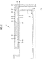
- the Saugwalzensystem comprises a hollow cylinder 2, which is at one of its ends 4, hereinafter referred to as "mounting end" 6, fixedly connected to a supporting structure, not shown.
- mounting end fixedly connected to a supporting structure, not shown.
- a drive motor 8 and a support flange 9 are mounted, on which the hollow cylinder 2 can be pushed.
- the interior 10 of the hollow cylinder 2 is connected via a provided at the end of assembly 6 implementation 11 to a in FIG. 1 by a vacuum pump 12 symbolized vacuum system 14 connected.
- the hollow cylinder 2 is pressure-tightly sealed by a cover 18, which may be designed as an independent component or may also be part of the casting body forming the hollow cylinder 2.
- the cylinder jacket 20 of the hollow cylinder 2 is interrupted by a number of control slots 22, via which the interior 10 of the hollow cylinder 2 is on the pressure side with its outer space in communication.
- the control slots 22 in this case have a circumferential direction the hollow cylinder 2 and the cylinder jacket 20 extending extension.
- the suction roll system comprises a distributor jacket 30, which is arranged within a cylindrical suction roll 32.
- the distributor shell 30 could be designed as an independent, inserted into the suction roll 32 and there suitably fastened component.
- the distributor jacket 30 is formed by the actual, suitably thickened and solid cylinder jacket 34 of the suction roll 32.
- the cylinder jacket 34 of the suction roll 32 is provided on its outer surface with a total of a perforation forming suction holes 36 through which the resting on the surface of the cylinder jacket 34 material can be sucked as needed.
- the suction roller 32 is closed at the end with a lid 38.
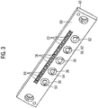
- the cylinder jacket 34 of the suction roll 32 is designed in several parts, wherein on its surface individual partial surfaces are designed as separate, removable components forming shell strips 40, each carrying a number of suction holes 36.
- the shell strips 40 are detachably connected via a respective suitable screw with the actual or "inner” Saugwalzenores forming cylinder jacket 34 and inserted for local positioning and lateral fixation in suitable grooves in the cylinder jacket 34.
- a jacket strip 40 can be embodied as a so-called suction strip, which is essentially provided with suction holes and, during the processing of cellulose tissue products, holds the respective section beginning of the tissue section.
- a shell strip 40 but also be designed as a so-called folding strip, which has a combination of suction holes and suction slots and the Function is fulfilled, which hold the cloth section during folding or folding, so that here forms after folding the new front edge of the cloth section.
- the suction roller 32 is pushed during assembly of the suction roller system on the hollow cylinder 2, so that in the assembled state of the Saugwalzensystems the hollow cylinder 2 projects into the suction roller 32 inside.
- the suction roll 32 is fastened at the assembly end 6 to a contact surface 43 driven by the drive motor 8.
- this contact surface 43 is set in rotation about the longitudinal axis of the suction roller system, so that with this, the suction roller 32 rotates correspondingly about its longitudinal axis.
- To support the suction roll 32 is mounted on a turn mounted on the hollow cylinder 2 sliding bearing ring 44.
- a substantially "flying bearing” of the suction roll 32 is realized, in which the essential bearing forces are taken over the end mounted slide bearing ring 44.
- a guide pin 45 can still be arranged at the free end of the carrier shaft 9, which engages in a corresponding inside centrally mounted in the lid 38, not shown in the figure recess.
- each distributor channel 46 opens below a respective associated folding strip 40 and is thus associated with the suction bores 36 arranged in the respective folding strip 40.
- Each distribution channel 46 thus provides in the mounted state, a gas or pressure side connection between the respective associated suction bores 36 of the suction roll 32 on the one hand and the interior of the cylinder jacket 34 on the other hand.
- the distribution channels 46 each have a widening from the inside to the outside cross section, wherein the distribution channels 46 on the outside of the distribution jacket 30 have a longitudinal direction of the suction roll 32 extending cross-section.
- the distribution channels 46 are dimensioned and dimensioned such that they are connected in the longitudinal direction - depending on the intended purpose - with one or more of the suction holes 36.
- the Saugwalzensystem thus forms a floating drum system, in which due to the above-described embodiment of the distribution channels 46, the vacuum and the ventilation is supplied to the suction holes 36 relative to the suction roller 32 in the radial direction.
- the individual rows of suction bores 36 for a product section, which extend across its width, are supplied by means of the distribution channels 46 via a channel system which is located below the product plane formed by the actual outer surface of the suction roll 32 in the distributor casing 30.
- the outside surface 50 of the distributor jacket 30 thus forms a second level of the channel guide.
- the inlet openings 52 can be placed variably, as seen in particular in the longitudinal direction of the suction roller 32, in the sense that their position is selected independently of the associated suction bores 36; the Vacuum or ventilation side provided connection between the respective inlet opening 52 and the associated suction bore 36 is achieved via a suitable channel guide of the distribution channels 46.
- the respective inlet opening 52 is arranged to match the associated control slot 22 in the inner, acting as a control body or control flange hollow cylinder 2.
- the respective control slot 22 is seen in the circumferential direction of the roller with respect to starting and end point and length suitably chosen and dimensioned to the desired timing for the associated suction holes 36.
- the respective control slot 22 is framed by a raised, bead-like framing which separates the vacuum region from the atmospheric vented region.
- the channel guide in particular the design of the distribution channels 46, a comparatively uniform, short channel cross-section and thus a favorable for rapid gas exchange length / cross-section ratio is achieved over all suction rows formed by the suction holes 36. This makes particularly fast charge changes and short switching times achievable, and in addition the useful and the dead volume are kept particularly low.
- the cylinder jacket 34 is still provided with a cleaning system.
- a cleaning system This is based on the concept of possibly removing adhering particles or material residues on the surface by means of compressed air.
- the hollow cylinder 2 is equipped with a channel for compressed air. On the output side, this opens into bores which are arranged in the bead-like boundary between the underpressure and the atmospheric region, so that compressed air can be applied to the supply duct in the rotating jacket.
- a two-sided surge can be applied to the center of the roller down.
- the pressure pulse can be automated, in particular synchronized with the system clock, or manually triggered.
- the Saugwalzensystem is also by a suitable Geoemetrie inches and design of the surface contour in the region of the suction holes 36 for a comparatively low vacuum level, ie a process pressure only comparatively little below atmospheric pressure executed.
- the gas exchange operations can be carried out with particularly short switching and reaction times.
- the exit region of the respective suction hole 36 suitable geometrically designed and contoured.
- suction holes 36 in the cylinder jacket 34 of the suction roll 32 ie, in the embodiment in the respective rabbet 40, which forms a partial surface of the outer surface 60 of the cylinder jacket 34 in the assembled state with a from the inner surface of the cylinder jacket 34 to Outer surface 60 of the cylinder jacket 34 toward flared cross-section.
- the suction holes 36 are designed in such a way that they have a cross-sectional contour at their outside end, at which a suction surface 62 at least partially has a height, ie with respect to their spacing the central axis of the suction roll 32, approximately in the outer surface 60 of the cylinder jacket 34 of the suction roll 32 positioned support surface 64 encloses.
- a geometry and contouring is formed, in which in the immediate vicinity of the respective suction surface 62 provided for supporting the material supporting surface 64 is positioned on the Material can rest properly to avoid deformations such as wrinkles.
Landscapes
- Engineering & Computer Science (AREA)
- Mechanical Engineering (AREA)
- Advancing Webs (AREA)
- Paper (AREA)
- Life Sciences & Earth Sciences (AREA)
- Forests & Forestry (AREA)
- Replacement Of Web Rolls (AREA)
- Perforating, Stamping-Out Or Severing By Means Other Than Cutting (AREA)
- Acyclic And Carbocyclic Compounds In Medicinal Compositions (AREA)
Priority Applications (2)
| Application Number | Priority Date | Filing Date | Title |
|---|---|---|---|
| RS20171342A RS56716B1 (sr) | 2012-11-13 | 2013-11-12 | Sistem sa usisnim valjkom |
| PL13798929T PL2919951T3 (pl) | 2012-11-13 | 2013-11-12 | Układ wałków ssących |
Applications Claiming Priority (2)
| Application Number | Priority Date | Filing Date | Title |
|---|---|---|---|
| DE102012022120.7A DE102012022120A1 (de) | 2012-11-13 | 2012-11-13 | Saugwalzensystem und Anlage zur Verarbeitung einer Materialbahn |
| PCT/EP2013/003405 WO2014075791A1 (de) | 2012-11-13 | 2013-11-12 | Saugwalzensystem |
Publications (2)
| Publication Number | Publication Date |
|---|---|
| EP2919951A1 EP2919951A1 (de) | 2015-09-23 |
| EP2919951B1 true EP2919951B1 (de) | 2017-10-04 |
Family
ID=49683665
Family Applications (1)
| Application Number | Title | Priority Date | Filing Date |
|---|---|---|---|
| EP13798929.9A Active EP2919951B1 (de) | 2012-11-13 | 2013-11-12 | Saugwalzensystem |
Country Status (11)
| Country | Link |
|---|---|
| EP (1) | EP2919951B1 (pt) |
| KR (1) | KR102163409B1 (pt) |
| CN (1) | CN104812539B (pt) |
| DE (1) | DE102012022120A1 (pt) |
| ES (1) | ES2654308T3 (pt) |
| HU (1) | HUE035742T2 (pt) |
| PL (1) | PL2919951T3 (pt) |
| PT (1) | PT2919951T (pt) |
| RS (1) | RS56716B1 (pt) |
| TW (1) | TWI553189B (pt) |
| WO (1) | WO2014075791A1 (pt) |
Families Citing this family (6)
| Publication number | Priority date | Publication date | Assignee | Title |
|---|---|---|---|---|
| DE102015224001A1 (de) * | 2015-12-02 | 2017-04-13 | Hueck Rheinische Gmbh | Presswalze mit Pressblech |
| CN109677978B (zh) * | 2019-01-07 | 2023-06-20 | 英穆自动化科技(厦门)有限公司 | 一种吸盘装置及其工作方法 |
| DE102019005949A1 (de) * | 2019-08-23 | 2021-02-25 | Texmag Gmbh Vertriebsgesellschaft | Walze zum Führen und/oder Breitstrecken einer laufenden Warenbahn |
| DE102019122784A1 (de) * | 2019-08-26 | 2021-03-04 | Voith Patent Gmbh | Former zur Herstellung einer Faserstoffbahn in einer Papiermaschine |
| JP7373464B2 (ja) * | 2020-06-05 | 2023-11-02 | リョービMhiグラフィックテクノロジー株式会社 | 真空吸引車 |
| CN111890466A (zh) * | 2020-08-24 | 2020-11-06 | 深圳市哈德胜精密科技股份有限公司 | 一种真空吸附装置和模切机 |
Family Cites Families (16)
| Publication number | Priority date | Publication date | Assignee | Title |
|---|---|---|---|---|
| DE2164554A1 (de) * | 1971-12-24 | 1973-06-28 | Jagenberg Werke Ag | Vorrichtung zum staubfreien laengsschneiden laufender werkstoffbahnen aus papier, karton, kunststoffolie od. dgl |
| FI82849C (fi) * | 1989-08-18 | 1991-04-25 | Valmet Paper Machinery Inc | Sugvals. |
| DE4000078A1 (de) * | 1990-01-03 | 1991-07-04 | Winkler Duennebier Kg Masch | Messerwalze |
| DD294676A5 (de) * | 1990-05-28 | 1991-10-10 | Planeta,Druckmaschinenwerk Ag,De | Saugwalze in auslagen von druckmaschinen |
| DE4405541C1 (de) * | 1994-02-22 | 1995-03-16 | Multigraf Ag | Vorrichtung zum Vereinzeln des obersten Bogens eines Stapels aus Blattmaterial |
| FI4537U1 (fi) * | 2000-03-31 | 2000-08-10 | Valmet Corp | Imutela |
| KR100419382B1 (ko) * | 2001-07-04 | 2004-02-19 | 주식회사 이페이퍼텍 | 다층기능지 제조방법 및 장치와 그 결과물 |
| CN2619968Y (zh) * | 2003-01-13 | 2004-06-09 | 谢文达 | 造纸脱水滚筒装置 |
| EP1473107A1 (en) * | 2003-05-02 | 2004-11-03 | Kba-Giori S.A. | Machine and process for cutting openings in a substrate |
| DE10336216A1 (de) * | 2003-08-07 | 2005-03-03 | Voith Paper Patent Gmbh | Dichtungseinrichtung für eine Papiermaschine |
| KR200334702Y1 (ko) * | 2003-09-01 | 2003-11-28 | 우순 테크놀로지 컴퍼니, 리미티드 | 흡입 노즐 캐리어 |
| SE528038C2 (sv) * | 2004-07-02 | 2006-08-15 | Sandvik Intellectual Property | En luftdistributionsaggregat och en rotationsknivanordning försedd med ett dylikt lutfdistributionsaggregat |
| CN201140551Y (zh) * | 2007-11-20 | 2008-10-29 | 熊猫电子集团有限公司 | 恒温吸辊 |
| DE102008042363B4 (de) * | 2008-09-25 | 2022-09-22 | Robert Bosch Gmbh | Verfahren zur Erzeugung eines Fahrzeug-Differenzmoments |
| DE102009033575B4 (de) | 2009-07-16 | 2011-07-21 | Winkler+Dünnebier AG, 56564 | Folienmesser mit Saugkammer |
| EP2697424B1 (en) * | 2011-04-15 | 2016-05-18 | Valmet Technologies, Inc. | A suction roll and a method of operating such a suction roll |
-
2012
- 2012-11-13 DE DE102012022120.7A patent/DE102012022120A1/de not_active Ceased
-
2013
- 2013-11-12 CN CN201380058739.1A patent/CN104812539B/zh active Active
- 2013-11-12 PT PT137989299T patent/PT2919951T/pt unknown
- 2013-11-12 WO PCT/EP2013/003405 patent/WO2014075791A1/de not_active Ceased
- 2013-11-12 KR KR1020157015307A patent/KR102163409B1/ko not_active Expired - Fee Related
- 2013-11-12 RS RS20171342A patent/RS56716B1/sr unknown
- 2013-11-12 ES ES13798929.9T patent/ES2654308T3/es active Active
- 2013-11-12 EP EP13798929.9A patent/EP2919951B1/de active Active
- 2013-11-12 PL PL13798929T patent/PL2919951T3/pl unknown
- 2013-11-12 TW TW102141048A patent/TWI553189B/zh active
- 2013-11-12 HU HUE13798929A patent/HUE035742T2/hu unknown
Non-Patent Citations (1)
| Title |
|---|
| None * |
Also Published As
| Publication number | Publication date |
|---|---|
| RS56716B1 (sr) | 2018-03-30 |
| CN104812539A (zh) | 2015-07-29 |
| PL2919951T3 (pl) | 2018-03-30 |
| DE102012022120A1 (de) | 2014-05-15 |
| KR20150086296A (ko) | 2015-07-27 |
| CN104812539B (zh) | 2018-05-01 |
| TWI553189B (zh) | 2016-10-11 |
| PT2919951T (pt) | 2018-01-03 |
| WO2014075791A1 (de) | 2014-05-22 |
| KR102163409B1 (ko) | 2020-10-08 |
| HUE035742T2 (hu) | 2018-05-28 |
| EP2919951A1 (de) | 2015-09-23 |
| TW201433674A (zh) | 2014-09-01 |
| ES2654308T3 (es) | 2018-02-13 |
Similar Documents
| Publication | Publication Date | Title |
|---|---|---|
| EP2919951B1 (de) | Saugwalzensystem | |
| DE4229699C2 (de) | Vorrichtung zur kontrollierten Beseitigung von Abfall-Stücken von Bedruckstoffen | |
| EP0553679B1 (de) | Einrichtung zur Entnahme von Probeexemplaren in einem Falzapparat | |
| EP1950140A2 (de) | Saugwalze zum Transportieren von Flachmaterialzuschnitten | |
| DE10346782A1 (de) | Bogentransporttrommel einer Bedruckstoffbogen verarbeitenden Maschine | |
| EP2214905B1 (de) | Zylinder einer druckmaschine mit mindestens einem unter dessen mantelfläche in dessen axialrichtung verlaufenden kanal | |
| EP0468254B1 (de) | Querschneider für mit Druckbildern versehene Materialbahnen | |
| DE102013108831A1 (de) | Rollenhandlingsystem mit einer einseitig lösbar befestigten Wickelwelle | |
| EP1837297B1 (de) | Vorrichtung zur Regelung des seitlichen Versatzes von Materialbahnen | |
| CH693985A5 (fr) | Vorrichtung und Verfahren zum Schneiden einer Materialbahn, insbesondere in einer Rotationsdruckmaschine. | |
| DE69400542T2 (de) | Papierschneidvorrichtung | |
| DE69513894T2 (de) | Aufnahmeeinrichtung für stabförmige Gegenstände | |
| EP1053965B1 (de) | Zylinderanordnung für einen Falzapparat einer Rotationsdruckmaschine | |
| EP1902854B2 (de) | Vorrichtung und Verfahren zur Druckweiterverarbeitung | |
| DE102006061316B4 (de) | Vorrichtung mit mehreren jeweils in einem Abstand zueinander angeordneten Speicherebenen | |
| AT501246A1 (de) | Querschneidvorrichtung und -verfahren für bahnmaterial | |
| EP1762529B1 (de) | Vorrichtung zur Bearbeitung bahnförmigen Materials | |
| EP1654097B1 (de) | Schneid-und transportwalze in einer wickelvorrichtung zum aufwickeln von materialbahnen | |
| DE102009060276A1 (de) | Vorrichtung zum Wenden von bahnförmigen Substraten | |
| DE19854053C2 (de) | Bogenführungseinrichtung für eine Druckmaschine | |
| EP1801053A2 (de) | Steuerkopf für eine Saugwalze | |
| EP2599395B1 (de) | Transporttrommel, ausgebildet und eingerichtet zum queraxialen Transport stabförmiger Artikel der Tabak verarbeitenden Industrie | |
| EP1348500A1 (de) | Vorrichtung zum intermittierenden Zuführen eines bandförmigen Rohlings | |
| EP2599396A2 (de) | Transporttrommel, ausgebildet und eingerichtet zum queraxialen Transport stabförmiger Artikel der Tabak verarbeitenden Industrie | |
| WO2013160402A1 (de) | Entnahmevorrichtung zur entnahme von flachteilen |
Legal Events
| Date | Code | Title | Description |
|---|---|---|---|
| PUAI | Public reference made under article 153(3) epc to a published international application that has entered the european phase |
Free format text: ORIGINAL CODE: 0009012 |
|
| 17P | Request for examination filed |
Effective date: 20150609 |
|
| AK | Designated contracting states |
Kind code of ref document: A1 Designated state(s): AL AT BE BG CH CY CZ DE DK EE ES FI FR GB GR HR HU IE IS IT LI LT LU LV MC MK MT NL NO PL PT RO RS SE SI SK SM TR |
|
| AX | Request for extension of the european patent |
Extension state: BA ME |
|
| DAX | Request for extension of the european patent (deleted) | ||
| 17Q | First examination report despatched |
Effective date: 20160727 |
|
| STAA | Information on the status of an ep patent application or granted ep patent |
Free format text: STATUS: EXAMINATION IS IN PROGRESS |
|
| REG | Reference to a national code |
Ref country code: DE Ref legal event code: R079 Ref document number: 502013008511 Country of ref document: DE Free format text: PREVIOUS MAIN CLASS: B26D0007180000 Ipc: B65H0020120000 |
|
| GRAP | Despatch of communication of intention to grant a patent |
Free format text: ORIGINAL CODE: EPIDOSNIGR1 |
|
| STAA | Information on the status of an ep patent application or granted ep patent |
Free format text: STATUS: GRANT OF PATENT IS INTENDED |
|
| RIC1 | Information provided on ipc code assigned before grant |
Ipc: D21F 3/10 20060101ALI20170531BHEP Ipc: B65H 5/22 20060101ALI20170531BHEP Ipc: B65H 27/00 20060101ALI20170531BHEP Ipc: B65H 29/24 20060101ALI20170531BHEP Ipc: B65H 20/12 20060101AFI20170531BHEP |
|
| INTG | Intention to grant announced |
Effective date: 20170619 |
|
| GRAS | Grant fee paid |
Free format text: ORIGINAL CODE: EPIDOSNIGR3 |
|
| GRAA | (expected) grant |
Free format text: ORIGINAL CODE: 0009210 |
|
| STAA | Information on the status of an ep patent application or granted ep patent |
Free format text: STATUS: THE PATENT HAS BEEN GRANTED |
|
| AK | Designated contracting states |
Kind code of ref document: B1 Designated state(s): AL AT BE BG CH CY CZ DE DK EE ES FI FR GB GR HR HU IE IS IT LI LT LU LV MC MK MT NL NO PL PT RO RS SE SI SK SM TR |
|
| REG | Reference to a national code |
Ref country code: GB Ref legal event code: FG4D Free format text: NOT ENGLISH |
|
| REG | Reference to a national code |
Ref country code: CH Ref legal event code: EP |
|
| REG | Reference to a national code |
Ref country code: AT Ref legal event code: REF Ref document number: 933803 Country of ref document: AT Kind code of ref document: T Effective date: 20171015 |
|
| REG | Reference to a national code |
Ref country code: IE Ref legal event code: FG4D Free format text: LANGUAGE OF EP DOCUMENT: GERMAN |
|
| REG | Reference to a national code |
Ref country code: DE Ref legal event code: R096 Ref document number: 502013008511 Country of ref document: DE |
|
| REG | Reference to a national code |
Ref country code: FR Ref legal event code: PLFP Year of fee payment: 5 |
|
| REG | Reference to a national code |
Ref country code: PT Ref legal event code: SC4A Ref document number: 2919951 Country of ref document: PT Date of ref document: 20180103 Kind code of ref document: T Free format text: AVAILABILITY OF NATIONAL TRANSLATION Effective date: 20171222 |
|
| REG | Reference to a national code |
Ref country code: NL Ref legal event code: MP Effective date: 20171004 |
|
| REG | Reference to a national code |
Ref country code: ES Ref legal event code: FG2A Ref document number: 2654308 Country of ref document: ES Kind code of ref document: T3 Effective date: 20180213 |
|
| REG | Reference to a national code |
Ref country code: LT Ref legal event code: MG4D |
|
| PG25 | Lapsed in a contracting state [announced via postgrant information from national office to epo] |
Ref country code: NL Free format text: LAPSE BECAUSE OF FAILURE TO SUBMIT A TRANSLATION OF THE DESCRIPTION OR TO PAY THE FEE WITHIN THE PRESCRIBED TIME-LIMIT Effective date: 20171004 |
|
| PG25 | Lapsed in a contracting state [announced via postgrant information from national office to epo] |
Ref country code: SE Free format text: LAPSE BECAUSE OF FAILURE TO SUBMIT A TRANSLATION OF THE DESCRIPTION OR TO PAY THE FEE WITHIN THE PRESCRIBED TIME-LIMIT Effective date: 20171004 Ref country code: FI Free format text: LAPSE BECAUSE OF FAILURE TO SUBMIT A TRANSLATION OF THE DESCRIPTION OR TO PAY THE FEE WITHIN THE PRESCRIBED TIME-LIMIT Effective date: 20171004 Ref country code: NO Free format text: LAPSE BECAUSE OF FAILURE TO SUBMIT A TRANSLATION OF THE DESCRIPTION OR TO PAY THE FEE WITHIN THE PRESCRIBED TIME-LIMIT Effective date: 20180104 Ref country code: LT Free format text: LAPSE BECAUSE OF FAILURE TO SUBMIT A TRANSLATION OF THE DESCRIPTION OR TO PAY THE FEE WITHIN THE PRESCRIBED TIME-LIMIT Effective date: 20171004 |
|
| REG | Reference to a national code |
Ref country code: HU Ref legal event code: AG4A Ref document number: E035742 Country of ref document: HU |
|
| PG25 | Lapsed in a contracting state [announced via postgrant information from national office to epo] |
Ref country code: HR Free format text: LAPSE BECAUSE OF FAILURE TO SUBMIT A TRANSLATION OF THE DESCRIPTION OR TO PAY THE FEE WITHIN THE PRESCRIBED TIME-LIMIT Effective date: 20171004 Ref country code: GR Free format text: LAPSE BECAUSE OF FAILURE TO SUBMIT A TRANSLATION OF THE DESCRIPTION OR TO PAY THE FEE WITHIN THE PRESCRIBED TIME-LIMIT Effective date: 20180105 Ref country code: BG Free format text: LAPSE BECAUSE OF FAILURE TO SUBMIT A TRANSLATION OF THE DESCRIPTION OR TO PAY THE FEE WITHIN THE PRESCRIBED TIME-LIMIT Effective date: 20180104 Ref country code: IS Free format text: LAPSE BECAUSE OF FAILURE TO SUBMIT A TRANSLATION OF THE DESCRIPTION OR TO PAY THE FEE WITHIN THE PRESCRIBED TIME-LIMIT Effective date: 20180204 Ref country code: LV Free format text: LAPSE BECAUSE OF FAILURE TO SUBMIT A TRANSLATION OF THE DESCRIPTION OR TO PAY THE FEE WITHIN THE PRESCRIBED TIME-LIMIT Effective date: 20171004 |
|
| REG | Reference to a national code |
Ref country code: SK Ref legal event code: T3 Ref document number: E 26718 Country of ref document: SK |
|
| REG | Reference to a national code |
Ref country code: DE Ref legal event code: R097 Ref document number: 502013008511 Country of ref document: DE |
|
| PG25 | Lapsed in a contracting state [announced via postgrant information from national office to epo] |
Ref country code: CZ Free format text: LAPSE BECAUSE OF FAILURE TO SUBMIT A TRANSLATION OF THE DESCRIPTION OR TO PAY THE FEE WITHIN THE PRESCRIBED TIME-LIMIT Effective date: 20171004 Ref country code: CH Free format text: LAPSE BECAUSE OF NON-PAYMENT OF DUE FEES Effective date: 20171130 Ref country code: LI Free format text: LAPSE BECAUSE OF NON-PAYMENT OF DUE FEES Effective date: 20171130 Ref country code: MC Free format text: LAPSE BECAUSE OF FAILURE TO SUBMIT A TRANSLATION OF THE DESCRIPTION OR TO PAY THE FEE WITHIN THE PRESCRIBED TIME-LIMIT Effective date: 20171004 Ref country code: EE Free format text: LAPSE BECAUSE OF FAILURE TO SUBMIT A TRANSLATION OF THE DESCRIPTION OR TO PAY THE FEE WITHIN THE PRESCRIBED TIME-LIMIT Effective date: 20171004 Ref country code: DK Free format text: LAPSE BECAUSE OF FAILURE TO SUBMIT A TRANSLATION OF THE DESCRIPTION OR TO PAY THE FEE WITHIN THE PRESCRIBED TIME-LIMIT Effective date: 20171004 |
|
| PLBE | No opposition filed within time limit |
Free format text: ORIGINAL CODE: 0009261 |
|
| STAA | Information on the status of an ep patent application or granted ep patent |
Free format text: STATUS: NO OPPOSITION FILED WITHIN TIME LIMIT |
|
| PG25 | Lapsed in a contracting state [announced via postgrant information from national office to epo] |
Ref country code: RO Free format text: LAPSE BECAUSE OF FAILURE TO SUBMIT A TRANSLATION OF THE DESCRIPTION OR TO PAY THE FEE WITHIN THE PRESCRIBED TIME-LIMIT Effective date: 20171004 Ref country code: LU Free format text: LAPSE BECAUSE OF NON-PAYMENT OF DUE FEES Effective date: 20171112 Ref country code: SM Free format text: LAPSE BECAUSE OF FAILURE TO SUBMIT A TRANSLATION OF THE DESCRIPTION OR TO PAY THE FEE WITHIN THE PRESCRIBED TIME-LIMIT Effective date: 20171004 |
|
| REG | Reference to a national code |
Ref country code: BE Ref legal event code: MM Effective date: 20171130 |
|
| REG | Reference to a national code |
Ref country code: IE Ref legal event code: MM4A |
|
| 26N | No opposition filed |
Effective date: 20180705 |
|
| PG25 | Lapsed in a contracting state [announced via postgrant information from national office to epo] |
Ref country code: MT Free format text: LAPSE BECAUSE OF FAILURE TO SUBMIT A TRANSLATION OF THE DESCRIPTION OR TO PAY THE FEE WITHIN THE PRESCRIBED TIME-LIMIT Effective date: 20171004 |
|
| PG25 | Lapsed in a contracting state [announced via postgrant information from national office to epo] |
Ref country code: IE Free format text: LAPSE BECAUSE OF NON-PAYMENT OF DUE FEES Effective date: 20171112 |
|
| PG25 | Lapsed in a contracting state [announced via postgrant information from national office to epo] |
Ref country code: SI Free format text: LAPSE BECAUSE OF FAILURE TO SUBMIT A TRANSLATION OF THE DESCRIPTION OR TO PAY THE FEE WITHIN THE PRESCRIBED TIME-LIMIT Effective date: 20171004 Ref country code: BE Free format text: LAPSE BECAUSE OF NON-PAYMENT OF DUE FEES Effective date: 20171130 |
|
| PG25 | Lapsed in a contracting state [announced via postgrant information from national office to epo] |
Ref country code: CY Free format text: LAPSE BECAUSE OF FAILURE TO SUBMIT A TRANSLATION OF THE DESCRIPTION OR TO PAY THE FEE WITHIN THE PRESCRIBED TIME-LIMIT Effective date: 20171004 |
|
| PG25 | Lapsed in a contracting state [announced via postgrant information from national office to epo] |
Ref country code: MK Free format text: LAPSE BECAUSE OF FAILURE TO SUBMIT A TRANSLATION OF THE DESCRIPTION OR TO PAY THE FEE WITHIN THE PRESCRIBED TIME-LIMIT Effective date: 20171004 |
|
| REG | Reference to a national code |
Ref country code: AT Ref legal event code: MM01 Ref document number: 933803 Country of ref document: AT Kind code of ref document: T Effective date: 20181112 |
|
| PG25 | Lapsed in a contracting state [announced via postgrant information from national office to epo] |
Ref country code: AT Free format text: LAPSE BECAUSE OF NON-PAYMENT OF DUE FEES Effective date: 20181112 |
|
| PG25 | Lapsed in a contracting state [announced via postgrant information from national office to epo] |
Ref country code: AL Free format text: LAPSE BECAUSE OF FAILURE TO SUBMIT A TRANSLATION OF THE DESCRIPTION OR TO PAY THE FEE WITHIN THE PRESCRIBED TIME-LIMIT Effective date: 20171004 |
|
| PGFP | Annual fee paid to national office [announced via postgrant information from national office to epo] |
Ref country code: HU Payment date: 20201108 Year of fee payment: 8 Ref country code: PT Payment date: 20201029 Year of fee payment: 8 Ref country code: GB Payment date: 20201123 Year of fee payment: 8 |
|
| PGFP | Annual fee paid to national office [announced via postgrant information from national office to epo] |
Ref country code: SK Payment date: 20201029 Year of fee payment: 8 |
|
| REG | Reference to a national code |
Ref country code: SK Ref legal event code: MM4A Ref document number: E 26718 Country of ref document: SK Effective date: 20211112 |
|
| GBPC | Gb: european patent ceased through non-payment of renewal fee |
Effective date: 20211112 |
|
| PG25 | Lapsed in a contracting state [announced via postgrant information from national office to epo] |
Ref country code: SK Free format text: LAPSE BECAUSE OF NON-PAYMENT OF DUE FEES Effective date: 20211112 Ref country code: PT Free format text: LAPSE BECAUSE OF NON-PAYMENT OF DUE FEES Effective date: 20220512 Ref country code: HU Free format text: LAPSE BECAUSE OF NON-PAYMENT OF DUE FEES Effective date: 20211113 |
|
| PG25 | Lapsed in a contracting state [announced via postgrant information from national office to epo] |
Ref country code: GB Free format text: LAPSE BECAUSE OF NON-PAYMENT OF DUE FEES Effective date: 20211112 |
|
| P01 | Opt-out of the competence of the unified patent court (upc) registered |
Effective date: 20230527 |
|
| PGFP | Annual fee paid to national office [announced via postgrant information from national office to epo] |
Ref country code: PL Payment date: 20241030 Year of fee payment: 12 |
|
| PGFP | Annual fee paid to national office [announced via postgrant information from national office to epo] |
Ref country code: FR Payment date: 20241121 Year of fee payment: 12 |
|
| PGFP | Annual fee paid to national office [announced via postgrant information from national office to epo] |
Ref country code: ES Payment date: 20241213 Year of fee payment: 12 |
|
| PGFP | Annual fee paid to national office [announced via postgrant information from national office to epo] |
Ref country code: TR Payment date: 20241101 Year of fee payment: 12 |
|
| PGFP | Annual fee paid to national office [announced via postgrant information from national office to epo] |
Ref country code: DE Payment date: 20251124 Year of fee payment: 13 |
|
| PGFP | Annual fee paid to national office [announced via postgrant information from national office to epo] |
Ref country code: IT Payment date: 20251128 Year of fee payment: 13 |
|
| PGFP | Annual fee paid to national office [announced via postgrant information from national office to epo] |
Ref country code: RS Payment date: 20251107 Year of fee payment: 13 |