EP2919980B1 - Vorrichtung und verfahren zur montage der gürtellage eines reifens - Google Patents
Vorrichtung und verfahren zur montage der gürtellage eines reifens Download PDFInfo
- Publication number
- EP2919980B1 EP2919980B1 EP13789338.4A EP13789338A EP2919980B1 EP 2919980 B1 EP2919980 B1 EP 2919980B1 EP 13789338 A EP13789338 A EP 13789338A EP 2919980 B1 EP2919980 B1 EP 2919980B1
- Authority
- EP
- European Patent Office
- Prior art keywords
- rollers
- axis
- assembly device
- rotation
- circumference
- Prior art date
- Legal status (The legal status is an assumption and is not a legal conclusion. Google has not performed a legal analysis and makes no representation as to the accuracy of the status listed.)
- Active
Links
- 238000000034 method Methods 0.000 title claims description 14
- 239000011324 bead Substances 0.000 claims description 12
- 238000004519 manufacturing process Methods 0.000 claims description 7
- 238000007493 shaping process Methods 0.000 claims description 6
- 239000012528 membrane Substances 0.000 description 10
- 230000002787 reinforcement Effects 0.000 description 6
- 230000003014 reinforcing effect Effects 0.000 description 6
- 238000000605 extraction Methods 0.000 description 4
- 238000013519 translation Methods 0.000 description 4
- 238000004804 winding Methods 0.000 description 4
- 241001417494 Sciaenidae Species 0.000 description 2
- 238000010276 construction Methods 0.000 description 2
- 230000000694 effects Effects 0.000 description 2
- 230000001012 protector Effects 0.000 description 2
- 241000287107 Passer Species 0.000 description 1
- 230000015572 biosynthetic process Effects 0.000 description 1
- 230000006835 compression Effects 0.000 description 1
- 238000007906 compression Methods 0.000 description 1
- 238000000151 deposition Methods 0.000 description 1
- 238000009434 installation Methods 0.000 description 1
- 239000002184 metal Substances 0.000 description 1
- 239000000203 mixture Substances 0.000 description 1
- 238000012986 modification Methods 0.000 description 1
- 230000004048 modification Effects 0.000 description 1
- 238000011017 operating method Methods 0.000 description 1
- 238000007789 sealing Methods 0.000 description 1
- 239000004753 textile Substances 0.000 description 1
- 238000012549 training Methods 0.000 description 1
- 238000004073 vulcanization Methods 0.000 description 1
Images


Classifications
-
- B—PERFORMING OPERATIONS; TRANSPORTING
- B29—WORKING OF PLASTICS; WORKING OF SUBSTANCES IN A PLASTIC STATE IN GENERAL
- B29D—PRODUCING PARTICULAR ARTICLES FROM PLASTICS OR FROM SUBSTANCES IN A PLASTIC STATE
- B29D30/00—Producing pneumatic or solid tyres or parts thereof
- B29D30/06—Pneumatic tyres or parts thereof (e.g. produced by casting, moulding, compression moulding, injection moulding, centrifugal casting)
- B29D30/08—Building tyres
- B29D30/10—Building tyres on round cores, i.e. the shape of the core is approximately identical with the shape of the completed tyre
- B29D30/14—Rolling-down or pressing-down the layers in the building process
-
- B—PERFORMING OPERATIONS; TRANSPORTING
- B29—WORKING OF PLASTICS; WORKING OF SUBSTANCES IN A PLASTIC STATE IN GENERAL
- B29D—PRODUCING PARTICULAR ARTICLES FROM PLASTICS OR FROM SUBSTANCES IN A PLASTIC STATE
- B29D30/00—Producing pneumatic or solid tyres or parts thereof
- B29D30/06—Pneumatic tyres or parts thereof (e.g. produced by casting, moulding, compression moulding, injection moulding, centrifugal casting)
- B29D30/08—Building tyres
- B29D30/10—Building tyres on round cores, i.e. the shape of the core is approximately identical with the shape of the completed tyre
- B29D30/16—Applying the layers; Guiding or stretching the layers during application
- B29D30/1621—Applying the layers; Guiding or stretching the layers during application by feeding a continuous band and winding it spirally, i.e. the band is fed without relative movement along the core axis, to form an annular element
-
- B—PERFORMING OPERATIONS; TRANSPORTING
- B29—WORKING OF PLASTICS; WORKING OF SUBSTANCES IN A PLASTIC STATE IN GENERAL
- B29D—PRODUCING PARTICULAR ARTICLES FROM PLASTICS OR FROM SUBSTANCES IN A PLASTIC STATE
- B29D30/00—Producing pneumatic or solid tyres or parts thereof
- B29D30/06—Pneumatic tyres or parts thereof (e.g. produced by casting, moulding, compression moulding, injection moulding, centrifugal casting)
- B29D30/08—Building tyres
- B29D30/10—Building tyres on round cores, i.e. the shape of the core is approximately identical with the shape of the completed tyre
- B29D30/16—Applying the layers; Guiding or stretching the layers during application
- B29D30/1628—Applying the layers; Guiding or stretching the layers during application by feeding a continuous band and winding it helically, i.e. the band is fed while being advanced along the core axis, to form an annular element
-
- B—PERFORMING OPERATIONS; TRANSPORTING
- B29—WORKING OF PLASTICS; WORKING OF SUBSTANCES IN A PLASTIC STATE IN GENERAL
- B29D—PRODUCING PARTICULAR ARTICLES FROM PLASTICS OR FROM SUBSTANCES IN A PLASTIC STATE
- B29D30/00—Producing pneumatic or solid tyres or parts thereof
- B29D30/06—Pneumatic tyres or parts thereof (e.g. produced by casting, moulding, compression moulding, injection moulding, centrifugal casting)
- B29D30/08—Building tyres
- B29D30/20—Building tyres by the flat-tyre method, i.e. building on cylindrical drums
- B29D30/28—Rolling-down or pressing-down the layers in the building process
-
- B—PERFORMING OPERATIONS; TRANSPORTING
- B29—WORKING OF PLASTICS; WORKING OF SUBSTANCES IN A PLASTIC STATE IN GENERAL
- B29D—PRODUCING PARTICULAR ARTICLES FROM PLASTICS OR FROM SUBSTANCES IN A PLASTIC STATE
- B29D30/00—Producing pneumatic or solid tyres or parts thereof
- B29D30/06—Pneumatic tyres or parts thereof (e.g. produced by casting, moulding, compression moulding, injection moulding, centrifugal casting)
- B29D30/08—Building tyres
- B29D30/10—Building tyres on round cores, i.e. the shape of the core is approximately identical with the shape of the completed tyre
- B29D30/16—Applying the layers; Guiding or stretching the layers during application
- B29D2030/1664—Details, accessories or auxiliary operations not provided for in the other subgroups of B29D30/00
- B29D2030/1678—Details, accessories or auxiliary operations not provided for in the other subgroups of B29D30/00 the layers being applied being substantially continuous, i.e. not being cut before the application step
-
- B—PERFORMING OPERATIONS; TRANSPORTING
- B29—WORKING OF PLASTICS; WORKING OF SUBSTANCES IN A PLASTIC STATE IN GENERAL
- B29D—PRODUCING PARTICULAR ARTICLES FROM PLASTICS OR FROM SUBSTANCES IN A PLASTIC STATE
- B29D30/00—Producing pneumatic or solid tyres or parts thereof
- B29D30/06—Pneumatic tyres or parts thereof (e.g. produced by casting, moulding, compression moulding, injection moulding, centrifugal casting)
- B29D30/08—Building tyres
- B29D30/20—Building tyres by the flat-tyre method, i.e. building on cylindrical drums
- B29D30/30—Applying the layers; Guiding or stretching the layers during application
- B29D2030/3064—Details, accessories and auxiliary operations not otherwise provided for
- B29D2030/3078—Details, accessories and auxiliary operations not otherwise provided for the layers being applied being substantially continuous, i.e. not being cut before the application step
Definitions
- the invention relates to the field of tire manufacturing and is more particularly concerned with the step of assembling the crown belt on a carcass of the tire.
- This assembly step is preceded, as a rule, by a shaping step which consists of passing the tire blank whose shape is substantially cylindrical to a generally toroidal shape.
- the most traditional method is to place the carcass on a device comprising two rims adapted to receive the beads of the blank, and between which is mounted a flexible conformation membrane.
- An alternative is to use rims forming a tight connection with the beads of the blank.
- the tire blank is conformed by inflating the interior space of the membrane or the blank, and by axially bringing the two rims together with the beads (see FIG. JP 2001 277377 and DE 199 42 220 A1 ).
- the present description is particularly directed to this type of device and conformation method.
- the shaped blank is the result of this conformation operation.
- the shape of the torus obtained depends on the natural balance curve resulting from the setting in tension, under the effect of the pressure prevailing in the membrane or in the interior space of the shaped blank, carcass reinforcement plies anchored by their axial ends on each of the beads.
- the natural shape of the outer surface of the shaped blank intended to receive the crown belt is generally very curved.
- the construction of the crown of the tire blank can be continued by successively depositing the crown reinforcement plies, the shrinking ply and the tread directly on the shaped blank obtained after inflation of the membrane.
- this operating mode does not make it possible to produce tires for which shape of the top differs from the natural shape of the conformation membrane when inflated. This is the case for most modern tires in which the flank heights are reduced with respect to the width of the vertex and whose crown curve passes radially very much inside the natural equilibrium curve.
- a first known alternative then consists in clamping the extension of the central part of the conformation membrane with the aid of plies integrated in its top, so as to obtain the desired profile. But this method is hampered by the lack of control of the inflation diameter and therefore the laying diameter of the components forming the top belt. Shaping means using rigid supports are also used, but do not allow very high conformation rates because of the radii of curvature imposed by the rigid support elements.
- the alternative method of making the crown reinforcement belt on a separate means has been widely developed in the industry.
- the construction of the top is performed by winding the aforementioned components on a substantially cylindrical shape whose curve is adapted to the shape of the top of the envelope. Then, using for example a vacuum ferrule, it comes to grasp the crown belt by its outer circumference, the carcass is introduced into the ring thus formed, and the conformation membrane is inflated so that, in increasing its diameter, the carcass comes into close contact with the inner circumference of the vertex belt.
- the blank, capped with its top, is then routed to the vulcanization workshop.
- the invention aims to provide an alternative device and method for assembling the crown belt on the shaped carcass, while ensuring a profile of the components forming said belt that meets the requirements of modern tires.
- the assembly device intended for the manufacture of a tire blank comprises holding means capable of containing a tire carcass formed by the radially outer wall of its top according to a given circumference and placed in position. rotation around its axis.
- This device is characterized in that said holding means comprise an introduction window enabling passing linear components between the radially outer surface of said vertex and the radially inner portion of said holding means.
- the shaped blank is then contained at a given circumference, perfectly controllable, and less than the circumference obtained when the shaped carcass conforms to its natural profile after conformation.
- the laying of the components forming the crown belt is carried out simply by causing said components to enter the introduction window and by rotating the blank about its axis of rotation.
- the holding means are formed by a plurality of rollers whose axis of rotation is oriented in the direction of the axis of the drum, said rollers being radially movable and arranged so as to form a space circular interior of given circumference.
- said rollers are rotatably mounted by only one of their axial end on a plate, so as to allow the introduction and extraction of the tire blank.
- the rollers have a concave meridian profile adapted to the profile of the crown of the tire blank to be produced.
- the introduction window is defined by the space between two rollers.
- At least one of the rollers is a motorized roller.
- one will choose to motorize one of the two rollers defining the introduction window, or both, or even all of the rollers so as to facilitate the formation of the blank in rotation.
- one of the two rollers defining the introduction window is a master roll.
- the holding means are formed by a band, held by two rollers oriented in the direction of the axis of rotation of the blank ', and between which said band is adapted to circulating around the circumference of the top of the shaped tire blank rotated about said axis.
- the spacing between the two rollers defines the introduction window.
- the position of the two rollers defining the introduction window on the plate is adjustable in two directions perpendicular to the axis of rotation of the blank, and preferably perpendicular to each other, so as to allow on the one hand the introduction and extraction of the tire blank and secondly adjustment of the diameter with respect to the axis of rotation of the blank of the portion of the band surrounding the tire blank
- said two rollers defining the introduction window are rotatably mounted by only one of their axial end on a plate.
- At least one of the two rollers defining the introduction window is motorized so as to facilitate the driving of the components in the introduction window.
- the band is encircled around rollers arranged outside the space occupied by the band when said band is in contact with the external surface of the tire blank, so as to form a closed loop.
- the tape assembly device comprises means capable of modifying the length and the tension of the portion of the strip intended to contain the tire blank at its top and flowing between the two rollers defining the introduction window.
- this method may provide for modifying the radially inner circumference of the holding means after the laying of each of the components, so as to maintain the radially outer surface of the tire blank at the initial circumference.
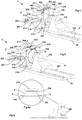
- the figure 1 represents a device 1 according to a first embodiment of the invention.
- This device comprises a plate 100 mounted on rails 151 fixed on a frame 10, and on which are mounted a plurality of rollers 110, 111, 120.
- the rollers 110, 111, 120 are arranged in a cylinder of axis XX '.
- the reference axis XX ' is parallel to the rails 151.
- the axes of rotation of the rollers are also parallel to the axis XX'.
- Each of the rollers is rotatably attached by one of its axial ends to a support 102 sliding on a rail 101 oriented radially with respect to the axis XX '.
- a mechanism (not shown) makes it possible to bring the set of rollers of the axis XX 'closer together or at the same time.
- the set of radially internal generatrices of each of the rollers defines an interior space which limits the extension of the crown of the tire blank during the conformation.
- the reference axis XX ' is therefore also the axis of rotation of the blank.
- the space between the two rollers 110 and 111 forms an introduction window F constituting the passage through which are introduced the components for forming the crown reinforcement belt.
- These components can be formed by profiles, rubber bands, or by reinforcing elements, for example textile or metal reinforcing threads, embedded in a rubber mixture and at a given angle with the longitudinal direction of the component to be wound. .
- the rollers may be free to rotate but also include motorization means for improving the drive of the tire blank during the introduction of the linear components. Also, it will preferably be chosen to motorize the rollers defining the introduction window to ensure good training components in the introduction window.
- a frame 150 is mounted on the rails 151, so that said frame 150 is movable in translation in the direction XX 'relative to the plate 100 supporting the rollers.
- the frame 150 supports a drum 140 rotated about the reference axis XX 'by a motor (not shown).
- the drum 140 comprises two rims 141 and 142 (see medallion 3a of the figure 3 ) movable in translation relative to each other in the direction XX ', and intended to receive the beads b 1 and b 2 of the blank E tire, as shown on the Figures 2 and 3 .
- the rims may be of the type forming a tight connection with the beads b 1 and b 2 or standard non-sealed type. In the latter case, it will be necessary to provide a shaping membrane 160 (reference visible on the figure 1 ) forming a connection sealed with the rims as was explained in the previous paragraphs.
- Means make it possible to introduce air under pressure into the interior space formed by the tire blank or by the conformation membrane.
- the figure 3 represents the device according to this first embodiment when the tire blank has just been shaped.
- the rollers 120 press on the top of the blank and prevent it from adopting the natural profile that the blank would have in the absence of these rollers.
- the surface of the crown is therefore contained in the interior space formed by the radially internal generatrices of the plurality of rollers on which it bears under the effect of the internal air pressure.
- rollers 120 are important, and provided that they are distributed as regularly as possible around the circumference of the blank, the more the points of contact between the rollers and the top of the blank conformed are brought together and distributed throughout the circumference. This results in better control of the circumference of the products forming the reinforcing belt.
- the proximity between two successive rollers also makes it possible to contain the natural expansion of the shaped blank and thus of the laying surface to the curved shape that it would have without the presence of said rollers.
- the operating procedure for a device of the type described above provides for producing a tire carcass of generally cylindrical shape and comprising reinforcing rings of beads around which are anchored the two axial ends of the reinforcing ply of carcass, a sealing ply located radially under the carcass reinforcement ply, as well as sections intended to protect the carcass such as bead protectors or sidewall protectors.
- the carcass can be made on separate assembly means or directly on the drum 140.
- the carcass, held by the rims 141 and 142, is then axially approached along the axis XX 'of the holding means formed by the plurality of rollers, which will have been previously arranged in their initial position on a circumference of a given radius.
- the conformation of the carcass is then initiated by putting under pressure the internal space between the rims and the carcass and bringing the two rims axially together until the shaped carcass comes to bear against the radially internal generatrices of the rollers 120.
- the profile of the crown surface of the shaped carcass is given by the transverse profile of the plurality of rollers. It is thus possible to use rollers of cylindrical shape with rectilinear generatrices for obtaining a top of the blank of flat shape as illustrated in the medallion 3a of the figure 3 . It is also possible to impart a concave shape to said generatrices of each of the rollers in order to obtain a peak of slightly convex shaped blank as illustrated by the roller 120 b in the medallion 3b of the figure 3 .
- the circumference of the laying surface after conformation of the bare blank is considered as the base circumference whose diameter substantially corresponds to the inside diameter of the circumference axis XX 'not register the radially internal generatrices of the rollers 120 in their initial position.
- the surface of the blank at this stage of assembly is considered the base surface.
- the laying of the components forming the crown belt can then be performed by introducing the components as the product P 2 by the window F formed by the space between the rollers 110 and 111, and rotating about its axis XX ' the shaped blank supported by the rims 141 and 142, as illustrated in FIG. figure 7 .
- the shaped blank then rolls inside the rollers 120, and the top of the blank maintains the profile imposed by the rollers.
- the method according to the invention provides for modifying the radial position of the rollers to increase at will the circumference indicated by the rollers at the points of contact with the blank, so as to maintain the base circumference of the base surface at a minimum. constant value.
- the rollers 110, 111 and 120 are displaced radially outwards.
- the rollers can also be moved as and as the winding of thick components, such as the tread, to prevent compression or radial deformation of the surface of based.
- rollers 110, 111 and 120 are then spaced so as to release the blank and to allow its shipment to the next step of manufacture.
- the device 2 represented in the Figures 4, 5 and 6 represents an alternative form of implementation of the invention, in which the holding means are constituted by a flexible and continuous band 230, forming a closed loop, and circulating between a set of rollers 210, 211, 212, 213, 214 , 215, 216, 217 (visible only on the figure 9 ) and 218.
- the axes of rotation of the rollers are parallel to each other and to the axis XX '.
- the rollers 210 and 211 are rotatably mounted by one of their axial end on supports 204 and 205 circulating on a rail 206 fixed to a frame 203.
- the frame 203 is mounted on a plate 200 by means of motorized elements (not visible) moving in lights 201 and 202 disposed on the plate 200 and oriented in a direction perpendicular to the direction of the rail 206.
- At least one of the two rollers is motorized, preferably both are motorized.
- one "master" roll and the other a "slave” roll.
- Conventionally in the field of automation when speaking of a "master” actuator, reference is made to the regulation of the assembly process, that is to say of all the actuators. If the roll is master, this means that its angular position serves as a reference for the control of the process with regard to other actuators that are called “slaves”.
- rollers 210, 211 of the device 2 if they are motorized, facilitate the driving of the components in the introduction window.
- the plane of the plate 200 is perpendicular to the axis XX '.
- the portion of the band forming a loop, and between the rollers 210 and 211, is intended to contain the shaped blank E by the radially outer surface of its top, as shown in FIG. figure 2 .
- rollers 212, 213, 216, 217 and 218 make it possible to circulate the strip in a closed circuit around the space intended to receive the shaped blank. These rolls are rotatably mounted by one of their axial end directly on the plate 200.
- a roller 214 rotatably mounted at one of its axial ends on a support 207 runs on a rail 208 fixed to the plate 200. In this way, by modifying the position of the support 207, the length of the loop formed by the between the rollers 210 and 211. And when the shaped blank E is in position, it is also possible to adjust the tightening tension of the band around the surface of the top of said blank.
- the spacing between the rollers 210 and 211 defines the introduction window F.
- the plate 200 is mounted on rails 251, parallel to the axis XX 'and fixed on a frame 20.
- a frame 250 is mounted on the rails 251, so that said frame 250 is movable in translation in the direction of the axis XX 'relative to the plate 200 supporting the rollers and the retaining band 230.
- the frame 250 supports a drum 240 driven in rotation about the axis XX 'by a motor (not shown).
- the drum 240 comprises two rims 241 and 242 (see medallion 6a of the figure 6 ) movable in translation towards each other in the direction of the axis XX ', and intended to receive the beads b 1 and b 2 of the tire blank E, as shown in FIG. figure 6 .
- the rims 241 and 242 may also be of the type forming a tight connection with the beads b 1 and b 2 or of the standard type. Means also make it possible to introduce air under pressure into the interior space formed by the tire blank or by the conformation membrane.
- the figure 6 represents the device according to this second embodiment when the tire blank has just been shaped.
- the base surface of the blank comes into contact with the rollers 210 and 211 on the one hand and with the band 230 on the other hand.
- the length of the loop formed by the band between the two rollers 210 and 211 makes it possible to control the clamping circumference of the tire blank at base circumference desired.
- the band thus acts in a manner similar to the multiplicity of rolls described above, depriving the blank of the possibility of adopting its natural profile.
- the introduction and extraction of the tire blank is done by separating or moving the rollers along the rail 206, taking care to maintain a minimum spacing between said rollers to clear enough space to introduce the components between the band and the radially outer surface of the shaped blank.
- FIGS. Figures 8 and 9 The introduction of the components constituting the vertex belt through the introduction window F is illustrated in FIGS. Figures 8 and 9 .
- the circumference of the band surrounding the shaped blank can be modified as desired during the introduction of each of the sections so as to maintain a constant value.
- the basic circumference of the base surface of the blank E it is also possible to modify the radial position of the rollers 210 and 211 so as to maintain the center of the circumference formed by the band circulating around the shaped blank on the axis XX '.
Landscapes
- Engineering & Computer Science (AREA)
- Mechanical Engineering (AREA)
- Tyre Moulding (AREA)
Claims (16)
- Montagevorrichtung, welche zur Herstellung eines Reifenrohlings bestimmt ist, wobei die Montagevorrichtung Haltemittel (110, 111, 120, 210, 211, 230) umfasst, wobei die Haltemittel geeignet sind, eine geformte Reifenkarkasse (E) entlang einer radial äußeren Fläche des Scheitels der Karkasse zu begrenzen, wobei die Karkasse entlang eines gegebenen Umfangs begrenzt wird und in Rotation um eine Drehachse XX' versetzt wird, dadurch gekennzeichnet, dass die Haltemittel ein Einführfenster (F) umfassen, welches ermöglicht, lineare Komponenten zwischen der radial äußeren Fläche des Scheitels und einem radial inneren Teil der Haltemittel durchlaufen zu lassen.
- Montagevorrichtung nach Anspruch 1, welche außerdem umfasst:- ein Gestell (150, 250), das eine Montagetrommel (140, 240) trägt, wobei die Trommel Felgen (141, 142, 241, 242) umfasst, die mit der Drehachse XX' koaxial sind und dafür eingerichtet sind, die Wülste (b1, b2) des Reifenrohlings aufzunehmen,- Mittel zum Formen des Reifenrohlings,- Mittel zum Versetzen der Montagetrommel (140, 240) in Rotation um die Achse XX'.
- Montagevorrichtung nach Anspruch 1 oder 2, wobei die Haltemittel (110, 111, 120) von einer Vielzahl von Walzen gebildet werden, deren Drehachse in der Richtung der Achse XX' ausgerichtet ist, wobei die Walzen bezüglich der Achse XX' radial beweglich sind und derart angeordnet sind, dass sie einen kreisförmigen inneren Raum mit gegebenem Umfang bilden.
- Montagevorrichtung nach Anspruch 3, wobei die Walzen (110, 111, 120) an nur einem ihrer axialen Enden an einer Platte (100) drehbar gelagert sind.
- Montagevorrichtung nach einem der Ansprüche 3 oder 4, wobei die Walzen (120b) ein konkaves Meridianprofil aufweisen, das an das Profil des Scheitels des herzustellenden Reifenrohlings angepasst ist.
- Vorrichtung nach einem der Ansprüche 3 bis 5, wobei das Einführfenster F durch den Zwischenraum zwischen zwei Walzen (110, 111) definiert ist.
- Montagevorrichtung nach einem der Ansprüche 3 bis 6, wobei wenigstens eine der Walzen (110, 11, 120) motorisch angetrieben ist.
- Montagevorrichtung nach Anspruch 1 oder 2, wobei die Haltemittel von einem Band (230) gebildet werden, das von zwei Walzen (210, 211) gehalten wird, die in der Richtung der Achse XX' ausgerichtet sind und zwischen denen das Band (230) um den Umfang des Scheitels des geformten Reifenrohlings (E) herum, welcher in Drehung um die Achse XX' versetzt wird, in der Lage ist umzulaufen.
- Montagevorrichtung nach Anspruch 8, wobei der Zwischenraum zwischen den zwei Walzen (210, 211) das Einführfenster F definiert.
- Vorrichtung nach einem der Ansprüche 8 oder 9, wobei die Position der Walzen in zwei Richtungen verstellbar ist, die zu der Achse XX' senkrecht und vorzugsweise zueinander senkrecht sind.
- Montagevorrichtung nach Anspruch 10, wobei die Walzen (210, 211) an nur einem ihrer axialen Enden an einer Platte (200) drehbar gelagert sind.
- Montagevorrichtung nach einem der Ansprüche 10 oder 11, wobei wenigstens eine der Walzen (210, 211) motorisch angetrieben ist.
- Montagevorrichtung nach einem der Ansprüche 8 bis 12, wobei das endlose Band (230) um Walzen (212, 213, 214, 215, 216, 217, 218) umläuft, die außerhalb des von dem endlosen Band eingenommenen Raumes angeordnet sind, wenn sich das Band in Kontakt mit der Außenfläche des Reifenrohlings befindet, so dass es eine geschlossene Schleife bildet.
- Vorrichtung nach Montage nach einem der Ansprüche 8 bis 13, welche ein Mittel (214, 208) umfasst, das geeignet ist, die Länge und die Spannung des Teils des Bandes (230) zu ändern, der zwischen den zwei Walzen (210, 211) umläuft und dazu bestimmt ist, den Reifenrohling an seinem Scheitel zu begrenzen.
- Verfahren zur Montage eines Reifenrohlings, welches Schritte umfasst, in welchen:- der Rohling einer Reifenkarkasse hergestellt wird,- mithilfe einer Vorrichtung nach einem der Ansprüche 1 bis 14, deren radial innerer Umfang zuvor auf einen vorbestimmten Anfangswert eingestellt wurde, die Karkasse geformt wird, um ihr eine im Wesentlichen torusförmige Gestalt zu verleihen, derart, dass eine Grundfläche des geformten Rohlings E, die dazu bestimmt ist, den Scheitelgürtel aufzunehmen, an einem anfänglichen Umfang begrenzt wird, der durch die Haltemittel gegeben ist,- der Rohling in Rotation um seine Achse XX' versetzt wird und auf der radial äußeren Fläche des Rohlings die linearen Komponenten aufgebracht werden, die den Scheitelgürtel des Reifens bilden, indem sie durch das Einführfenster F durchlaufen gelassen werden.
- Verfahren nach Anspruch 15, wobei der radial innere Umfang der Haltemittel nach der Anbringung jeder der Komponenten geändert wird, derart, dass für die Grundfläche des Rohlings der anfängliche Umfang beibehalten wird.
Applications Claiming Priority (2)
| Application Number | Priority Date | Filing Date | Title |
|---|---|---|---|
| FR1260953A FR2998211B1 (fr) | 2012-11-19 | 2012-11-19 | Dispositif et methode d'assemblage de la ceinture sommet d'un pneumatique |
| PCT/EP2013/073631 WO2014076086A1 (fr) | 2012-11-19 | 2013-11-12 | Dispositif et méthode d'assemblage de la ceinture sommet d'un pneumatique |
Publications (2)
| Publication Number | Publication Date |
|---|---|
| EP2919980A1 EP2919980A1 (de) | 2015-09-23 |
| EP2919980B1 true EP2919980B1 (de) | 2017-10-18 |
Family
ID=47428749
Family Applications (1)
| Application Number | Title | Priority Date | Filing Date |
|---|---|---|---|
| EP13789338.4A Active EP2919980B1 (de) | 2012-11-19 | 2013-11-12 | Vorrichtung und verfahren zur montage der gürtellage eines reifens |
Country Status (3)
| Country | Link |
|---|---|
| EP (1) | EP2919980B1 (de) |
| FR (1) | FR2998211B1 (de) |
| WO (1) | WO2014076086A1 (de) |
Family Cites Families (9)
| Publication number | Priority date | Publication date | Assignee | Title |
|---|---|---|---|---|
| FR1362190A (fr) * | 1963-06-27 | 1964-05-29 | Yokohama Rubber Co Ltd | Perfectionnements apportés aux procédés de fabrication d'enveloppes pour bandages pneumatiques |
| US4098936A (en) * | 1976-03-01 | 1978-07-04 | National-Standard Company | Pre-cured tread for recapping tires and method for the use thereof |
| JP4233658B2 (ja) * | 1998-06-01 | 2009-03-04 | 株式会社ブリヂストン | カーカスコードの貼付け装置およびタイヤの製造方法 |
| US6676789B1 (en) * | 1999-05-20 | 2004-01-13 | The Goodyear Tire And Rubber Company | Tire building apparatus |
| DE19942220A1 (de) * | 1999-09-03 | 2001-03-08 | Thyssenkrupp Ind Ag | Reifenaufbautrommel mit Andrückeinheiten |
| JP4386536B2 (ja) * | 2000-04-03 | 2009-12-16 | 横浜ゴム株式会社 | タイヤ成形方法及びその成形方法に用いるトランスファー装置 |
| EP2199071B1 (de) * | 2007-09-05 | 2012-05-16 | Bridgestone Corporation | Verfahren und vorrichtung zur herstellung eines unvulkanisierten reifens |
| JP5222356B2 (ja) * | 2008-04-08 | 2013-06-26 | 株式会社ブリヂストン | グリーンタイヤの製造方法および装置 |
| RU2011127431A (ru) * | 2008-12-05 | 2013-01-10 | Мишлен Решерш Э Текник С.А. | Способ и устройство для формирования элемента шины на в осевом направлении конической поверхности |
-
2012
- 2012-11-19 FR FR1260953A patent/FR2998211B1/fr active Active
-
2013
- 2013-11-12 EP EP13789338.4A patent/EP2919980B1/de active Active
- 2013-11-12 WO PCT/EP2013/073631 patent/WO2014076086A1/fr not_active Ceased
Non-Patent Citations (1)
| Title |
|---|
| None * |
Also Published As
| Publication number | Publication date |
|---|---|
| FR2998211A1 (fr) | 2014-05-23 |
| EP2919980A1 (de) | 2015-09-23 |
| FR2998211B1 (fr) | 2015-03-13 |
| WO2014076086A1 (fr) | 2014-05-22 |
Similar Documents
| Publication | Publication Date | Title |
|---|---|---|
| EP0906186B1 (de) | Aufbautrommel zur luftreifenherstellung | |
| LU82310A1 (fr) | Procede et appareil d'assemblage de carcasses de pneu | |
| EP3233457B1 (de) | Verfahren und ausrüstung zur montage eines reifenrohlings | |
| EP1623819A1 (de) | Reifenaufbautrommel mit drehbaren Wulsthalterungen | |
| EP2707204B1 (de) | Werkzeug zum positionieren eines bandes zur herstellung eines reifenrohlings und verfahren zur realisation eines reifenrohlings | |
| FR2539350A1 (fr) | Procede et machine de fabrication de pneumatiques | |
| EP0176945B1 (de) | Vorvulkanisierte Lauffläche zur Runderneuerung von Reifen, Verfahren und Vorrichtung zur Herstellung derselben | |
| CA2128558C (fr) | Procede et machine de confection de pneumatiques | |
| FR2628032A1 (fr) | Dispositif de formage pour la fabrication de pneumatiques | |
| EP0718090A1 (de) | Reifenaufbautrommel | |
| EP1504882A2 (de) | Verfahren zur Herstellung eines mit mindestens einem Einsatz versehenen Luftreifens | |
| EP3160724B1 (de) | Verfahren und vorrichtung zur herstellung eines reifenrohlings | |
| EP2919980B1 (de) | Vorrichtung und verfahren zur montage der gürtellage eines reifens | |
| FR2790994A1 (fr) | Procede de chapage d'une carcasse de pneumatique | |
| EP1323516B1 (de) | Verfahren zur Reifenherstellung | |
| FR2678544A1 (fr) | Procede de fabrication d'un pneumatique a armature de carcasse radiale, et pneumatique obtenu. | |
| WO2016096722A1 (fr) | Moule et procede pour la vulcanisation d'un adaptateur annulaire de pneumatique sur une jante | |
| EP1798022B1 (de) | Membran für das Umwenden im unteren Bereich | |
| FR3030349A1 (fr) | Dispositif et procede pour la fabrication de pneumatiques | |
| EP0009067B1 (de) | Isostabiler Schlauchreifen | |
| RU2400366C2 (ru) | Машины и способы изготовления замкнутого изделия | |
| EP3160725B1 (de) | Vorrichtung und verfahren zur reifenherstellung | |
| FR2873615A1 (fr) | Dispositif d'enroulage d'un manchon cylindrique autour d'un anneau torique | |
| WO2000015421A1 (fr) | Dispositif de suspension a axe vertival de carcasses de pneumatique | |
| CH288226A (fr) | Procédé de fabrication d'une chambre à air de sûreté à double chambre et appareil pour la mise en oeuvre de ce procédé. |
Legal Events
| Date | Code | Title | Description |
|---|---|---|---|
| PUAI | Public reference made under article 153(3) epc to a published international application that has entered the european phase |
Free format text: ORIGINAL CODE: 0009012 |
|
| 17P | Request for examination filed |
Effective date: 20150619 |
|
| AK | Designated contracting states |
Kind code of ref document: A1 Designated state(s): AL AT BE BG CH CY CZ DE DK EE ES FI FR GB GR HR HU IE IS IT LI LT LU LV MC MK MT NL NO PL PT RO RS SE SI SK SM TR |
|
| AX | Request for extension of the european patent |
Extension state: BA ME |
|
| DAX | Request for extension of the european patent (deleted) | ||
| GRAP | Despatch of communication of intention to grant a patent |
Free format text: ORIGINAL CODE: EPIDOSNIGR1 |
|
| INTG | Intention to grant announced |
Effective date: 20170601 |
|
| RAP1 | Party data changed (applicant data changed or rights of an application transferred) |
Owner name: COMPAGNIE GENERALE DES ETABLISSEMENTS MICHELIN |
|
| RAP1 | Party data changed (applicant data changed or rights of an application transferred) |
Owner name: COMPAGNIE GENERALE DES ETABLISSEMENTS MICHELIN |
|
| GRAS | Grant fee paid |
Free format text: ORIGINAL CODE: EPIDOSNIGR3 |
|
| GRAA | (expected) grant |
Free format text: ORIGINAL CODE: 0009210 |
|
| AK | Designated contracting states |
Kind code of ref document: B1 Designated state(s): AL AT BE BG CH CY CZ DE DK EE ES FI FR GB GR HR HU IE IS IT LI LT LU LV MC MK MT NL NO PL PT RO RS SE SI SK SM TR |
|
| REG | Reference to a national code |
Ref country code: GB Ref legal event code: FG4D Free format text: NOT ENGLISH |
|
| REG | Reference to a national code |
Ref country code: CH Ref legal event code: EP |
|
| REG | Reference to a national code |
Ref country code: AT Ref legal event code: REF Ref document number: 937566 Country of ref document: AT Kind code of ref document: T Effective date: 20171115 Ref country code: IE Ref legal event code: FG4D Free format text: LANGUAGE OF EP DOCUMENT: FRENCH |
|
| REG | Reference to a national code |
Ref country code: FR Ref legal event code: PLFP Year of fee payment: 5 |
|
| REG | Reference to a national code |
Ref country code: DE Ref legal event code: R096 Ref document number: 602013028171 Country of ref document: DE |
|
| REG | Reference to a national code |
Ref country code: NL Ref legal event code: MP Effective date: 20171018 |
|
| REG | Reference to a national code |
Ref country code: LT Ref legal event code: MG4D |
|
| REG | Reference to a national code |
Ref country code: AT Ref legal event code: MK05 Ref document number: 937566 Country of ref document: AT Kind code of ref document: T Effective date: 20171018 |
|
| PG25 | Lapsed in a contracting state [announced via postgrant information from national office to epo] |
Ref country code: NL Free format text: LAPSE BECAUSE OF FAILURE TO SUBMIT A TRANSLATION OF THE DESCRIPTION OR TO PAY THE FEE WITHIN THE PRESCRIBED TIME-LIMIT Effective date: 20171018 |
|
| PG25 | Lapsed in a contracting state [announced via postgrant information from national office to epo] |
Ref country code: LT Free format text: LAPSE BECAUSE OF FAILURE TO SUBMIT A TRANSLATION OF THE DESCRIPTION OR TO PAY THE FEE WITHIN THE PRESCRIBED TIME-LIMIT Effective date: 20171018 Ref country code: ES Free format text: LAPSE BECAUSE OF FAILURE TO SUBMIT A TRANSLATION OF THE DESCRIPTION OR TO PAY THE FEE WITHIN THE PRESCRIBED TIME-LIMIT Effective date: 20171018 Ref country code: NO Free format text: LAPSE BECAUSE OF FAILURE TO SUBMIT A TRANSLATION OF THE DESCRIPTION OR TO PAY THE FEE WITHIN THE PRESCRIBED TIME-LIMIT Effective date: 20180118 Ref country code: FI Free format text: LAPSE BECAUSE OF FAILURE TO SUBMIT A TRANSLATION OF THE DESCRIPTION OR TO PAY THE FEE WITHIN THE PRESCRIBED TIME-LIMIT Effective date: 20171018 Ref country code: SE Free format text: LAPSE BECAUSE OF FAILURE TO SUBMIT A TRANSLATION OF THE DESCRIPTION OR TO PAY THE FEE WITHIN THE PRESCRIBED TIME-LIMIT Effective date: 20171018 |
|
| PG25 | Lapsed in a contracting state [announced via postgrant information from national office to epo] |
Ref country code: IS Free format text: LAPSE BECAUSE OF FAILURE TO SUBMIT A TRANSLATION OF THE DESCRIPTION OR TO PAY THE FEE WITHIN THE PRESCRIBED TIME-LIMIT Effective date: 20180218 Ref country code: HR Free format text: LAPSE BECAUSE OF FAILURE TO SUBMIT A TRANSLATION OF THE DESCRIPTION OR TO PAY THE FEE WITHIN THE PRESCRIBED TIME-LIMIT Effective date: 20171018 Ref country code: AT Free format text: LAPSE BECAUSE OF FAILURE TO SUBMIT A TRANSLATION OF THE DESCRIPTION OR TO PAY THE FEE WITHIN THE PRESCRIBED TIME-LIMIT Effective date: 20171018 Ref country code: RS Free format text: LAPSE BECAUSE OF FAILURE TO SUBMIT A TRANSLATION OF THE DESCRIPTION OR TO PAY THE FEE WITHIN THE PRESCRIBED TIME-LIMIT Effective date: 20171018 Ref country code: BG Free format text: LAPSE BECAUSE OF FAILURE TO SUBMIT A TRANSLATION OF THE DESCRIPTION OR TO PAY THE FEE WITHIN THE PRESCRIBED TIME-LIMIT Effective date: 20180118 Ref country code: GR Free format text: LAPSE BECAUSE OF FAILURE TO SUBMIT A TRANSLATION OF THE DESCRIPTION OR TO PAY THE FEE WITHIN THE PRESCRIBED TIME-LIMIT Effective date: 20180119 Ref country code: LV Free format text: LAPSE BECAUSE OF FAILURE TO SUBMIT A TRANSLATION OF THE DESCRIPTION OR TO PAY THE FEE WITHIN THE PRESCRIBED TIME-LIMIT Effective date: 20171018 |
|
| REG | Reference to a national code |
Ref country code: DE Ref legal event code: R097 Ref document number: 602013028171 Country of ref document: DE |
|
| PG25 | Lapsed in a contracting state [announced via postgrant information from national office to epo] |
Ref country code: CZ Free format text: LAPSE BECAUSE OF FAILURE TO SUBMIT A TRANSLATION OF THE DESCRIPTION OR TO PAY THE FEE WITHIN THE PRESCRIBED TIME-LIMIT Effective date: 20171018 Ref country code: LI Free format text: LAPSE BECAUSE OF NON-PAYMENT OF DUE FEES Effective date: 20171130 Ref country code: SK Free format text: LAPSE BECAUSE OF FAILURE TO SUBMIT A TRANSLATION OF THE DESCRIPTION OR TO PAY THE FEE WITHIN THE PRESCRIBED TIME-LIMIT Effective date: 20171018 Ref country code: CH Free format text: LAPSE BECAUSE OF NON-PAYMENT OF DUE FEES Effective date: 20171130 Ref country code: MC Free format text: LAPSE BECAUSE OF FAILURE TO SUBMIT A TRANSLATION OF THE DESCRIPTION OR TO PAY THE FEE WITHIN THE PRESCRIBED TIME-LIMIT Effective date: 20171018 Ref country code: EE Free format text: LAPSE BECAUSE OF FAILURE TO SUBMIT A TRANSLATION OF THE DESCRIPTION OR TO PAY THE FEE WITHIN THE PRESCRIBED TIME-LIMIT Effective date: 20171018 Ref country code: DK Free format text: LAPSE BECAUSE OF FAILURE TO SUBMIT A TRANSLATION OF THE DESCRIPTION OR TO PAY THE FEE WITHIN THE PRESCRIBED TIME-LIMIT Effective date: 20171018 |
|
| PLBE | No opposition filed within time limit |
Free format text: ORIGINAL CODE: 0009261 |
|
| STAA | Information on the status of an ep patent application or granted ep patent |
Free format text: STATUS: NO OPPOSITION FILED WITHIN TIME LIMIT |
|
| PG25 | Lapsed in a contracting state [announced via postgrant information from national office to epo] |
Ref country code: IT Free format text: LAPSE BECAUSE OF FAILURE TO SUBMIT A TRANSLATION OF THE DESCRIPTION OR TO PAY THE FEE WITHIN THE PRESCRIBED TIME-LIMIT Effective date: 20171018 Ref country code: RO Free format text: LAPSE BECAUSE OF FAILURE TO SUBMIT A TRANSLATION OF THE DESCRIPTION OR TO PAY THE FEE WITHIN THE PRESCRIBED TIME-LIMIT Effective date: 20171018 Ref country code: LU Free format text: LAPSE BECAUSE OF NON-PAYMENT OF DUE FEES Effective date: 20171112 Ref country code: PL Free format text: LAPSE BECAUSE OF FAILURE TO SUBMIT A TRANSLATION OF THE DESCRIPTION OR TO PAY THE FEE WITHIN THE PRESCRIBED TIME-LIMIT Effective date: 20171018 Ref country code: SM Free format text: LAPSE BECAUSE OF FAILURE TO SUBMIT A TRANSLATION OF THE DESCRIPTION OR TO PAY THE FEE WITHIN THE PRESCRIBED TIME-LIMIT Effective date: 20171018 |
|
| REG | Reference to a national code |
Ref country code: BE Ref legal event code: MM Effective date: 20171130 |
|
| REG | Reference to a national code |
Ref country code: IE Ref legal event code: MM4A |
|
| 26N | No opposition filed |
Effective date: 20180719 |
|
| GBPC | Gb: european patent ceased through non-payment of renewal fee |
Effective date: 20180118 |
|
| PG25 | Lapsed in a contracting state [announced via postgrant information from national office to epo] |
Ref country code: MT Free format text: LAPSE BECAUSE OF FAILURE TO SUBMIT A TRANSLATION OF THE DESCRIPTION OR TO PAY THE FEE WITHIN THE PRESCRIBED TIME-LIMIT Effective date: 20171018 |
|
| PG25 | Lapsed in a contracting state [announced via postgrant information from national office to epo] |
Ref country code: IE Free format text: LAPSE BECAUSE OF NON-PAYMENT OF DUE FEES Effective date: 20171112 |
|
| PG25 | Lapsed in a contracting state [announced via postgrant information from national office to epo] |
Ref country code: BE Free format text: LAPSE BECAUSE OF NON-PAYMENT OF DUE FEES Effective date: 20171130 Ref country code: SI Free format text: LAPSE BECAUSE OF FAILURE TO SUBMIT A TRANSLATION OF THE DESCRIPTION OR TO PAY THE FEE WITHIN THE PRESCRIBED TIME-LIMIT Effective date: 20171018 Ref country code: GB Free format text: LAPSE BECAUSE OF NON-PAYMENT OF DUE FEES Effective date: 20180118 |
|
| PG25 | Lapsed in a contracting state [announced via postgrant information from national office to epo] |
Ref country code: HU Free format text: LAPSE BECAUSE OF FAILURE TO SUBMIT A TRANSLATION OF THE DESCRIPTION OR TO PAY THE FEE WITHIN THE PRESCRIBED TIME-LIMIT; INVALID AB INITIO Effective date: 20131112 |
|
| PG25 | Lapsed in a contracting state [announced via postgrant information from national office to epo] |
Ref country code: CY Free format text: LAPSE BECAUSE OF FAILURE TO SUBMIT A TRANSLATION OF THE DESCRIPTION OR TO PAY THE FEE WITHIN THE PRESCRIBED TIME-LIMIT Effective date: 20171018 |
|
| PG25 | Lapsed in a contracting state [announced via postgrant information from national office to epo] |
Ref country code: MK Free format text: LAPSE BECAUSE OF FAILURE TO SUBMIT A TRANSLATION OF THE DESCRIPTION OR TO PAY THE FEE WITHIN THE PRESCRIBED TIME-LIMIT Effective date: 20171018 |
|
| PG25 | Lapsed in a contracting state [announced via postgrant information from national office to epo] |
Ref country code: TR Free format text: LAPSE BECAUSE OF FAILURE TO SUBMIT A TRANSLATION OF THE DESCRIPTION OR TO PAY THE FEE WITHIN THE PRESCRIBED TIME-LIMIT Effective date: 20171018 |
|
| PG25 | Lapsed in a contracting state [announced via postgrant information from national office to epo] |
Ref country code: PT Free format text: LAPSE BECAUSE OF FAILURE TO SUBMIT A TRANSLATION OF THE DESCRIPTION OR TO PAY THE FEE WITHIN THE PRESCRIBED TIME-LIMIT Effective date: 20171018 |
|
| PG25 | Lapsed in a contracting state [announced via postgrant information from national office to epo] |
Ref country code: AL Free format text: LAPSE BECAUSE OF FAILURE TO SUBMIT A TRANSLATION OF THE DESCRIPTION OR TO PAY THE FEE WITHIN THE PRESCRIBED TIME-LIMIT Effective date: 20171018 |
|
| PGFP | Annual fee paid to national office [announced via postgrant information from national office to epo] |
Ref country code: DE Payment date: 20241121 Year of fee payment: 12 |
|
| PGFP | Annual fee paid to national office [announced via postgrant information from national office to epo] |
Ref country code: FR Payment date: 20241128 Year of fee payment: 12 |