EP2920458B1 - Agencement de cloison pour une pale d'éolienne - Google Patents
Agencement de cloison pour une pale d'éolienne Download PDFInfo
- Publication number
- EP2920458B1 EP2920458B1 EP13792381.9A EP13792381A EP2920458B1 EP 2920458 B1 EP2920458 B1 EP 2920458B1 EP 13792381 A EP13792381 A EP 13792381A EP 2920458 B1 EP2920458 B1 EP 2920458B1
- Authority
- EP
- European Patent Office
- Prior art keywords
- bulkhead
- wind turbine
- pressure relief
- turbine blade
- conduit
- Prior art date
- Legal status (The legal status is an assumption and is not a legal conclusion. Google has not performed a legal analysis and makes no representation as to the accuracy of the status listed.)
- Active
Links
Images


Classifications
-
- F—MECHANICAL ENGINEERING; LIGHTING; HEATING; WEAPONS; BLASTING
- F03—MACHINES OR ENGINES FOR LIQUIDS; WIND, SPRING, OR WEIGHT MOTORS; PRODUCING MECHANICAL POWER OR A REACTIVE PROPULSIVE THRUST, NOT OTHERWISE PROVIDED FOR
- F03D—WIND MOTORS
- F03D1/00—Wind motors with rotation axis substantially parallel to the air flow entering the rotor
- F03D1/06—Rotors
- F03D1/065—Rotors characterised by their construction elements
- F03D1/0675—Rotors characterised by their construction elements of the blades
-
- F—MECHANICAL ENGINEERING; LIGHTING; HEATING; WEAPONS; BLASTING
- F03—MACHINES OR ENGINES FOR LIQUIDS; WIND, SPRING, OR WEIGHT MOTORS; PRODUCING MECHANICAL POWER OR A REACTIVE PROPULSIVE THRUST, NOT OTHERWISE PROVIDED FOR
- F03D—WIND MOTORS
- F03D80/00—Details, components or accessories not provided for in groups F03D1/00 - F03D17/00
-
- Y—GENERAL TAGGING OF NEW TECHNOLOGICAL DEVELOPMENTS; GENERAL TAGGING OF CROSS-SECTIONAL TECHNOLOGIES SPANNING OVER SEVERAL SECTIONS OF THE IPC; TECHNICAL SUBJECTS COVERED BY FORMER USPC CROSS-REFERENCE ART COLLECTIONS [XRACs] AND DIGESTS
- Y02—TECHNOLOGIES OR APPLICATIONS FOR MITIGATION OR ADAPTATION AGAINST CLIMATE CHANGE
- Y02E—REDUCTION OF GREENHOUSE GAS [GHG] EMISSIONS, RELATED TO ENERGY GENERATION, TRANSMISSION OR DISTRIBUTION
- Y02E10/00—Energy generation through renewable energy sources
- Y02E10/70—Wind energy
- Y02E10/72—Wind turbines with rotation axis in wind direction
-
- Y—GENERAL TAGGING OF NEW TECHNOLOGICAL DEVELOPMENTS; GENERAL TAGGING OF CROSS-SECTIONAL TECHNOLOGIES SPANNING OVER SEVERAL SECTIONS OF THE IPC; TECHNICAL SUBJECTS COVERED BY FORMER USPC CROSS-REFERENCE ART COLLECTIONS [XRACs] AND DIGESTS
- Y10—TECHNICAL SUBJECTS COVERED BY FORMER USPC
- Y10T—TECHNICAL SUBJECTS COVERED BY FORMER US CLASSIFICATION
- Y10T29/00—Metal working
- Y10T29/49—Method of mechanical manufacture
- Y10T29/49316—Impeller making
- Y10T29/49336—Blade making
- Y10T29/49337—Composite blade
Definitions
- the present invention relates to a bulkhead arrangement for a wind turbine blade.
- Wind turbine blades are often provided with a bulkhead arranged at the root end of the blade.
- the bulkhead is generally used to provide a work platform for workers carrying out maintenance or repair on the blade, and to prevent internal debris and fluids such as water or oil from passing between the internal blade cavity and the wind turbine rotor hub and machine housing.
- the bulkhead may be flexibly mounted to the internal wall of the wind turbine blade using a flexible mounting flange, an example of which can be seen in WO 2012/119934 .
- the bulkhead may be rigidly mounted to the internal wall.
- a sealing member may be located around the periphery of the bulkhead, to ensure that the bulkhead is watertight.
- DE 10 2010 042530 A1 discloses a wind turbine blade provided with a root end bulkhead, wherein the bulkhead is provided with a plurality of access hatches. Accordingly, it is an object of the invention to provide a bulkhead system for a wind turbine blade having improved resistance to operational defects such as crack or fault formation in the bulkhead mounting flanges and/or sealing members.
- a wind turbine blade comprising:
- the strain on the bulkhead, and in particular on the joint between the bulkhead and the body of the wind turbine blade can be reduced by avoiding a pressure difference across the bulkhead.
- the wind turbine blade comprises a blade body having an outer blade shell defining an internal blade cavity.
- the bulkhead may be provided within said blade cavity to divide an internal cavity of the wind turbine blade into separate portions.
- the bulkhead may preferably be provided at or on the root end of the wind turbine blade.
- the bulkhead may comprise at least one sealable access opening.
- a sealable access opening can be understood as an access hatch or door providing passage through said bulkhead, which is closed an sealed during normal use of the wind turbine blade, the access opening having a diameter suitable for the passage of a worker.
- the at least one sealable access opening is understood to be distinct from said at least one pressure relief conduit, where preferably the diameter of said pressure relief conduit is less than 10 centimetres.
- At least one pressure relief conduit is arranged adjacent said bulkhead.
- Said at least one pressure relief conduit is provided between said bulkhead and the blade body or outer blade shell of said wind turbine blade.
- said bulkhead is secured to the blade body via a sealing flange provided about the periphery of said bulkhead, said sealing flange located between said bulkhead and said blade body, wherein said at least one pressure relief conduit extends through said sealing flange, adjacent to said bulkhead.
- sealing flange may comprise at least one flexible member arranged around the periphery of the bulkhead.
- said at least one pressure relief conduit is provided in the blade body or outer blade shell of said wind turbine blade.
- said at least one pressure relief conduit is provided as a tube or conduit embedded into the wall of the blade body, having first and second open ends located at opposed sides of said bulkhead.
- a tube or conduit may be arranged in the wall of the blade body during manufacture of the blade shell, e.g. during fibre lay-up of a shell for a wind turbine blade.
- said at least one pressure relief conduit comprises at least one liquid trap.
- said at least one liquid trap may comprise a U-bend, a J-bend, or an S-bend trap in said conduit.
- said at least one conduit is provided in a curved arrangement, wherein at least one of said first or second ends extends back in the direction of the opposed second or first end of the conduit.
- Such an arrangement acts to provide a simple liquid trap for the conduit, preventing the ease that moisture may enter the conduit.
- said at least one liquid trap may comprise a filter material located within said conduit.
- Said filter material may comprise a permeable sponge, a permeable membrane, or any suitable material arranged to allow the passage of gases and vapours through said conduit and to prevent the passage of fluids such as water, oil, etc., and/or debris such a dirt, dust, waste material, etc. through the conduit.
- the at least one pressure relief conduit may be formed from a flexible tube. Additionally or alternatively, the at least one conduit may be formed from pre-formed or moulded piping. The conduit may be formed from a C-shaped, S-shaped, U-shaped, or J-shaped piece of tubing or piping.
- a wind turbine blade having a blade body defining an internal cavity, the wind turbine blade comprising:
- the valve acts to relieve pressure on either side of bulkhead, while the liquid trap prevents the passage or moisture and/or dirt or debris across the bulkhead.
- the wind turbine blade comprises a blade root wherein said bulkhead is located at or on the blade root.
- said at least one pressure relief conduit is formed from a first pressure release tube having a first open end and a second closed end, and a second pressure release tube having a first open end and a second end,
- said second pressure release tube comprises a second closed end opposed to said first open end, wherein said outlet channel is arranged on said second pressure relief tube at a point between the first and second ends of said second pressure relief tube.
- At least one of said first and second pressure relief tubes comprises a curved section to form at least one liquid trap between the respective first and second ends.
- At least one of said first and second pressure relief tubes comprises a J-shaped tube.
- a bulkhead for a wind turbine blade having at least one pressure relief conduit having a first end located at a first side of said bulkhead and a second end located at a second side of said bulkhead, wherein said pressure relief conduit is operable to equalize the pressure difference between said first side and said second side of said bulkhead when the bulkhead is installed in or on a wind turbine blade.
- said at least one pressure relief conduit is provided adjacent the body of said bulkhead, preferably extending through a sealing flange provided about the periphery of said bulkhead.
- the wind turbine blade comprises a pressure relief conduit assembly, wherein the blade comprises at least one end cap provided at one of said first or second open ends of said at least one pressure relief conduit, said at least one end cap arranged to substantially seal said conduit at said first or second open end.
- at least one ventilation hole is defined in a wall of said pressure relief conduit, further preferably wherein said at least one ventilation hole is provided adjacent said at least one end cap.
- said at least one cap comprises an end piece to substantially seal an open end of said conduit, said at least one end cap further comprising a collar depending from said end piece, said collar spaced from the wall of said pressure relief conduit, and acting to shield at least a portion of said at least one ventilation hole.
- said collar extends from a location adjacent an end of said pressure relief conduit to a location along the longitudinal length of said pressure relief conduit beyond the location of said at least one ventilation hole on said pressure relief conduit.
- said collar extends in a direction substantially parallel to the wall of said pressure relief conduit.
- said collar extends in a direction flared away from the wall of said pressure relief conduit.
- said at least one end cap is arranged to be attached to said bulkhead or to an internal wall of said wind turbine blade.
- said at least one end cap comprises at least one bolt lug.
- said at least one end cap is arranged such that a gap is defined between an end of said collar and the attached bulkhead or internal wall of the wind turbine blade.
- a first set of ventilation holes are defined in a wall of said pressure relief conduit at a location adjacent said first open end, and wherein a second set of ventilation holes are defined in a wall of said pressure relief conduit at a location adjacent said second open end.
- the wind turbine blade comprises a first end cap provided at said first open end of said pressure relief conduit and a second end cap provided at said second open end of said pressure relief conduit, wherein said first end cap acts to shield at least a portion of said first set of ventilation holes and wherein said second end cap acts to shield at least a portion of said second set of ventilation holes.
- said step of providing at least one pressure relief conduit comprises providing a conduit which is located adjacent said bulkhead, preferably extending through a sealant member or sealing flange provided around the periphery of said bulkhead between said bulkhead and said wind turbine blade shell.
- the method comprises the step of: embedding at least a portion of said pressure relief conduit in a wall of said wind turbine blade shell, prior to a step of installing said bulkhead in said wind turbine blade shell.
- the step of providing a wind turbine blade shell comprises the steps of laying up a fibre-based composite in a mould and curing said fibre-based composite to form at least a portion of a wind turbine blade shell, wherein said step of embedding comprises incorporating at least a portion of said conduit in said blade wall during said laying up process, e.g. moulding the conduit into the blade wall during a fibre lay-up process in a blade mould.
- the method comprises the steps of:
- Fig. 1 illustrates a conventional modern upwind wind turbine according to the so-called "Danish concept" with a tower 4, a nacelle 6 and a rotor with a substantially horizontal rotor shaft.
- the rotor includes a hub 8 and three blades 10 extending radially from the hub 8, each having a blade root 16 nearest the hub and a blade tip 14 furthest from the hub 8.
- the rotor has a radius denoted R.
- Fig. 2 shows a schematic view of a first embodiment of a wind turbine blade 10 which may be used according to an embodiment of the invention.
- the wind turbine blade 10 has the shape of a conventional wind turbine blade and comprises a root region 30 closest to the hub, a profiled or an airfoil region 34 furthest away from the hub and a transition region 32 between the root region 30 and the airfoil region 34.
- the blade 10 comprises a leading edge 18 facing the direction of rotation of the blade 10, when the blade is mounted on the hub, and a trailing edge 20 facing the opposite direction of the leading edge 18.
- the airfoil region 34 (also called the profiled region) has an ideal or almost ideal blade shape with respect to generating lift, whereas the root region 30 due to structural considerations has a substantially circular or elliptical cross-section, which for instance makes it easier and safer to mount the blade 10 to the hub.
- the diameter (or the chord) of the root region 30 is typically constant along the entire root area 30.
- the transition region 32 has a transitional profile 42 gradually changing from the circular or elliptical shape of the root region 30 to the airfoil profile 50, as shown in Fig. 3 , of the airfoil region 34.
- the chord length of the transition region 32 typically increases substantially linearly with increasing distance r from the hub.
- the airfoil region 34 has an airfoil profile 50 with a chord extending between the leading edge 18 and the trailing edge 20 of the blade 10. The width of the chord decreases with increasing distance r from the hub.
- chords of different sections of the blade normally do not lie in a common plane, since the blade may be twisted and/or curved (i.e. pre-bent), thus providing the chord plane with a correspondingly twisted and/or curved course, this being most often the case in order to compensate for the local velocity of the blade being dependent on the radius from the hub.
- Wind turbine blades are generally formed from fibre-reinforced plastics material, e.g. glass fibres and/or carbon fibres which are arranged in a mould and cured with a resin to form a solid structure, in this case a shell to form a wind turbine blade 10.
- Modern wind turbine blades can often be in excess of 30-40 metres in length, having blade root diameters of several metres.
- the wind turbine further comprises a bulkhead 22 provided inside the shell of the wind turbine blade 10, which acts to seal the interior of the wind turbine blade 10.
- the bulkhead may be provided towards the root end 16 of the wind turbine blade 10, preferably within the inboard 20% of the blade 10. It will be understood that the bulkhead 22 may be provided at the substantially circular opening defined at the root end 16, or may be spaced from the terminal point of the blade 10.
- the bulkhead 22 may be rigidly secured to the internal wall of the wind turbine blade shell 10, for example bolted or riveted, or the bulkhead 22 may be connected to the wind turbine blade shell 10 via a relatively flexible connection, e.g. a flexible flange member arranged around the periphery of the bulkhead, which is coupled to the internal wall of the shell of the wind turbine blade 10.
- the bulkhead 22 may comprise a number of access hatches or doors (not shown) to permit passage through the bulkhead 22.
- the bulkhead 22 is arranged to be substantially watertight during operation of the wind turbine, to prevent liquids or debris passing between the interior of the blade 10 and the general machine housing of the rotor hub 8 and the nacelle 6.
- the wind turbine further comprises a pressure relief conduit, which is located at, on, or in said bulkhead 22, and which acts to relieve the pressure difference which may be experienced across the bulkhead 22.
- a pressure relief conduit which is located at, on, or in said bulkhead 22, and which acts to relieve the pressure difference which may be experienced across the bulkhead 22.
- the bulkhead 22 comprises a first side 22a and a second side 22b.
- a throughgoing bore 24 is provided in the bulkhead 22 extending through the body of the bulkhead 22, between the first and second sides 22a,22b.
- a pressure relief conduit 26 is provided at said bore 24, the conduit having a first open end 26a located at the first side 22a of said bulkhead 22, and a second open end 26b located at the second side 22b of said bulkhead 22.
- the conduit 26 provides for gaseous communication between the first and second sides 22a,22b of the bulkhead 22, such that the pressure across the bulkhead 22 may be equalised.
- the open ends 26a,26b of the conduit 26 stand proud of the surface of the body of the bulkhead 22, but is will be understood that the ends 26a,26b of the conduit 26 may alternatively be provided flush with the surface of the bulkhead 22.
- the pressure relief conduit 26 may further comprise a filter medium.
- the arrangement of Fig. 3 comprises a mesh or sponge 28 located in the conduit 26, which is arranged to prevent the passage of debris through the conduit 26.
- the pressure relief conduit may comprise at least one liquid trap located between the first and second open ends of the conduit.
- the pressure relief conduit is a shaped piece of tubing 126 which extends through bore 24 of the bulkhead 22, wherein the conduit 126 comprises a first liquid trap in the form of a U-bend 130a in the tubing, the first liquid trap located towards the first open end 126a of the conduit 126, the conduit 126 further comprising a second liquid trap in the form of a U-bend 130b in the tubing, the second liquid trap located towards the second open end 126b of the conduit 126.
- the presence of the liquid traps 130a,130b towards the ends 126a,126b of the conduit 126 acts to restrict the entrance of liquids into the conduit 126, where liquids may pass from the interior of the wind turbine blade 10 to the machine housing of the wind turbine.
- the at least one pressure relief conduit may be formed from a flexible tube, or a section of pre-formed or moulded piping. It will be understood that the liquid trap may be formed by any suitable shaping of the tubing forming the conduit, e.g. a C-shaped, S-shaped, U-shaped, or J-shaped piece of tubing or piping.
- a shaped pressure relief conduit 226 similar to that shown in the embodiment of Fig. 4 is arranged adjacent a bulkhead 22, and does not extend through the bulkhead 22.
- the edge of the bulkhead 22 is received within a sealing flange 32.
- the sealing flange 32 extends about the periphery of the bulkhead 22, and is secured to the internal surface of the wall 34 of the shell of the wind turbine blade 10.
- the pressure relief conduit 226 is arranged to extend through the sealing flange 32, such that the first and second open ends 226a,226b of the conduit 226 are located at first and second sides 22a,22b of the bulkhead 22 respectively.
- Such a bulkhead assembly can be formed by providing a bore in the sealing flange 32, or by applying the sealing flange 32 around the conduit 226.
- the conduit 126 may be adhered to the internal surface of the blade wall 34 before installation of the sealing flange 32 and the bulkhead 22.
- One of the advantages of this embodiment is that a bore does not have to be defined or formed in the body of the bulkhead 22. Accordingly, the structural integrity of the bulkhead 22 can be preserved.
- the conduit 226 may be embedded in the blade wall 34, having first and second open ends 226a,226b defined in the blade wall 34 at either side of the bulkhead 22.
- a channel may be defined in the blade wall 34 to receive the conduit 226.
- the conduit 226 may be formed within or incorporated into the blade wall 34 as part of the manufacturing process, e.g. the conduit 226 moulded into the blade wall 34 during a fibre lay-up process in a blade mould.
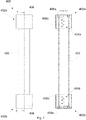
- FIG. 6 A further embodiment of the invention is shown in Fig. 6 , where the pressure relief conduit 326 is formed from a first tube 36 and a second tube 38 in fluid communication with each other.
- the first tube 36 comprises a first open end 36a and a second closed end 36b
- the second tube 38 comprises a first open end 38a and a second closed end 38b.
- the first and second tubes 36,38 are substantially J-shaped tubes, wherein a liquid trap is formed in each tube by the shaping of the tubes 36,38, the liquid traps located towards the first open ends 36a,38a of the respective tubes 36,38.
- the tubes 36,38 are arranged such that the first open end 36a of the first tube 36 is located at the first side 22a of the bulkhead 22, and the second open end 38a of the second tube 38 is located at the second side 22b of the bulkhead 22.
- a filter medium 40 comprising a mesh or sponge is provided in the first tube 36, and the second tube 38 extends through the body of the bulkhead 22, but it will be understood that any suitable arrangement of the components of the bulkhead assembly may be used.
- the first and second tubes 36,38 are positioned adjacent one another, and are communicatively coupled via an outlet channel 42 defined in the body of the tubes 36,38.
- the outlet channel 42 is located on the first and second tubes at a point between the first ends 36a,38a and second ends 36b,38b of the respective first and second tubes 36,38.
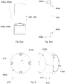
- FIG. 6 A further embodiment of a pressure relief conduit assembly 400 for use in a wind turbine blade is indicated in Figs. 6 and 7 .
- the pressure relief conduit assembly 400 comprises an open-ended tube 402.
- a plurality of ventilation holes are defined in the wall of the tube 402.
- a first set of ventilation holes 404a are defined near a first end 402a of the tube 402, with a second set of ventilation holes 404b defined near an opposed second end 402b of the tube 402.
- the tube 402 may be positioned to extend through a wind turbine blade bulkhead, or may be positioned to the side of a bulkhead having said first and second ends 402a,402b arranged on either side of the bulkhead, similar to the constructions shown in the previous embodiments.
- the tube 402 acts to equalise pressure across the bulkhead in the blade, providing a pressure release channel between either side of the bulkhead.
- the pressure relief conduit assembly 400 further comprises a pair of end caps 406,408, fitted to respective first and second ends 402a,402b of the tube 402.
- the end caps 406,408 comprise an end surface 406a,408a having respective collars 406b,408b depending therefrom.
- the caps 406,408 are arranged such that the end surfaces 406a,408a substantially close the respective open ends 402a,402b of the tube 402.
- the collars 406b,408b extend from the respective ends 402a,402b of the tube 402, to a location along the longitudinal length of the tube 402 beyond the location of the respective first and second sets of ventilation holes 404a,404b.
- the collars 406b,408b act as a cover or shield over the exposed ventilation holes 404a,404b defined in the external wall of the tube 402.
- the collars 406b,408b are spaced from the external surface of the tube 402, such that a gap is preserved between the collars 406b,408b and the openings of the ventilation holes 404a,404b. Accordingly, the arrangement of the collars 406b,408b and the ventilation holes 404a,404b in the tube wall acts to impede ingress of dirt and debris into the interior of the tube 402.
- the first and second caps 406,408 are substantially identical.
- the pressure relief conduit assembly 400 comprises a third cap design, indicated at 410.
- the second end cap 408 is replaced by a third end cap 410.
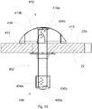
- the third cap 410 comprises an end section 410a arranged to substantially seal the second open end 402b of the tube 402, the third cap 410 further comprising a flared or umbrella-shaped collar 410b depending from said end section 410a.
- the flared collar 410b is arranged to extend along the length of the tube 402 from the second end 402b beyond the location of the second set of ventilation holes 404b.
- the third cap 410 further comprises at least one lug 412 to receive a bolt or other suitable securing device, the at least one lug 412 located at the free end of the flared collar 410b.
- the at least one lug 412 can be used to secure the third cap 410 to the surface 22a of a blade bulkhead 22, using a fastening device such as a bolt or screw (not shown). Additionally or alternatively, it will be understood that the third cap 410 may be arranged to secure the pressure relief conduit assembly to a surface of a blade wall.
- the at least one lug 412 is arranged to project from the free end of the flared collar 410b, such that when the third cap 410 is secured to the surface of the bulkhead as shown in Fig. 10 , a gap 414 is defined between the bulkhead surface 22a and the free end of the flared collar 410b.
- This embodiment allows for the pressure relief conduit assembly to be relatively easily secured to the general blade structure. While the third cap 410 shown in Figs. 9 and 10 comprises four separate lugs 412, it will be understood that any number of and arrangement of lugs may be used. Additionally or alternatively, the third cap 410 may be secured to a bulkhead or to a blade wall using an adhesive or other suitable securing method.
- end caps 406,408,410 may be fitted to the ends of the tube 402 using any suitable method, e.g. a press fitting or snap fitting arrangement, or the use of a suitable attachment device such as a bolt, screw, staple, etc. or an adhesive.
- a suitable attachment device such as a bolt, screw, staple, etc. or an adhesive.
- the tube and end caps shown have a substantially circular cross-sectional profile, it will be understood that the elements of the pressure relief conduit may have other cross-sectional shapes, e.g. square, rectangular, etc.
- Such a construction of a pressure relief conduit allows for relatively easy manufacture and assembly of the conduit for use in a wind turbine blade.
- the invention provides a pressure relief conduit for a wind turbine blade bulkhead assembly, having conduit openings at either side of the bulkhead, such that the pressure difference can be equalised across the bulkhead, preventing faults or cracks in the bulkhead assembly due to pressure differences.
- Liquid traps and/or filter media can be accommodated in the conduit to prevent the passage of liquids or other matter across the bulkhead.
Landscapes
- Engineering & Computer Science (AREA)
- Life Sciences & Earth Sciences (AREA)
- Sustainable Development (AREA)
- Sustainable Energy (AREA)
- Chemical & Material Sciences (AREA)
- Combustion & Propulsion (AREA)
- Mechanical Engineering (AREA)
- General Engineering & Computer Science (AREA)
- Wind Motors (AREA)
Claims (13)
- Pale d'éolienne comportant :une cloison étanche (22) mise en œuvre dans ladite pale d'éolienne (10) ; etau moins un conduit de décompression (226) ayant une première extrémité ouverte (226a) se trouvant au niveau d'un premier côté de ladite cloison et une deuxième extrémité ouverte (226b) se trouvant au niveau d'un deuxième côté de ladite cloison,dans laquelle ledit conduit de décompression (226) sert à égaliser la différence de pression entre ledit premier côté (22a) et ledit deuxième côté (22b) de ladite cloison,caractérisée en ce que ledit au moins un conduit de décompression (226) est agencé de manière adjacente par rapport à ladite cloison et mis en œuvre entre ladite cloison et le corps de pale ou la coque de pale extérieure de ladite pale d'éolienne.
- Pale d'éolienne selon la revendication 1, dans laquelle ladite cloison est assujettie au corps de pale par le biais d'une bride d'étanchéité mise en œuvre autour de la périphérie de ladite cloison, ladite bride d'étanchéité se trouvant entre ladite cloison et ledit corps de pale, dans laquelle ledit au moins un conduit de décompression s'étend au travers de ladite bride d'étanchéité, de manière adjacente par rapport à ladite cloison.
- Pale d'éolienne selon l'une quelconque des revendications précédentes, dans laquelle ledit au moins un conduit de décompression comporte au moins un piège à liquides.
- Pale d'éolienne selon l'une quelconque des revendications précédentes, dans laquelle ledit au moins un conduit de décompression est formé à partir d'un premier tube de libération de pression ayant une première extrémité ouverte et une deuxième extrémité fermée, et un deuxième tube de libération de pression ayant une première extrémité ouverte et une deuxième extrémité,
dans laquelle la première extrémité ouverte dudit conduit de décompression est formée par la première extrémité ouverte dudit premier tube de libération de pression,
dans laquelle la deuxième extrémité ouverte dudit conduit de décompression est formée par la première extrémité ouverte dudit deuxième tube de libération de pression, et
dans laquelle lesdits premier et deuxième tubes de décompression sont raccordés de manière communicative par le biais d'un canal de sortie s'étendant entre lesdits premier et deuxième tubes de décompression,
dans laquelle ledit canal de sortie est agencé sur ledit premier tube de décompression au niveau d'un point entre les première et deuxième extrémités dudit premier tube de décompression. - Pale d'éolienne selon l'une quelconque des revendications précédentes, dans laquelle la pale d'éolienne comporte un ensemble formant conduit de décompression, dans laquelle la pale comporte au moins un capuchon d'extrémité mis en œuvre au niveau de l'une desdites première ou deuxième extrémités ouvertes dudit au moins un conduit de décompression, ledit au moins un capuchon d'extrémité étant agencé pour sceller sensiblement ledit conduit au niveau de ladite première ou deuxième extrémité ouverte.
- Pale d'éolienne selon la revendication 5, dans laquelle au moins un trou de ventilation est défini dans une paroi dudit conduit de décompression, de préférence dans laquelle ledit au moins un trou de ventilation est mis en œuvre de manière adjacente par rapport audit au moins un capuchon d'extrémité.
- Pale d'éolienne selon la revendication 6, dans laquelle ledit au moins un capuchon comporte une pièce d'extrémité pour sceller sensiblement une extrémité ouverte dudit conduit, ledit au moins un capuchon d'extrémité comportant par ailleurs un collier dépendant de ladite pièce d'extrémité, ledit collier étant espacé de la paroi dudit conduit de décompression, et agissant pour protéger au moins une partie dudit au moins un trou de ventilation.
- Pale d'éolienne selon l'une quelconque des revendications 5 à 7, dans laquelle ledit au moins un capuchon d'extrémité est agencé pour être attaché à ladite cloison ou à une paroi interne de ladite pale d'éolienne.
- Pale d'éolienne selon l'une quelconque des revendications 5 à 8, dans laquelle un premier ensemble de trous de ventilation sont définis dans une paroi dudit conduit de décompression au niveau d'un emplacement adjacent par rapport à ladite première extrémité ouverte, et dans laquelle un deuxième ensemble de trous de ventilation sont définis dans une paroi dudit conduit de décompression au niveau d'un emplacement adjacent par rapport à ladite deuxième extrémité ouverte.
- Éolienne comportant au moins une pale d'éolienne selon l'une quelconque des revendications 1 à 9.
- Procédé de fabrication d'une pale d'éolienne selon l'une quelconque des revendications 1 à 9, le procédé comportant les étapes consistant à :mettre en œuvre une coque (34) de pale d'éolienne ;mettre en œuvre une cloison (22) se trouvant sur ou dans ladite pale d'éolienne (10) ; etmettre en œuvre au moins un conduit de décompression (226) ayant des ouvertures de conduit (226a, 226b) de chaque côté de ladite cloison, ledit conduit de décompression étant agencé pour égaliser la différence de pression en travers de ladite cloison, dans lequel ledit au moins un conduit de décompression (226) est agencé de manière adjacente par rapport à ladite cloison et mis en œuvre entre ladite cloison (22) et le corps de pale (34) ou la coque de pale extérieure de ladite éolienne.
- Procédé selon la revendication 11, dans lequel ladite étape consistant à mettre en œuvre au moins un conduit de décompression comporte l'étape consistant à mettre en œuvre un conduit qui se trouve de manière adjacente par rapport à ladite cloison, et l'étape consistant à s'étendre au travers d'un élément d'étanchéité ou d'une bride d'étanchéité qui est mis ou mise en œuvre autour de la périphérie de ladite cloison entre ladite cloison et ladite coque de pale d'éolienne.
- Procédé selon l'une quelconque des revendications 11 à 12, dans lequel le procédé comporte l'étape consistant à :
encastrer au moins une partie dudit conduit de décompression dans une paroi de ladite coque de pale d'éolienne, avant une étape consistant à installer ladite cloison dans ladite coque de pale d'éolienne.
Priority Applications (3)
| Application Number | Priority Date | Filing Date | Title |
|---|---|---|---|
| EP13792381.9A EP2920458B1 (fr) | 2012-11-19 | 2013-11-19 | Agencement de cloison pour une pale d'éolienne |
| EP20166815.9A EP3690233B1 (fr) | 2012-11-19 | 2013-11-19 | Agencement de cloison pour une pale d'éolienne |
| DK20166815.9T DK3690233T3 (da) | 2012-11-19 | 2013-11-19 | Skotarrangement til en vindmøllevinge |
Applications Claiming Priority (3)
| Application Number | Priority Date | Filing Date | Title |
|---|---|---|---|
| EP12193160 | 2012-11-19 | ||
| PCT/EP2013/074128 WO2014076288A1 (fr) | 2012-11-19 | 2013-11-19 | Agencement de cloison pour pale d'éolienne |
| EP13792381.9A EP2920458B1 (fr) | 2012-11-19 | 2013-11-19 | Agencement de cloison pour une pale d'éolienne |
Related Child Applications (1)
| Application Number | Title | Priority Date | Filing Date |
|---|---|---|---|
| EP20166815.9A Division EP3690233B1 (fr) | 2012-11-19 | 2013-11-19 | Agencement de cloison pour une pale d'éolienne |
Publications (2)
| Publication Number | Publication Date |
|---|---|
| EP2920458A1 EP2920458A1 (fr) | 2015-09-23 |
| EP2920458B1 true EP2920458B1 (fr) | 2020-04-01 |
Family
ID=47278132
Family Applications (2)
| Application Number | Title | Priority Date | Filing Date |
|---|---|---|---|
| EP20166815.9A Active EP3690233B1 (fr) | 2012-11-19 | 2013-11-19 | Agencement de cloison pour une pale d'éolienne |
| EP13792381.9A Active EP2920458B1 (fr) | 2012-11-19 | 2013-11-19 | Agencement de cloison pour une pale d'éolienne |
Family Applications Before (1)
| Application Number | Title | Priority Date | Filing Date |
|---|---|---|---|
| EP20166815.9A Active EP3690233B1 (fr) | 2012-11-19 | 2013-11-19 | Agencement de cloison pour une pale d'éolienne |
Country Status (5)
| Country | Link |
|---|---|
| US (2) | US10100806B2 (fr) |
| EP (2) | EP3690233B1 (fr) |
| CN (1) | CN105026751B (fr) |
| DK (2) | DK3690233T3 (fr) |
| WO (1) | WO2014076288A1 (fr) |
Cited By (1)
| Publication number | Priority date | Publication date | Assignee | Title |
|---|---|---|---|---|
| WO2025067618A1 (fr) * | 2023-09-28 | 2025-04-03 | Vestas Wind Systems A/S | Collecteur de déblais de forage |
Families Citing this family (6)
| Publication number | Priority date | Publication date | Assignee | Title |
|---|---|---|---|---|
| CN108626076A (zh) * | 2017-03-21 | 2018-10-09 | 中材科技风电叶片股份有限公司 | 叶根挡板与叶根的连接结构 |
| CN107559156A (zh) * | 2017-10-26 | 2018-01-09 | 中材科技风电叶片股份有限公司 | 叶根挡板以及风电叶片 |
| EP3870841B1 (fr) | 2018-10-22 | 2024-04-10 | TPI Composites, Inc. | Installation d'âme d'éolienne sans portique avec chauffage |
| MA56023A (fr) * | 2019-06-03 | 2022-04-06 | Lm Wind Power As | Cloison pour pale d'éolienne et procédé d'installation d'une cloison dans une pale d'éolienne |
| CN112659581A (zh) * | 2021-01-15 | 2021-04-16 | 洛阳双瑞风电叶片有限公司 | 一种预埋叶片用固定组件及预埋叶片的制作方法 |
| CN112943527B (zh) * | 2021-04-09 | 2023-01-10 | 吉林重通成飞新材料股份公司 | 一种风电叶片柔性叶根挡板结构 |
Family Cites Families (8)
| Publication number | Priority date | Publication date | Assignee | Title |
|---|---|---|---|---|
| GB9102665D0 (en) * | 1991-02-07 | 1991-03-27 | Lawson Tancred Sir H | The manufacture of turbine blades for wind turbines |
| JP4730792B2 (ja) * | 2004-11-10 | 2011-07-20 | ヴェスタス ウィンド システムズ エー/エス | 風力タービンの塔の部分、開口部のカバー装置、及び、風力タービンの塔の部分の製造方法及びその使用 |
| DE102006055091A1 (de) * | 2006-11-21 | 2008-05-29 | Repower Systems Ag | Schott einer Windenergieanlage |
| US8123488B2 (en) * | 2007-09-17 | 2012-02-28 | General Electric Company | System and method for joining turbine blades |
| WO2011144971A1 (fr) * | 2010-05-20 | 2011-11-24 | Tecsis Tecnologia E Sistemas Avançados Ltda | Cloison pour une base de pale d'aérogénérateur |
| DE102010042530B4 (de) * | 2010-10-15 | 2015-04-30 | Senvion Se | Schott einer Windenergieanlage |
| DK2497941T3 (da) | 2011-03-08 | 2019-10-21 | Lm Wp Patent Holding As | Vindmøllevinge omfattende et rodendeskot |
| US20120141287A1 (en) * | 2011-08-29 | 2012-06-07 | General Electric Company | Wind turbine rotor blade joint |
-
2013
- 2013-11-19 DK DK20166815.9T patent/DK3690233T3/da active
- 2013-11-19 DK DK13792381.9T patent/DK2920458T3/da active
- 2013-11-19 WO PCT/EP2013/074128 patent/WO2014076288A1/fr not_active Ceased
- 2013-11-19 EP EP20166815.9A patent/EP3690233B1/fr active Active
- 2013-11-19 US US14/442,018 patent/US10100806B2/en active Active
- 2013-11-19 EP EP13792381.9A patent/EP2920458B1/fr active Active
- 2013-11-19 CN CN201380070886.0A patent/CN105026751B/zh active Active
-
2018
- 2018-09-11 US US16/127,632 patent/US10781790B2/en active Active
Non-Patent Citations (1)
| Title |
|---|
| None * |
Cited By (1)
| Publication number | Priority date | Publication date | Assignee | Title |
|---|---|---|---|---|
| WO2025067618A1 (fr) * | 2023-09-28 | 2025-04-03 | Vestas Wind Systems A/S | Collecteur de déblais de forage |
Also Published As
| Publication number | Publication date |
|---|---|
| EP3690233B1 (fr) | 2022-05-11 |
| EP3690233A1 (fr) | 2020-08-05 |
| US20150267680A1 (en) | 2015-09-24 |
| DK2920458T3 (da) | 2020-07-13 |
| WO2014076288A1 (fr) | 2014-05-22 |
| US20190017493A1 (en) | 2019-01-17 |
| US10100806B2 (en) | 2018-10-16 |
| CN105026751B (zh) | 2019-04-16 |
| EP2920458A1 (fr) | 2015-09-23 |
| CN105026751A (zh) | 2015-11-04 |
| US10781790B2 (en) | 2020-09-22 |
| DK3690233T3 (da) | 2022-08-15 |
Similar Documents
| Publication | Publication Date | Title |
|---|---|---|
| US10781790B2 (en) | Bulkhead arrangement for a wind turbine blade | |
| EP2235364B1 (fr) | Rebord flexible de bouclier de pied de pale d'éolienne | |
| CN110352299B (zh) | 具有液体保留特性的机舱 | |
| EP3169895B2 (fr) | Coque d'extension pour pale d'éolienne | |
| EP2908002B1 (fr) | Ensemble de cloison pour pale de turbine éolienne | |
| CN109891089B (zh) | 包括隔板的风力涡轮机叶片 | |
| EP3568593B1 (fr) | Trappes de nacelle et plateforme d'hélitreuillage | |
| EP3673170B1 (fr) | Dispositif de levage et procédé d'installation d'un module de cloison dans une pale de turbine éolienne | |
| BR112017003196B1 (pt) | Componente de turbina eólica reforçado | |
| CN211343209U (zh) | 轮毂 | |
| EP3568588B1 (fr) | Spinner pour moyeu d'éolienne | |
| KR20160148588A (ko) | 풍력 발전소용 에어 덕트, 풍력 발전소, 에어 덕트의 제조방법 및 에어 덕트로 풍력 발전소를 개조하는 방법 | |
| EP4660447A1 (fr) | Procédés et ensembles pour installer des douilles dans la racine d'une pale d'éolienne | |
| CN111075640B (zh) | 轮毂 |
Legal Events
| Date | Code | Title | Description |
|---|---|---|---|
| PUAI | Public reference made under article 153(3) epc to a published international application that has entered the european phase |
Free format text: ORIGINAL CODE: 0009012 |
|
| 17P | Request for examination filed |
Effective date: 20150619 |
|
| AK | Designated contracting states |
Kind code of ref document: A1 Designated state(s): AL AT BE BG CH CY CZ DE DK EE ES FI FR GB GR HR HU IE IS IT LI LT LU LV MC MK MT NL NO PL PT RO RS SE SI SK SM TR |
|
| AX | Request for extension of the european patent |
Extension state: BA ME |
|
| DAX | Request for extension of the european patent (deleted) | ||
| STAA | Information on the status of an ep patent application or granted ep patent |
Free format text: STATUS: EXAMINATION IS IN PROGRESS |
|
| 17Q | First examination report despatched |
Effective date: 20180411 |
|
| GRAP | Despatch of communication of intention to grant a patent |
Free format text: ORIGINAL CODE: EPIDOSNIGR1 |
|
| STAA | Information on the status of an ep patent application or granted ep patent |
Free format text: STATUS: GRANT OF PATENT IS INTENDED |
|
| INTG | Intention to grant announced |
Effective date: 20191017 |
|
| GRAS | Grant fee paid |
Free format text: ORIGINAL CODE: EPIDOSNIGR3 |
|
| GRAA | (expected) grant |
Free format text: ORIGINAL CODE: 0009210 |
|
| STAA | Information on the status of an ep patent application or granted ep patent |
Free format text: STATUS: THE PATENT HAS BEEN GRANTED |
|
| AK | Designated contracting states |
Kind code of ref document: B1 Designated state(s): AL AT BE BG CH CY CZ DE DK EE ES FI FR GB GR HR HU IE IS IT LI LT LU LV MC MK MT NL NO PL PT RO RS SE SI SK SM TR |
|
| REG | Reference to a national code |
Ref country code: GB Ref legal event code: FG4D |
|
| REG | Reference to a national code |
Ref country code: CH Ref legal event code: EP Ref country code: AT Ref legal event code: REF Ref document number: 1251660 Country of ref document: AT Kind code of ref document: T Effective date: 20200415 |
|
| REG | Reference to a national code |
Ref country code: DE Ref legal event code: R096 Ref document number: 602013067489 Country of ref document: DE |
|
| REG | Reference to a national code |
Ref country code: IE Ref legal event code: FG4D |
|
| REG | Reference to a national code |
Ref country code: NL Ref legal event code: FP |
|
| REG | Reference to a national code |
Ref country code: DK Ref legal event code: T3 Effective date: 20200707 |
|
| PG25 | Lapsed in a contracting state [announced via postgrant information from national office to epo] |
Ref country code: BG Free format text: LAPSE BECAUSE OF FAILURE TO SUBMIT A TRANSLATION OF THE DESCRIPTION OR TO PAY THE FEE WITHIN THE PRESCRIBED TIME-LIMIT Effective date: 20200701 |
|
| REG | Reference to a national code |
Ref country code: LT Ref legal event code: MG4D |
|
| PG25 | Lapsed in a contracting state [announced via postgrant information from national office to epo] |
Ref country code: SE Free format text: LAPSE BECAUSE OF FAILURE TO SUBMIT A TRANSLATION OF THE DESCRIPTION OR TO PAY THE FEE WITHIN THE PRESCRIBED TIME-LIMIT Effective date: 20200401 Ref country code: LT Free format text: LAPSE BECAUSE OF FAILURE TO SUBMIT A TRANSLATION OF THE DESCRIPTION OR TO PAY THE FEE WITHIN THE PRESCRIBED TIME-LIMIT Effective date: 20200401 Ref country code: PT Free format text: LAPSE BECAUSE OF FAILURE TO SUBMIT A TRANSLATION OF THE DESCRIPTION OR TO PAY THE FEE WITHIN THE PRESCRIBED TIME-LIMIT Effective date: 20200817 Ref country code: IS Free format text: LAPSE BECAUSE OF FAILURE TO SUBMIT A TRANSLATION OF THE DESCRIPTION OR TO PAY THE FEE WITHIN THE PRESCRIBED TIME-LIMIT Effective date: 20200801 Ref country code: CZ Free format text: LAPSE BECAUSE OF FAILURE TO SUBMIT A TRANSLATION OF THE DESCRIPTION OR TO PAY THE FEE WITHIN THE PRESCRIBED TIME-LIMIT Effective date: 20200401 Ref country code: FI Free format text: LAPSE BECAUSE OF FAILURE TO SUBMIT A TRANSLATION OF THE DESCRIPTION OR TO PAY THE FEE WITHIN THE PRESCRIBED TIME-LIMIT Effective date: 20200401 Ref country code: NO Free format text: LAPSE BECAUSE OF FAILURE TO SUBMIT A TRANSLATION OF THE DESCRIPTION OR TO PAY THE FEE WITHIN THE PRESCRIBED TIME-LIMIT Effective date: 20200701 Ref country code: GR Free format text: LAPSE BECAUSE OF FAILURE TO SUBMIT A TRANSLATION OF THE DESCRIPTION OR TO PAY THE FEE WITHIN THE PRESCRIBED TIME-LIMIT Effective date: 20200702 |
|
| REG | Reference to a national code |
Ref country code: AT Ref legal event code: MK05 Ref document number: 1251660 Country of ref document: AT Kind code of ref document: T Effective date: 20200401 |
|
| PG25 | Lapsed in a contracting state [announced via postgrant information from national office to epo] |
Ref country code: LV Free format text: LAPSE BECAUSE OF FAILURE TO SUBMIT A TRANSLATION OF THE DESCRIPTION OR TO PAY THE FEE WITHIN THE PRESCRIBED TIME-LIMIT Effective date: 20200401 Ref country code: RS Free format text: LAPSE BECAUSE OF FAILURE TO SUBMIT A TRANSLATION OF THE DESCRIPTION OR TO PAY THE FEE WITHIN THE PRESCRIBED TIME-LIMIT Effective date: 20200401 Ref country code: HR Free format text: LAPSE BECAUSE OF FAILURE TO SUBMIT A TRANSLATION OF THE DESCRIPTION OR TO PAY THE FEE WITHIN THE PRESCRIBED TIME-LIMIT Effective date: 20200401 |
|
| PG25 | Lapsed in a contracting state [announced via postgrant information from national office to epo] |
Ref country code: AL Free format text: LAPSE BECAUSE OF FAILURE TO SUBMIT A TRANSLATION OF THE DESCRIPTION OR TO PAY THE FEE WITHIN THE PRESCRIBED TIME-LIMIT Effective date: 20200401 |
|
| REG | Reference to a national code |
Ref country code: DE Ref legal event code: R097 Ref document number: 602013067489 Country of ref document: DE |
|
| PG25 | Lapsed in a contracting state [announced via postgrant information from national office to epo] |
Ref country code: RO Free format text: LAPSE BECAUSE OF FAILURE TO SUBMIT A TRANSLATION OF THE DESCRIPTION OR TO PAY THE FEE WITHIN THE PRESCRIBED TIME-LIMIT Effective date: 20200401 Ref country code: IT Free format text: LAPSE BECAUSE OF FAILURE TO SUBMIT A TRANSLATION OF THE DESCRIPTION OR TO PAY THE FEE WITHIN THE PRESCRIBED TIME-LIMIT Effective date: 20200401 Ref country code: EE Free format text: LAPSE BECAUSE OF FAILURE TO SUBMIT A TRANSLATION OF THE DESCRIPTION OR TO PAY THE FEE WITHIN THE PRESCRIBED TIME-LIMIT Effective date: 20200401 Ref country code: SM Free format text: LAPSE BECAUSE OF FAILURE TO SUBMIT A TRANSLATION OF THE DESCRIPTION OR TO PAY THE FEE WITHIN THE PRESCRIBED TIME-LIMIT Effective date: 20200401 Ref country code: AT Free format text: LAPSE BECAUSE OF FAILURE TO SUBMIT A TRANSLATION OF THE DESCRIPTION OR TO PAY THE FEE WITHIN THE PRESCRIBED TIME-LIMIT Effective date: 20200401 Ref country code: ES Free format text: LAPSE BECAUSE OF FAILURE TO SUBMIT A TRANSLATION OF THE DESCRIPTION OR TO PAY THE FEE WITHIN THE PRESCRIBED TIME-LIMIT Effective date: 20200401 |
|
| PLBE | No opposition filed within time limit |
Free format text: ORIGINAL CODE: 0009261 |
|
| STAA | Information on the status of an ep patent application or granted ep patent |
Free format text: STATUS: NO OPPOSITION FILED WITHIN TIME LIMIT |
|
| PG25 | Lapsed in a contracting state [announced via postgrant information from national office to epo] |
Ref country code: SK Free format text: LAPSE BECAUSE OF FAILURE TO SUBMIT A TRANSLATION OF THE DESCRIPTION OR TO PAY THE FEE WITHIN THE PRESCRIBED TIME-LIMIT Effective date: 20200401 Ref country code: PL Free format text: LAPSE BECAUSE OF FAILURE TO SUBMIT A TRANSLATION OF THE DESCRIPTION OR TO PAY THE FEE WITHIN THE PRESCRIBED TIME-LIMIT Effective date: 20200401 |
|
| 26N | No opposition filed |
Effective date: 20210112 |
|
| PG25 | Lapsed in a contracting state [announced via postgrant information from national office to epo] |
Ref country code: SI Free format text: LAPSE BECAUSE OF FAILURE TO SUBMIT A TRANSLATION OF THE DESCRIPTION OR TO PAY THE FEE WITHIN THE PRESCRIBED TIME-LIMIT Effective date: 20200401 |
|
| PG25 | Lapsed in a contracting state [announced via postgrant information from national office to epo] |
Ref country code: MC Free format text: LAPSE BECAUSE OF FAILURE TO SUBMIT A TRANSLATION OF THE DESCRIPTION OR TO PAY THE FEE WITHIN THE PRESCRIBED TIME-LIMIT Effective date: 20200401 |
|
| REG | Reference to a national code |
Ref country code: CH Ref legal event code: PL |
|
| PG25 | Lapsed in a contracting state [announced via postgrant information from national office to epo] |
Ref country code: LU Free format text: LAPSE BECAUSE OF NON-PAYMENT OF DUE FEES Effective date: 20201119 |
|
| REG | Reference to a national code |
Ref country code: BE Ref legal event code: MM Effective date: 20201130 |
|
| PG25 | Lapsed in a contracting state [announced via postgrant information from national office to epo] |
Ref country code: CH Free format text: LAPSE BECAUSE OF NON-PAYMENT OF DUE FEES Effective date: 20201130 Ref country code: LI Free format text: LAPSE BECAUSE OF NON-PAYMENT OF DUE FEES Effective date: 20201130 |
|
| PG25 | Lapsed in a contracting state [announced via postgrant information from national office to epo] |
Ref country code: IE Free format text: LAPSE BECAUSE OF NON-PAYMENT OF DUE FEES Effective date: 20201119 |
|
| PG25 | Lapsed in a contracting state [announced via postgrant information from national office to epo] |
Ref country code: TR Free format text: LAPSE BECAUSE OF FAILURE TO SUBMIT A TRANSLATION OF THE DESCRIPTION OR TO PAY THE FEE WITHIN THE PRESCRIBED TIME-LIMIT Effective date: 20200401 Ref country code: MT Free format text: LAPSE BECAUSE OF FAILURE TO SUBMIT A TRANSLATION OF THE DESCRIPTION OR TO PAY THE FEE WITHIN THE PRESCRIBED TIME-LIMIT Effective date: 20200401 Ref country code: CY Free format text: LAPSE BECAUSE OF FAILURE TO SUBMIT A TRANSLATION OF THE DESCRIPTION OR TO PAY THE FEE WITHIN THE PRESCRIBED TIME-LIMIT Effective date: 20200401 |
|
| PG25 | Lapsed in a contracting state [announced via postgrant information from national office to epo] |
Ref country code: MK Free format text: LAPSE BECAUSE OF FAILURE TO SUBMIT A TRANSLATION OF THE DESCRIPTION OR TO PAY THE FEE WITHIN THE PRESCRIBED TIME-LIMIT Effective date: 20200401 |
|
| PG25 | Lapsed in a contracting state [announced via postgrant information from national office to epo] |
Ref country code: BE Free format text: LAPSE BECAUSE OF NON-PAYMENT OF DUE FEES Effective date: 20201130 |
|
| P01 | Opt-out of the competence of the unified patent court (upc) registered |
Effective date: 20230522 |
|
| PGFP | Annual fee paid to national office [announced via postgrant information from national office to epo] |
Ref country code: NL Payment date: 20251022 Year of fee payment: 13 |
|
| PGFP | Annual fee paid to national office [announced via postgrant information from national office to epo] |
Ref country code: DE Payment date: 20251022 Year of fee payment: 13 |
|
| PGFP | Annual fee paid to national office [announced via postgrant information from national office to epo] |
Ref country code: GB Payment date: 20251022 Year of fee payment: 13 |
|
| PGFP | Annual fee paid to national office [announced via postgrant information from national office to epo] |
Ref country code: DK Payment date: 20251022 Year of fee payment: 13 |
|
| PGFP | Annual fee paid to national office [announced via postgrant information from national office to epo] |
Ref country code: FR Payment date: 20251022 Year of fee payment: 13 |