EP2920467B1 - Stators métalliques - Google Patents
Stators métalliques Download PDFInfo
- Publication number
- EP2920467B1 EP2920467B1 EP13792223.3A EP13792223A EP2920467B1 EP 2920467 B1 EP2920467 B1 EP 2920467B1 EP 13792223 A EP13792223 A EP 13792223A EP 2920467 B1 EP2920467 B1 EP 2920467B1
- Authority
- EP
- European Patent Office
- Prior art keywords
- disks
- rigid
- disk stack
- stator
- rings
- Prior art date
- Legal status (The legal status is an assumption and is not a legal conclusion. Google has not performed a legal analysis and makes no representation as to the accuracy of the status listed.)
- Active
Links
Images



Classifications
-
- F—MECHANICAL ENGINEERING; LIGHTING; HEATING; WEAPONS; BLASTING
- F04—POSITIVE - DISPLACEMENT MACHINES FOR LIQUIDS; PUMPS FOR LIQUIDS OR ELASTIC FLUIDS
- F04C—ROTARY-PISTON, OR OSCILLATING-PISTON, POSITIVE-DISPLACEMENT MACHINES FOR LIQUIDS; ROTARY-PISTON, OR OSCILLATING-PISTON, POSITIVE-DISPLACEMENT PUMPS
- F04C2/00—Rotary-piston machines or pumps
- F04C2/08—Rotary-piston machines or pumps of intermeshing-engagement type, i.e. with engagement of co-operating members similar to that of toothed gearing
- F04C2/10—Rotary-piston machines or pumps of intermeshing-engagement type, i.e. with engagement of co-operating members similar to that of toothed gearing of internal-axis type with the outer member having more teeth or tooth-equivalents, e.g. rollers, than the inner member
- F04C2/107—Rotary-piston machines or pumps of intermeshing-engagement type, i.e. with engagement of co-operating members similar to that of toothed gearing of internal-axis type with the outer member having more teeth or tooth-equivalents, e.g. rollers, than the inner member with helical teeth
- F04C2/1071—Rotary-piston machines or pumps of intermeshing-engagement type, i.e. with engagement of co-operating members similar to that of toothed gearing of internal-axis type with the outer member having more teeth or tooth-equivalents, e.g. rollers, than the inner member with helical teeth the inner and outer member having a different number of threads and one of the two being made of elastic materials, e.g. Moineau type
- F04C2/1073—Rotary-piston machines or pumps of intermeshing-engagement type, i.e. with engagement of co-operating members similar to that of toothed gearing of internal-axis type with the outer member having more teeth or tooth-equivalents, e.g. rollers, than the inner member with helical teeth the inner and outer member having a different number of threads and one of the two being made of elastic materials, e.g. Moineau type where one member is stationary while the other member rotates and orbits
- F04C2/1075—Construction of the stationary member
-
- F—MECHANICAL ENGINEERING; LIGHTING; HEATING; WEAPONS; BLASTING
- F04—POSITIVE - DISPLACEMENT MACHINES FOR LIQUIDS; PUMPS FOR LIQUIDS OR ELASTIC FLUIDS
- F04C—ROTARY-PISTON, OR OSCILLATING-PISTON, POSITIVE-DISPLACEMENT MACHINES FOR LIQUIDS; ROTARY-PISTON, OR OSCILLATING-PISTON, POSITIVE-DISPLACEMENT PUMPS
- F04C2230/00—Manufacture
- F04C2230/20—Manufacture essentially without removing material
- F04C2230/22—Manufacture essentially without removing material by sintering
-
- F—MECHANICAL ENGINEERING; LIGHTING; HEATING; WEAPONS; BLASTING
- F04—POSITIVE - DISPLACEMENT MACHINES FOR LIQUIDS; PUMPS FOR LIQUIDS OR ELASTIC FLUIDS
- F04C—ROTARY-PISTON, OR OSCILLATING-PISTON, POSITIVE-DISPLACEMENT MACHINES FOR LIQUIDS; ROTARY-PISTON, OR OSCILLATING-PISTON, POSITIVE-DISPLACEMENT PUMPS
- F04C2230/00—Manufacture
- F04C2230/20—Manufacture essentially without removing material
- F04C2230/23—Manufacture essentially without removing material by permanently joining parts together
-
- Y—GENERAL TAGGING OF NEW TECHNOLOGICAL DEVELOPMENTS; GENERAL TAGGING OF CROSS-SECTIONAL TECHNOLOGIES SPANNING OVER SEVERAL SECTIONS OF THE IPC; TECHNICAL SUBJECTS COVERED BY FORMER USPC CROSS-REFERENCE ART COLLECTIONS [XRACs] AND DIGESTS
- Y10—TECHNICAL SUBJECTS COVERED BY FORMER USPC
- Y10T—TECHNICAL SUBJECTS COVERED BY FORMER US CLASSIFICATION
- Y10T29/00—Metal working
- Y10T29/49—Method of mechanical manufacture
- Y10T29/49229—Prime mover or fluid pump making
- Y10T29/49236—Fluid pump or compressor making
- Y10T29/49242—Screw or gear type, e.g., Moineau type
Definitions
- This invention relates generally to gear pumps, and more particularly, to internally rigid laminated stators for helical gear pumps and motors.
- Today's downhole drilling motors usually are of the convoluted helical gear expansible chamber construction because of their high power performance and relatively thin profile and because the drilling fluid is pumped through the motor to operate the motor and is used to wash the chips away from the drilling area. These motors are capable of providing direct drive for the drill bit and can be used in directional drilling or deep drilling.
- the working portion of the motor comprises an outer housing having an internal multi-lobed stator mounted therein and a multi-lobed rotor disposed within the stator.
- the rotor has one less lobe than the stator to facilitate pumping rotation.
- the rotor and stator both have helical lobes and their lobes engage to form sealing surfaces which are acted on by the drilling fluid to drive the rotor within the stator.
- the rotor is turned by an external power source to facilitate pumping of the fluid.
- a downhole drilling motor uses pumped fluid to rotate the rotor while the helical gear pump turns the rotor to pump fluid.
- one or the other of the rotor/stator shape is made of an elastomeric material to maintain a seal there between, as well as to allow the complex shape to be manufactured.
- an elastomer may still be used in pumps or motors having this type of stator at the interface between the rotor and stator to coat the stator and avoid metal-to-metal contact between the rotor and stator
- the function of the elastomer in a rigid stator is primarily to provide a resilient seal between the rotor/stator, and to help compensate for machining variations and tolerances.
- a low modulus elastomer sleeve is not required to maintain the "geometry" of the stator lobes under conditions of high unit loading, which is a job ill suited to a low modulus material. Therefore, it is this well known that a rigid helical stator with a thin uniform elastomeric sealing member on its lobed surfaces is superior in performance to typical elastomeric stators 15 of relatively thick and varying cross-sections.
- stator that is extremely rigid and which forms the internal helical lobes that form the rotor cavity that is inexpensive to produce and is durable and reliable in operation as will be discussed in greater detail below.
- stator assemblies including a stack of disk-shaped stator elements are disclosed in US 2010/0284843 A1 , US 3 975 121 A and GB 1 238 237 A .
- a stator for a helical gear device includes a plurality of rigid disks, a bonding member fixedly attached to the rigid disks to bond the rigid disks together as a disk stack, and a plurality of rigid support rings fixedly attached to the disk stack.
- the bonded rigid disks define a helically convoluted elongated chamber, with each of the rigid disks having an interior surface with radially extending lobes defining a central aperture.
- the rigid disks are concentrically aligned face-to-face in a stacked helical relationship with one another with each disk rotated with respect to an adjacent one of the rigid disks progressively along a length of the disk stack in one direction of rotation to define a helically convoluted elongated chamber.
- the plurality of rigid support rings includes a first ring and a second ring fitted concentrically at opposite ends of the disk stack against the respective end rigid disks of the disk stack.
- the rings are sized with an inside diameter substantially equal to the major diameter of the central aperture defined by the radially extending lobes of the rigid disks and support a rotor nutatively disposed in the helically convoluted elongated chamber by contact with the rotor.
- the support rings are preferably annular.
- a method of making a stator for a helical gear device includes the steps of: a) stacking a plurality of rigid disks in aligned face-to-face stacked relationship with one another with each disk rotated with respect to the next adjacent disks progressively along the length of the aligned disks in one direction of rotation to define a helically convoluted elongated chamber, each of said disks defining in cross-section an opening defining radially extending lobes corresponding to the size and shape of a rotor; b) fixing the rigid disks together to make a bonded disk stack; c) coupling a first rigid support ring concentrically to a rigid disk at a first end of the disk stack; and d) coupling a second rigid support ring concentrically to a rigid disk at a second end of the disk stack opposite the first end, the first and second rings being sized with an inside diameter substantially equal to the major diameter of the central aperture defined by the radi
- Examples of the present invention include a stator for a helical gear device that is formed from multiple rigid disks and support rings bonded to the disks.
- the disks are similar and preferably, but not necessarily, identical disks. Each disk forms part of a profile consisting of radially equally spaced or opened lobes which interact with the convex portions of rotor lobes.
- the disks are arranged into a desired helical configuration and bonded to one another to form a disk stack defining a helically convoluted elongated chamber therein.
- the support rings include a first support ring and a second support ring fixed concentrically at opposite ends of the disk stack against respective end disks of the disk stack.
- the rings are sized with an inside diameter substantially equal to the major diameter of the central aperture defined by the radially extending lobes of the rigid disks.
- a rotor rotates and nutates inside the helically convoluted elongated chamber of the stator, it is supported at both ends of the disk stack by the support rings touching the tips of the rotor lobes.
- the disk stack may be placed into a tube and bonded to the tube to provide further structural support to the disks. While not being limited to a particular theory, an internal coating may be applied to the interior surface of the bonded disks.
- the current invention includes a manufacturing process for making an internally rigid stator for pump and motor applications utilizing support rings on opposite sides of a lobed internal helical profile which preferably contains one more lobe than the rotor.
- This profile is made from a laminated stack of thin disks bonded to one another to form the desired stator profile.
- the disks which make up the inner rigid profile may be manufactured in a variety of ways, with preferred methods including machining via laser, water jet, electrical discharge machining (EDM), milling etc. or a stamping/ punching process. They may also be made to shape originally by casting, powder metallurgy or any similar process.
- the driving force behind the method of disk manufacture is the disk material and the cost of manufacture for that material.
- stamping is cost effective for most disks made of metals but unfeasible for disks made of ceramics.
- the thickness of the disks determines the size of the step between the disk edges as they are aligned into the desired helical formation; the thicker the disk the larger the step.
- the various components may be constructed of any material suitable for contact with the human body, the preferred materials of the disks and support rings are metal, for example, steel.
- the disks may be assembled into a helix by stacking the disks about a mandrel or jig that interacts with lobed features of the disks.
- the disks may be made in such a way that openings following the helix of the stator for passage of controls, sensors, fluid etc. are created down the length of the stator.
- the disks are then bonded to one another to form the disk stack.
- Support rings having an inner diameter matching the maximum inner diameter of the lobed disks are bonded to the end disks of the disk stack.
- the disk stack and bonded support rings may then be inserted into the stator tube, where it is then bonded or mechanically fixed to the tube housing.
- the stator may or may not have an inner lining which is generally composed of an elastomer, plastic, ceramic or metal.
- Fig. 1 depicts an exemplary embodiment of a stator 10 partially cut away showing an cylindrical outer housing or tube 12, a disk stack 14 of a plurality of like-shaped lobed disks 16, and annular support rings 18.
- the disks 16 in the disk stack 14 share a common centerline with each disk rotated slightly from the disks on either side to form a helical winding inside the housing 12.
- the disks 16 may be placed into a helical configuration of the disk stack 14 by stacking the disks onto an alignment assembly via means for stacking, including an alignment mandrel/core with a profile that catches lobes 20 of the disks with its profile cut in a helical pattern in the alignment core, as readily understood by a skilled artisan ( Fig. 3 ).
- the disks may also be aligned with an alignment assembly including a jig which interacts with disk features other than the inner profile or through features built into the disks (e.g., apertures through the disk lobes) that rotate each disk slightly relative to neighboring disks.
- an alignment assembly including a jig which interacts with disk features other than the inner profile or through features built into the disks (e.g., apertures through the disk lobes) that rotate each disk slightly relative to neighboring disks.
- the disk stack 14 is then bonded together by means for fixing the rigid disks together including a bonding member provided by, for example, welding, fusing, soldering, brazing, sintering, diffusion bonding, mechanical fastening, or via an adhesive bond.
- the tube 12, which preferably is made of metal, may be straightened, chamfered, machined, cleaned and heated as required and understood by a skilled artisan.
- the tube 12 is another bonding member that may then be slid over the tube 12 and bonded to the tube by means for bonding (e.g ., welding, fusing, soldering, brazing, sintering, diffusion bonding, mechanical fastening, adhesive) as another means for fixing the rigid disk together.
- the alignment assembly may then be removed from the disk stack 14. It should be noted that depending on the disk stack alignment methodology, it may be required or preferred to insert the stack 14 into the outer housing 12 without the alignment tooling entering the outer housing as well.
- Support rings 18 are fitted concentrically to and fixedly attached to opposite ends of the disk stack 14 preferably by mechanically or chemically bonding the support rings 18 to the disk 16 located at each end of the disk stack as a means for coupling the rings to the disk stack.
- the support rings 18 lie at the ends of the disk stack that define the helically convoluted elongated chamber profiled at the inside of the stator 10.
- the support rings 18 are preferably annular and sized so that the inside diameter is the same as the major ( e.g ., maximum) diameter of the profile formed in the lobed disks 16.
- the support rings 18 have an inside diameter substantially equal to the major diameter of the interior surface of the lobed disks so that the interior surface of the support ring and of the end disk meet at the major diameter of the lobed disk. This means that as a rotor 24 rotates and nutates inside the helically convoluted elongated chamber of the stator 10, it is supported at both ends of the disk stack 14 by the support rings 18 touching the tips of the rotor lobes 26. This means that the full force of the rotor's inertia from the eccentric path that it describes is not borne by the disks 16 alone, thus increasing their life.
- the support rings may also be slid into the tube 12 and bonded to the tube by means for bonding (e.g ., welding, fusing, soldering, brazing, sintering, diffusion bonding, mechanical fastening, adhesive) to become a monolithic structure.
- bonding e.g ., welding, fusing, soldering, brazing, sintering, diffusion bonding, mechanical fastening, adhesive
- the lobed disks 16 are stacked with a small angular difference between each disk and the disks to either side of it, which can be seen in encircled section 28 of Fig. 1 .
- This small angular difference between successive disks 16, as shown by the enlarged view in Fig. 2 may produce a surface that is shaped like a saw tooth from the perspective of the rotor 24. This means that as the fluid passes through the motor, bypassed fluid that leaks through the gap between the rotor 24 and stator 10 must cross many small tight spots, with larger gaps in between.
- each disk 16 includes a convoluted cavity 22 with the exemplary disk having a number of equally spaced symmetrical lobes 20 radially extending toward the centerline.
- the disks Preferably all of the disks have substantially identical construction and dimension.
- the width W of each disk ( Fig. 4 ) while most preferably the same thickness of, for example, about 0.0625 inches, may vary between about 0.005 inches thick to several inches thick within the scope of the invention.
- the support rings 18 preferably have a width greater than the width W of each disk to bear the force of the rotor's inertia and lessen any excessive force previously borne by the disks 16 at the ends of the disk stack.
- Fig. 5 depicts an exemplary alignment assembly 30 that may be used to stack the disks 16 into the proper alignment, and allows the bonded disk stack 14 and the support rings 18 to be inserted into the outer housing tube 12.
- the alignment assembly 30 includes an alignment plate 32 coupled to a spacer bushing 34 that insure the disk stack 14 is in the right position relative to the outer housing tube. For example, when the tube 12 is placed against the alignment plate 32, the spacer bushing 34 spatially offsets the disk stack 14 within the tube generally by the length of the spacer bushing.
- the alignment assembly 30 also includes an alignment core 36 as a mandrel coupled to the spacer bushing 34 that forces the disk stack 14 into the proper helical configuration.
- the pressure cap 38 preferably has a diameter larger than the inner diameter of the support rings 18 and smaller than the inner diameter of the tube 12 so that during assembly of the stator 10, the pressure cap can abut the support ring within the tube.
- the alignment plate 32, spacer bushing 34, alignment core 36 and pressure cap 38 may be attached to form the alignment assembly 30 via threaded engagement with threaded connector bolts at the axis of the alignment assembly.
- the cap 38 preferably has the same diameter as the disk stack 14 and can enter the tube 12.
- the spacer bushing 34 is shown as having an outer diameter larger than the minimum inner diameter of the disk 16 and smaller than the inner diameter of the support rings 18. At this size, the disk stack 14 does not slide over the spacer bushing 34, and the support rings 18 that are shown bonded to the disk stack may slide over the spacer bushing. It is understood that the spacer bushing 34 may have an outer diameter larger than the inner diameter of the support rings 18 and smaller than the inner diameter of the tube 12, such that the support rings do not slide over the spacer bushing, which may slide into the tube. Alternatively the spacer bushing 34 may have an outer diameter larger than the inner diameter of the tube 12, such that the spacer bushing 34 remains outside the tube where the spacer bushing may abut the tube. Preferably the support rings 18 are press fitted into the tube 12.
- the disk stack provides the final profile geometry of the stator 10.
- This embodiment eliminates the need for an inner lining.
- an inner lining may be added to the stator, for example, with an injection mold core, as readily understood by a skilled artisan.
- Preferably such an inner lining would be added to the disk stack 14 and the support rings 18 as necessary to keep the inner diameter of the support rings equal to or about equal to the maximum inner diameter of the disks 16.
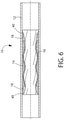
- Fig. 6 shows a stator 10 with the disk stack 14 bonded to the support rings 18 and the outer housing tube 12, and an inner lining 40 bonded to the disk stack, the support rings and the tube.
- An exemplary method for manufacturing the laminated stator includes the following steps with reference to the process flow chart illustrated in Fig. 7 .
- the disks 16 are received and inspected at Step S10, the disks are placed in proper configuration at Step S20.
- the alignment core tooling is partially assembled and the disks are stacked about it and placed in compression with compression springs to keep the disk stack tight as the alignment tooling is fully assembled.
- An exemplary compression spring resembles a cupped washer, with a hole in its center for sliding the spring over a portion of the tooling, where the spring is preferably placed either immediately before or after the pressure cap.
- a threaded nut aligned with the end of the tooling is tightened to compress the spring and transfer that compression load to the disk stack and keep the disk stack tight.
- the disk stack 14 is bonded together, for example, by running weld beads down the length of the disk stack 14 or by brazing the stack together.
- Step S40 support rings 18 are received and inspected to confirm that the inner diameter of the support ring matches the maximum inner diameter of the disk stack.
- the support rings 18 are bonded ( e.g. , welded, brazed, mechanically, chemically) concentrically to the disk at the ends of the disk stack 14, at Step S50, so that the support rings and the disk stack have the same central axis with the inner diameter of the support rings aligned with the maximum inner diameter of the disks.
- completion of the Step S50 provides a bonded stator of the combined disk stack and support ring assembly. The strength and durability of the bonded stator may be increased by insertion of the stator into the housing tube 12 as discussed in greater detail below.
- the tube may be measured, in particular for its internal diameter. From this measurement, the required outer diameter of the disk stack and support rings is confirmed at Step S70 for optimal fitting therebetween, as would readily be understood by a skilled artisan.
- the optimal fitting may require that the outer diameter of the bonded stator is slightly less than, equal to, or slightly larger than the inner diameter of the tube based on the materials of the bonded stator and tube, and the use of heat or lubricants. If needed, the disk stack is machined, polished or ground to the desired outer diameter at Step S80.
- the compression springs are removed, the pilot cap put on the alignment core, and the assembly is machined, polished or ground to the desired outer diameter if required.
- the core of the tube may be resized to an inner diameter desired for attachment to the bonded stator.
- the tube 12 is sized ( e.g ., faced to length) and chamfered.
- the tube is then prepared for stack insertion at Step S100.
- the bonded stator is inserted into the tube.
- a hydraulic ram or some other pushing/pulling tool can be used, preferably with the alignment assembly 30 to aid in inserting the bonded stator into the tube.
- the bonded stator is then bonded to the tube at Step S120.
- apertures or channels for plug welding may be milled through the tube wall and then the disk stack may be plug welded to the tube.
- the alignment assembly 30 may be removed from the bonded stator and tube assembly before or after Step S120. Removal of the alignment assembly is preferred after the bonding step since the alignment assembly may help stabilize the bonded stack during Step S120.
- the tube assembly (e.g ., bonded housing tube, disk stack and support rings) is then inspected at Step S130. If desired, an inner elastomeric lining 18 may be formed in the tube assembly at Step S140. For example, the lining material may be injected into the tube assembly and then placed in an autoclave to cure.
- the disks are preferably formed in such a way as to leave a helical passage open down the length of the stator which can be used for fluid bypass, control runs, sensor runs or any other operation that would be aided by such a passageway.
- the lobed disks are stacked with a small angular difference between each disk and the disks to either side of it, which may produce a surface that is shaped like a saw tooth from the perspective of a rotor. In addition to the labyrinth seal provided by this profile, this surface also provides advantages for bonding to an inner lining.
Landscapes
- Engineering & Computer Science (AREA)
- Mechanical Engineering (AREA)
- General Engineering & Computer Science (AREA)
- Manufacture Of Motors, Generators (AREA)
- Connection Of Motors, Electrical Generators, Mechanical Devices, And The Like (AREA)
- Gear Transmission (AREA)
Claims (15)
- Stator (10) pour un dispositif d'engrenage hélicoïdal, comprenant :une pluralité de disques (16) rigides empilés ensemble et définissant une chambre à convolutions hélicoïdales (22) allongée, chacun desdits disques (16) rigides ayant une surface intérieure avec des lobes (20) s'étendant radialement définissant une ouverture centrale, lesdits disques (16) rigides étant alignés concentriquement face à face dans une relation d'empilement hélicoïdal les uns avec les autres, chaque disque (16) étant tourné par rapport à un disque adjacent desdits disques (16) rigides progressivement sur une longueur dudit empilement de disques (14) dans une direction de rotation pour définir une chambre à convolutions hélicoïdales (22) allongée ;un élément de liaison fixé de manière fixe auxdits disques (16) rigides pour lier lesdits disques (16) rigides ensemble sous forme dudit empilement de disques (14) ; etune pluralité d'anneaux (18) de support rigides fixés de manière fixe audit empilement de disques (14), lesdits anneaux (18) comportant un premier anneau et un deuxième anneau (18), lesdits premier et deuxième anneaux (18) étant ajustés concentriquement à des extrémités opposées dudit empilement de disques (14) contre les disques (16) rigides d'extrémité dudit empilement de disques (14), lesdits anneaux (18) étant dimensionnés avec un diamètre intérieur sensiblement égal au diamètre principal de l'ouverture centrale définie par les lobes (20) s'étendant radialement desdits disques (16) rigides et lesdits anneaux supportant un rotor (24) disposés avec nutation dans ladite chambre à convolutions hélicoïdales (22) allongée par contact avec le rotor (24),caractérisé en ce quelesdits anneaux (18) de support ont une largeur axiale qui est supérieure à une largeur axiale (W) de chacun desdits disques (16) rigides, etledit élément de liaison comporte un tube (12), ledit tube (12) logeant ledit empilement de disques (14) et lesdits anneaux (18) de support rigides entièrement dans ledit tube (12).
- Stator selon la revendication 1, comprenant en outre lesdits disques (16) rigides qui sont des disques métalliques.
- Stator selon la revendication 2, comprenant en outre lesdits anneaux (18) de support rigides qui sont des anneaux de support métalliques.
- Stator selon la revendication 1, comprenant en outre lesdits anneaux (18) de support rigides qui sont des anneaux de support métalliques annulaires.
- Stator selon la revendication 1, comprenant en outre ledit empilement de disques (14) qui a une surface en dents de scie qui, pendant une communication avec nutation avec le rotor (24), fournit un joint à labyrinthe entre eux.
- Stator selon la revendication 1, dans lequel ledit empilement de disques (14) et lesdits anneaux (18) de support rigides sont liés à une surface intérieure dudit tube (12).
- Stator selon la revendication 1, dans lequel ledit empilement de disques (14) et lesdits anneaux (18) de support rigides sont fixés mécaniquement audit tube (12).
- Stator selon la revendication 1, dans lequel lesdits premier et deuxième anneaux (18) sont liés à des disques (16) rigides d'extrémité respectifs dudit empilement de disques (14).
- Stator selon la revendication 1, comprenant en outre un revêtement interne fixé à la surface intérieure des disques (16) rigides dans la chambre à convolutions hélicoïdales (22).
- Procédé de réalisation d'un stator (10) pour un dispositif d'engrenage hélicoïdal, le procédé comprenant :l'empilement d'une pluralité de disques (16) rigides dans une relation d'empilement alignée face à face les uns avec les autres, chaque disque étant tourné par rapport aux disques (16) adjacents suivants progressivement sur la longueur des disques (16) alignés dans une direction de rotation pour définir une chambre à convolutions hélicoïdales (22) allongée, chacun desdits disques (16) définissant en section transversale une ouverture définissant des lobes (20) s'étendant radialement correspondant à la taille et à la forme d'un rotor (24) ;la fixation des disques (16) rigides ensemble pour réaliser un empilement de disques (14) liés ;le couplage d'un premier anneau (18) de support rigide concentriquement à un disque rigide à une première extrémité de l'empilement de disques (14) ; etle couplage d'un deuxième anneau (18) de support rigide concentriquement à un disque rigide à une deuxième extrémité de l'empilement de disques (14) opposée à la première extrémité, les premier et deuxième anneaux (18) étant dimensionnés avec un diamètre intérieur sensiblement égal au diamètre principal de l'ouverture centrale définie par les lobes (20) s'étendant radialement desdits disques (16) rigides et lesdits anneaux (18) supportant un rotor (24) disposé avec nutation dans ladite chambre à convolutions hélicoïdales (22) allongée par contact avec le rotor (24),caractérisé en ce quele procédé comporte en outre l'insertion des premier et deuxième anneaux (18) et de l'empilement de disques (14) entièrement dans un tube (12),dans lequel les premier et deuxième anneaux (18) ont chacun une épaisseur axiale qui est supérieure à une épaisseur axiale de chacun desdits disques (16) rigides.
- Procédé selon la revendication 10, dans lequel l'étape de fixation des disques (16) rigides ensemble comporte la liaison de l'empilement de disques (14) au tube (12) pour devenir l'ensemble rigide.
- Procédé selon la revendication 11, comprenant en outre
la liaison des premier et deuxième anneaux (18) au tube (12) et à l'empilement de disques (14) pour devenir une structure monolithique. - Procédé selon la revendication 10, comprenant en outre la liaison des premier et deuxième anneaux (18) à l'empilement de disques (14) pour devenir une structure monolithique.
- Procédé selon la revendication 10, comprenant en outre la formation de l'empilement de disques (14) avec une surface de paroi intérieure en dents de scie qui, pendant une communication avec nutation avec le rotor (24) fournit un joint à labyrinthe entre eux.
- Procédé selon la revendication 10, comprenant en outre la formation d'un revêtement interne dans la chambre à convolutions hélicoïdales (22).
Applications Claiming Priority (2)
| Application Number | Priority Date | Filing Date | Title |
|---|---|---|---|
| US13/675,668 US8967985B2 (en) | 2012-11-13 | 2012-11-13 | Metal disk stacked stator with circular rigid support rings |
| PCT/US2013/068707 WO2014078145A2 (fr) | 2012-11-13 | 2013-11-06 | Stators métalliques |
Publications (2)
| Publication Number | Publication Date |
|---|---|
| EP2920467A2 EP2920467A2 (fr) | 2015-09-23 |
| EP2920467B1 true EP2920467B1 (fr) | 2022-03-09 |
Family
ID=49585676
Family Applications (1)
| Application Number | Title | Priority Date | Filing Date |
|---|---|---|---|
| EP13792223.3A Active EP2920467B1 (fr) | 2012-11-13 | 2013-11-06 | Stators métalliques |
Country Status (6)
| Country | Link |
|---|---|
| US (1) | US8967985B2 (fr) |
| EP (1) | EP2920467B1 (fr) |
| AU (1) | AU2013345132A1 (fr) |
| BR (1) | BR112015010885A2 (fr) |
| CA (1) | CA2889612C (fr) |
| WO (1) | WO2014078145A2 (fr) |
Families Citing this family (15)
| Publication number | Priority date | Publication date | Assignee | Title |
|---|---|---|---|---|
| US9133841B2 (en) * | 2013-04-11 | 2015-09-15 | Cameron International Corporation | Progressing cavity stator with metal plates having apertures with englarged ends |
| US20150122549A1 (en) * | 2013-11-05 | 2015-05-07 | Baker Hughes Incorporated | Hydraulic tools, drilling systems including hydraulic tools, and methods of using hydraulic tools |
| US9850897B2 (en) | 2013-12-30 | 2017-12-26 | Cameron International Corporation | Progressing cavity stator with gas breakout port |
| WO2015123288A2 (fr) * | 2014-02-12 | 2015-08-20 | Roper Pump Company | Moteur hybride élastomère/métal sur métal |
| USD777670S1 (en) | 2015-05-04 | 2017-01-31 | Penn United Technologies, Inc. | Stator laminate |
| US11268607B1 (en) * | 2016-02-17 | 2022-03-08 | Helix Linear Technologies | Lead screw nuts having threads formed from different materials |
| US10662950B2 (en) | 2016-10-31 | 2020-05-26 | Roper Pump Company | Progressing cavity device with cutter disks |
| CA2961629A1 (fr) | 2017-03-22 | 2018-09-22 | Infocus Energy Services Inc. | Systemes, dispositifs, assemblages d'alesage et methodes d'utilisation associees |
| US10968699B2 (en) | 2017-02-06 | 2021-04-06 | Roper Pump Company | Lobed rotor with circular section for fluid-driving apparatus |
| EP3382203B1 (fr) * | 2017-03-30 | 2024-05-15 | Roper Pump Company LLC | Pompe à cavité progressive avec gaine de chauffage intégrée |
| US11532961B2 (en) * | 2018-09-21 | 2022-12-20 | Steering Solutions Ip Holding Corporation | Pole lobed rotor core |
| WO2020150082A1 (fr) * | 2019-01-18 | 2020-07-23 | Nov Process And Flow Technologies Us, Inc. | Pompe à cavité progressive métal-métal composite |
| CN110919306B (zh) * | 2019-11-27 | 2021-09-10 | 丽水学院 | 嵌芯青铜涡轮坯加工制造工艺 |
| US11655815B2 (en) | 2019-12-13 | 2023-05-23 | Roper Pump Company, Llc | Semi-rigid stator |
| CA3115512C (fr) | 2020-04-21 | 2023-08-22 | Roper Pump Company | Stator a interieur modulaire |
Family Cites Families (24)
| Publication number | Priority date | Publication date | Assignee | Title |
|---|---|---|---|---|
| US1892217A (en) | 1930-05-13 | 1932-12-27 | Moineau Rene Joseph Louis | Gear mechanism |
| US2527673A (en) | 1947-02-28 | 1950-10-31 | Robbins & Myers | Internal helical gear pump |
| GB1238236A (fr) | 1968-09-16 | 1971-07-07 | ||
| US3771906A (en) | 1972-06-05 | 1973-11-13 | Robbins & Myers | Temperature control of stator/rotor fit in helical gear pumps |
| US3975121A (en) * | 1973-11-14 | 1976-08-17 | Smith International, Inc. | Wafer elements for progressing cavity stators |
| US3975120A (en) | 1973-11-14 | 1976-08-17 | Smith International, Inc. | Wafer elements for progressing cavity stators |
| NL7713716A (nl) | 1977-03-19 | 1978-09-21 | Streicher Foerdertech | Excenterschijvenpomp. |
| DE2712121A1 (de) * | 1977-03-19 | 1978-09-28 | Streicher Foerdertech | Exzenterschneckenpumpe |
| US4144001A (en) * | 1977-03-29 | 1979-03-13 | Fordertechnik Streicher Gmbh | Eccentric worm pump with annular wearing elements |
| US5171138A (en) | 1990-12-20 | 1992-12-15 | Drilex Systems, Inc. | Composite stator construction for downhole drilling motors |
| DE4134853C1 (fr) * | 1991-05-22 | 1992-11-12 | Netzsch-Mohnopumpen Gmbh, 8264 Waldkraiburg, De | |
| US5832604A (en) * | 1995-09-08 | 1998-11-10 | Hydro-Drill, Inc. | Method of manufacturing segmented stators for helical gear pumps and motors |
| DE19548853A1 (de) | 1995-12-27 | 1997-07-03 | Abb Research Ltd | Kegelbrenner |
| US5807087A (en) * | 1997-03-21 | 1998-09-15 | Tarby, Inc. | Stator assembly for a progressing cavity pump |
| US6241494B1 (en) | 1998-09-18 | 2001-06-05 | Schlumberger Technology Company | Non-elastomeric stator and downhole drilling motors incorporating same |
| DE10207483C1 (de) | 2002-02-22 | 2003-06-18 | Netzsch Mohnopumpen Gmbh | Exzenterschneckenpumpe |
| DE10243674B3 (de) | 2002-09-20 | 2004-04-01 | Netzsch-Mohnopumpen Gmbh | Exzenterschneckenpumpe mit Reservestator |
| DE102005042559A1 (de) | 2005-09-08 | 2007-03-15 | Netzsch-Mohnopumpen Gmbh | Statorsystem |
| CN101796301B (zh) | 2007-08-17 | 2013-05-15 | 西派克有限公司 | 设有分体型定子的偏心螺杆泵 |
| US20100284843A1 (en) | 2009-05-05 | 2010-11-11 | Jaeger Sebastian | Stator for an eccentric screw pump or an eccentric screw motor and method of producing a stator |
| US20100284842A1 (en) * | 2009-05-05 | 2010-11-11 | Sebastian Jager | Method of producing a stator segment for a segmented stator of an eccentric screw pump |
| GB2481226A (en) * | 2010-06-16 | 2011-12-21 | Nat Oilwell Varco Lp | Stator for a progressive cavity (PC) pump or motor |
| DE102010037440B4 (de) | 2010-09-09 | 2014-11-27 | Seepex Gmbh | Exzenterschneckenpumpe |
| US8672656B2 (en) | 2010-12-20 | 2014-03-18 | Robbins & Myers Energy Systems L.P. | Progressing cavity pump/motor |
-
2012
- 2012-11-13 US US13/675,668 patent/US8967985B2/en active Active
-
2013
- 2013-11-06 BR BR112015010885A patent/BR112015010885A2/pt not_active IP Right Cessation
- 2013-11-06 WO PCT/US2013/068707 patent/WO2014078145A2/fr not_active Ceased
- 2013-11-06 CA CA2889612A patent/CA2889612C/fr active Active
- 2013-11-06 AU AU2013345132A patent/AU2013345132A1/en not_active Abandoned
- 2013-11-06 EP EP13792223.3A patent/EP2920467B1/fr active Active
Also Published As
| Publication number | Publication date |
|---|---|
| CA2889612C (fr) | 2019-09-10 |
| EP2920467A2 (fr) | 2015-09-23 |
| US8967985B2 (en) | 2015-03-03 |
| WO2014078145A3 (fr) | 2014-08-28 |
| BR112015010885A2 (pt) | 2017-10-03 |
| AU2013345132A1 (en) | 2015-05-14 |
| CA2889612A1 (fr) | 2014-05-22 |
| US20140134029A1 (en) | 2014-05-15 |
| WO2014078145A2 (fr) | 2014-05-22 |
Similar Documents
| Publication | Publication Date | Title |
|---|---|---|
| EP2920467B1 (fr) | Stators métalliques | |
| US10458240B2 (en) | Hybrid elastomer/metal on metal motor | |
| CA2535687C (fr) | Stator a cavite en mouvement comprenant au moins une section longitudinale moulee | |
| US11421693B2 (en) | Progressing cavity device with cutter disks | |
| CA2794501C (fr) | Stator degage pour moteur volumetrique | |
| JP5634715B2 (ja) | コンプライアントプレートシール組立体の製造方法 | |
| WO2001044615A2 (fr) | Stator composite destine a des moteurs de forage et son procede de construction | |
| EP1693571A2 (fr) | Stator élastomère multi-couche de pompe à cavité progressive | |
| CA2712364C (fr) | Stator pour pompe a vis excentree ou pour moteur a vis excentree fonctionnant selon le principe de moineau | |
| JP4183015B1 (ja) | シングルスクリュー圧縮機およびその組立方法 | |
| US20060182643A1 (en) | Progressing cavity stator having a plurality of cast longitudinal sections | |
| CA3085865C (fr) | Rotor a lobes dote d'une section circulaire destinee a un appareil d'entrainement de fluide | |
| US11655815B2 (en) | Semi-rigid stator | |
| US7621167B2 (en) | Method of forming a rotary device | |
| US20260071621A1 (en) | Progressive cavity fluid pump and associated methods | |
| EP3149334B1 (fr) | Plaque de pression et plaque à orifice intégrées pour pompe |
Legal Events
| Date | Code | Title | Description |
|---|---|---|---|
| PUAI | Public reference made under article 153(3) epc to a published international application that has entered the european phase |
Free format text: ORIGINAL CODE: 0009012 |
|
| 17P | Request for examination filed |
Effective date: 20150429 |
|
| AK | Designated contracting states |
Kind code of ref document: A2 Designated state(s): AL AT BE BG CH CY CZ DE DK EE ES FI FR GB GR HR HU IE IS IT LI LT LU LV MC MK MT NL NO PL PT RO RS SE SI SK SM TR |
|
| AX | Request for extension of the european patent |
Extension state: BA ME |
|
| RIN1 | Information on inventor provided before grant (corrected) |
Inventor name: PURCELL, JOHN, EUGENE Inventor name: ANDERSON, TYSON, BENTLEY Inventor name: RIVARD, ZACHARIAH, PAUL Inventor name: COGHLAN, EDMOND, III |
|
| DAX | Request for extension of the european patent (deleted) | ||
| STAA | Information on the status of an ep patent application or granted ep patent |
Free format text: STATUS: EXAMINATION IS IN PROGRESS |
|
| 17Q | First examination report despatched |
Effective date: 20161219 |
|
| GRAP | Despatch of communication of intention to grant a patent |
Free format text: ORIGINAL CODE: EPIDOSNIGR1 |
|
| STAA | Information on the status of an ep patent application or granted ep patent |
Free format text: STATUS: GRANT OF PATENT IS INTENDED |
|
| INTG | Intention to grant announced |
Effective date: 20210930 |
|
| RIN1 | Information on inventor provided before grant (corrected) |
Inventor name: RIVARD, ZACHARIAH, PAUL Inventor name: PURCELL, JOHN, EUGENE Inventor name: ANDERSON, TYSON, BENTLEY Inventor name: COGHLAN, EDMOND, III |
|
| GRAS | Grant fee paid |
Free format text: ORIGINAL CODE: EPIDOSNIGR3 |
|
| GRAA | (expected) grant |
Free format text: ORIGINAL CODE: 0009210 |
|
| STAA | Information on the status of an ep patent application or granted ep patent |
Free format text: STATUS: THE PATENT HAS BEEN GRANTED |
|
| AK | Designated contracting states |
Kind code of ref document: B1 Designated state(s): AL AT BE BG CH CY CZ DE DK EE ES FI FR GB GR HR HU IE IS IT LI LT LU LV MC MK MT NL NO PL PT RO RS SE SI SK SM TR |
|
| REG | Reference to a national code |
Ref country code: GB Ref legal event code: FG4D |
|
| REG | Reference to a national code |
Ref country code: CH Ref legal event code: EP Ref country code: AT Ref legal event code: REF Ref document number: 1474351 Country of ref document: AT Kind code of ref document: T Effective date: 20220315 |
|
| REG | Reference to a national code |
Ref country code: DE Ref legal event code: R096 Ref document number: 602013081081 Country of ref document: DE |
|
| REG | Reference to a national code |
Ref country code: IE Ref legal event code: FG4D |
|
| REG | Reference to a national code |
Ref country code: NL Ref legal event code: FP |
|
| REG | Reference to a national code |
Ref country code: LT Ref legal event code: MG9D |
|
| PG25 | Lapsed in a contracting state [announced via postgrant information from national office to epo] |
Ref country code: SE Free format text: LAPSE BECAUSE OF FAILURE TO SUBMIT A TRANSLATION OF THE DESCRIPTION OR TO PAY THE FEE WITHIN THE PRESCRIBED TIME-LIMIT Effective date: 20220309 Ref country code: RS Free format text: LAPSE BECAUSE OF FAILURE TO SUBMIT A TRANSLATION OF THE DESCRIPTION OR TO PAY THE FEE WITHIN THE PRESCRIBED TIME-LIMIT Effective date: 20220309 Ref country code: NO Free format text: LAPSE BECAUSE OF FAILURE TO SUBMIT A TRANSLATION OF THE DESCRIPTION OR TO PAY THE FEE WITHIN THE PRESCRIBED TIME-LIMIT Effective date: 20220609 Ref country code: LT Free format text: LAPSE BECAUSE OF FAILURE TO SUBMIT A TRANSLATION OF THE DESCRIPTION OR TO PAY THE FEE WITHIN THE PRESCRIBED TIME-LIMIT Effective date: 20220309 Ref country code: HR Free format text: LAPSE BECAUSE OF FAILURE TO SUBMIT A TRANSLATION OF THE DESCRIPTION OR TO PAY THE FEE WITHIN THE PRESCRIBED TIME-LIMIT Effective date: 20220309 Ref country code: BG Free format text: LAPSE BECAUSE OF FAILURE TO SUBMIT A TRANSLATION OF THE DESCRIPTION OR TO PAY THE FEE WITHIN THE PRESCRIBED TIME-LIMIT Effective date: 20220609 |
|
| REG | Reference to a national code |
Ref country code: AT Ref legal event code: MK05 Ref document number: 1474351 Country of ref document: AT Kind code of ref document: T Effective date: 20220309 |
|
| PG25 | Lapsed in a contracting state [announced via postgrant information from national office to epo] |
Ref country code: LV Free format text: LAPSE BECAUSE OF FAILURE TO SUBMIT A TRANSLATION OF THE DESCRIPTION OR TO PAY THE FEE WITHIN THE PRESCRIBED TIME-LIMIT Effective date: 20220309 Ref country code: GR Free format text: LAPSE BECAUSE OF FAILURE TO SUBMIT A TRANSLATION OF THE DESCRIPTION OR TO PAY THE FEE WITHIN THE PRESCRIBED TIME-LIMIT Effective date: 20220610 Ref country code: FI Free format text: LAPSE BECAUSE OF FAILURE TO SUBMIT A TRANSLATION OF THE DESCRIPTION OR TO PAY THE FEE WITHIN THE PRESCRIBED TIME-LIMIT Effective date: 20220309 |
|
| PG25 | Lapsed in a contracting state [announced via postgrant information from national office to epo] |
Ref country code: SM Free format text: LAPSE BECAUSE OF FAILURE TO SUBMIT A TRANSLATION OF THE DESCRIPTION OR TO PAY THE FEE WITHIN THE PRESCRIBED TIME-LIMIT Effective date: 20220309 Ref country code: SK Free format text: LAPSE BECAUSE OF FAILURE TO SUBMIT A TRANSLATION OF THE DESCRIPTION OR TO PAY THE FEE WITHIN THE PRESCRIBED TIME-LIMIT Effective date: 20220309 Ref country code: RO Free format text: LAPSE BECAUSE OF FAILURE TO SUBMIT A TRANSLATION OF THE DESCRIPTION OR TO PAY THE FEE WITHIN THE PRESCRIBED TIME-LIMIT Effective date: 20220309 Ref country code: PT Free format text: LAPSE BECAUSE OF FAILURE TO SUBMIT A TRANSLATION OF THE DESCRIPTION OR TO PAY THE FEE WITHIN THE PRESCRIBED TIME-LIMIT Effective date: 20220711 Ref country code: ES Free format text: LAPSE BECAUSE OF FAILURE TO SUBMIT A TRANSLATION OF THE DESCRIPTION OR TO PAY THE FEE WITHIN THE PRESCRIBED TIME-LIMIT Effective date: 20220309 Ref country code: EE Free format text: LAPSE BECAUSE OF FAILURE TO SUBMIT A TRANSLATION OF THE DESCRIPTION OR TO PAY THE FEE WITHIN THE PRESCRIBED TIME-LIMIT Effective date: 20220309 Ref country code: CZ Free format text: LAPSE BECAUSE OF FAILURE TO SUBMIT A TRANSLATION OF THE DESCRIPTION OR TO PAY THE FEE WITHIN THE PRESCRIBED TIME-LIMIT Effective date: 20220309 Ref country code: AT Free format text: LAPSE BECAUSE OF FAILURE TO SUBMIT A TRANSLATION OF THE DESCRIPTION OR TO PAY THE FEE WITHIN THE PRESCRIBED TIME-LIMIT Effective date: 20220309 |
|
| PG25 | Lapsed in a contracting state [announced via postgrant information from national office to epo] |
Ref country code: PL Free format text: LAPSE BECAUSE OF FAILURE TO SUBMIT A TRANSLATION OF THE DESCRIPTION OR TO PAY THE FEE WITHIN THE PRESCRIBED TIME-LIMIT Effective date: 20220309 Ref country code: IS Free format text: LAPSE BECAUSE OF FAILURE TO SUBMIT A TRANSLATION OF THE DESCRIPTION OR TO PAY THE FEE WITHIN THE PRESCRIBED TIME-LIMIT Effective date: 20220709 Ref country code: AL Free format text: LAPSE BECAUSE OF FAILURE TO SUBMIT A TRANSLATION OF THE DESCRIPTION OR TO PAY THE FEE WITHIN THE PRESCRIBED TIME-LIMIT Effective date: 20220309 |
|
| REG | Reference to a national code |
Ref country code: DE Ref legal event code: R081 Ref document number: 602013081081 Country of ref document: DE Owner name: ROPER PUMP COMPANY LLC (N.D.GES.D. STAATES DEL, US Free format text: FORMER OWNER: ROPER PUMP COMPANY, COMMERCE, GA, US |
|
| REG | Reference to a national code |
Ref country code: DE Ref legal event code: R097 Ref document number: 602013081081 Country of ref document: DE |
|
| PLBE | No opposition filed within time limit |
Free format text: ORIGINAL CODE: 0009261 |
|
| STAA | Information on the status of an ep patent application or granted ep patent |
Free format text: STATUS: NO OPPOSITION FILED WITHIN TIME LIMIT |
|
| PG25 | Lapsed in a contracting state [announced via postgrant information from national office to epo] |
Ref country code: DK Free format text: LAPSE BECAUSE OF FAILURE TO SUBMIT A TRANSLATION OF THE DESCRIPTION OR TO PAY THE FEE WITHIN THE PRESCRIBED TIME-LIMIT Effective date: 20220309 |
|
| 26N | No opposition filed |
Effective date: 20221212 |
|
| PG25 | Lapsed in a contracting state [announced via postgrant information from national office to epo] |
Ref country code: SI Free format text: LAPSE BECAUSE OF FAILURE TO SUBMIT A TRANSLATION OF THE DESCRIPTION OR TO PAY THE FEE WITHIN THE PRESCRIBED TIME-LIMIT Effective date: 20220309 |
|
| PG25 | Lapsed in a contracting state [announced via postgrant information from national office to epo] |
Ref country code: MC Free format text: LAPSE BECAUSE OF FAILURE TO SUBMIT A TRANSLATION OF THE DESCRIPTION OR TO PAY THE FEE WITHIN THE PRESCRIBED TIME-LIMIT Effective date: 20220309 |
|
| REG | Reference to a national code |
Ref country code: CH Ref legal event code: PL |
|
| P01 | Opt-out of the competence of the unified patent court (upc) registered |
Effective date: 20230527 |
|
| REG | Reference to a national code |
Ref country code: BE Ref legal event code: MM Effective date: 20221130 |
|
| PG25 | Lapsed in a contracting state [announced via postgrant information from national office to epo] |
Ref country code: LI Free format text: LAPSE BECAUSE OF NON-PAYMENT OF DUE FEES Effective date: 20221130 Ref country code: IT Free format text: LAPSE BECAUSE OF FAILURE TO SUBMIT A TRANSLATION OF THE DESCRIPTION OR TO PAY THE FEE WITHIN THE PRESCRIBED TIME-LIMIT Effective date: 20220309 Ref country code: CH Free format text: LAPSE BECAUSE OF NON-PAYMENT OF DUE FEES Effective date: 20221130 |
|
| PG25 | Lapsed in a contracting state [announced via postgrant information from national office to epo] |
Ref country code: LU Free format text: LAPSE BECAUSE OF NON-PAYMENT OF DUE FEES Effective date: 20221106 |
|
| PG25 | Lapsed in a contracting state [announced via postgrant information from national office to epo] |
Ref country code: IE Free format text: LAPSE BECAUSE OF NON-PAYMENT OF DUE FEES Effective date: 20221106 |
|
| PG25 | Lapsed in a contracting state [announced via postgrant information from national office to epo] |
Ref country code: BE Free format text: LAPSE BECAUSE OF NON-PAYMENT OF DUE FEES Effective date: 20221130 |
|
| PG25 | Lapsed in a contracting state [announced via postgrant information from national office to epo] |
Ref country code: HU Free format text: LAPSE BECAUSE OF FAILURE TO SUBMIT A TRANSLATION OF THE DESCRIPTION OR TO PAY THE FEE WITHIN THE PRESCRIBED TIME-LIMIT; INVALID AB INITIO Effective date: 20131106 |
|
| PG25 | Lapsed in a contracting state [announced via postgrant information from national office to epo] |
Ref country code: CY Free format text: LAPSE BECAUSE OF FAILURE TO SUBMIT A TRANSLATION OF THE DESCRIPTION OR TO PAY THE FEE WITHIN THE PRESCRIBED TIME-LIMIT Effective date: 20220309 |
|
| PG25 | Lapsed in a contracting state [announced via postgrant information from national office to epo] |
Ref country code: MK Free format text: LAPSE BECAUSE OF FAILURE TO SUBMIT A TRANSLATION OF THE DESCRIPTION OR TO PAY THE FEE WITHIN THE PRESCRIBED TIME-LIMIT Effective date: 20220309 |
|
| PG25 | Lapsed in a contracting state [announced via postgrant information from national office to epo] |
Ref country code: MT Free format text: LAPSE BECAUSE OF FAILURE TO SUBMIT A TRANSLATION OF THE DESCRIPTION OR TO PAY THE FEE WITHIN THE PRESCRIBED TIME-LIMIT Effective date: 20220309 |
|
| PG25 | Lapsed in a contracting state [announced via postgrant information from national office to epo] |
Ref country code: TR Free format text: LAPSE BECAUSE OF FAILURE TO SUBMIT A TRANSLATION OF THE DESCRIPTION OR TO PAY THE FEE WITHIN THE PRESCRIBED TIME-LIMIT Effective date: 20220309 |
|
| PGFP | Annual fee paid to national office [announced via postgrant information from national office to epo] |
Ref country code: NL Payment date: 20251119 Year of fee payment: 13 |
|
| PGFP | Annual fee paid to national office [announced via postgrant information from national office to epo] |
Ref country code: DE Payment date: 20251118 Year of fee payment: 13 |
|
| PGFP | Annual fee paid to national office [announced via postgrant information from national office to epo] |
Ref country code: GB Payment date: 20251125 Year of fee payment: 13 |
|
| PGFP | Annual fee paid to national office [announced via postgrant information from national office to epo] |
Ref country code: FR Payment date: 20251125 Year of fee payment: 13 |