EP2920689B1 - Systèmes de stockage efficaces à haute disponibilité - Google Patents
Systèmes de stockage efficaces à haute disponibilité Download PDFInfo
- Publication number
- EP2920689B1 EP2920689B1 EP13867762.0A EP13867762A EP2920689B1 EP 2920689 B1 EP2920689 B1 EP 2920689B1 EP 13867762 A EP13867762 A EP 13867762A EP 2920689 B1 EP2920689 B1 EP 2920689B1
- Authority
- EP
- European Patent Office
- Prior art keywords
- data
- server
- submatrix
- data block
- row
- Prior art date
- Legal status (The legal status is an assumption and is not a legal conclusion. Google has not performed a legal analysis and makes no representation as to the accuracy of the status listed.)
- Active
Links
Images


Classifications
-
- H—ELECTRICITY
- H04—ELECTRIC COMMUNICATION TECHNIQUE
- H04L—TRANSMISSION OF DIGITAL INFORMATION, e.g. TELEGRAPHIC COMMUNICATION
- H04L67/00—Network arrangements or protocols for supporting network services or applications
- H04L67/01—Protocols
- H04L67/10—Protocols in which an application is distributed across nodes in the network
-
- H—ELECTRICITY
- H04—ELECTRIC COMMUNICATION TECHNIQUE
- H04L—TRANSMISSION OF DIGITAL INFORMATION, e.g. TELEGRAPHIC COMMUNICATION
- H04L67/00—Network arrangements or protocols for supporting network services or applications
- H04L67/01—Protocols
- H04L67/10—Protocols in which an application is distributed across nodes in the network
- H04L67/1097—Protocols in which an application is distributed across nodes in the network for distributed storage of data in networks, e.g. transport arrangements for network file system [NFS], storage area networks [SAN] or network attached storage [NAS]
-
- G—PHYSICS
- G06—COMPUTING OR CALCULATING; COUNTING
- G06F—ELECTRIC DIGITAL DATA PROCESSING
- G06F11/00—Error detection; Error correction; Monitoring
- G06F11/07—Responding to the occurrence of a fault, e.g. fault tolerance
- G06F11/08—Error detection or correction by redundancy in data representation, e.g. by using checking codes
- G06F11/10—Adding special bits or symbols to the coded information, e.g. parity check, casting out 9's or 11's
- G06F11/1076—Parity data used in redundant arrays of independent storages, e.g. in RAID systems
- G06F11/1092—Rebuilding, e.g. when physically replacing a failing disk
-
- H—ELECTRICITY
- H04—ELECTRIC COMMUNICATION TECHNIQUE
- H04L—TRANSMISSION OF DIGITAL INFORMATION, e.g. TELEGRAPHIC COMMUNICATION
- H04L67/00—Network arrangements or protocols for supporting network services or applications
- H04L67/01—Protocols
- H04L67/10—Protocols in which an application is distributed across nodes in the network
- H04L67/104—Peer-to-peer [P2P] networks
- H04L67/1074—Peer-to-peer [P2P] networks for supporting data block transmission mechanisms
- H04L67/1078—Resource delivery mechanisms
- H04L67/108—Resource delivery mechanisms characterised by resources being split in blocks or fragments
-
- H—ELECTRICITY
- H04—ELECTRIC COMMUNICATION TECHNIQUE
- H04L—TRANSMISSION OF DIGITAL INFORMATION, e.g. TELEGRAPHIC COMMUNICATION
- H04L69/00—Network arrangements, protocols or services independent of the application payload and not provided for in the other groups of this subclass
- H04L69/40—Network arrangements, protocols or services independent of the application payload and not provided for in the other groups of this subclass for recovering from a failure of a protocol instance or entity, e.g. service redundancy protocols, protocol state redundancy or protocol service redirection
-
- G—PHYSICS
- G06—COMPUTING OR CALCULATING; COUNTING
- G06F—ELECTRIC DIGITAL DATA PROCESSING
- G06F2211/00—Indexing scheme relating to details of data-processing equipment not covered by groups G06F3/00 - G06F13/00
- G06F2211/10—Indexing scheme relating to G06F11/10
- G06F2211/1002—Indexing scheme relating to G06F11/1076
- G06F2211/1009—Cache, i.e. caches used in RAID system with parity
-
- G—PHYSICS
- G06—COMPUTING OR CALCULATING; COUNTING
- G06F—ELECTRIC DIGITAL DATA PROCESSING
- G06F2211/00—Indexing scheme relating to details of data-processing equipment not covered by groups G06F3/00 - G06F13/00
- G06F2211/10—Indexing scheme relating to G06F11/10
- G06F2211/1002—Indexing scheme relating to G06F11/1076
- G06F2211/1028—Distributed, i.e. distributed RAID systems with parity
-
- G—PHYSICS
- G06—COMPUTING OR CALCULATING; COUNTING
- G06F—ELECTRIC DIGITAL DATA PROCESSING
- G06F2211/00—Indexing scheme relating to details of data-processing equipment not covered by groups G06F3/00 - G06F13/00
- G06F2211/10—Indexing scheme relating to G06F11/10
- G06F2211/1002—Indexing scheme relating to G06F11/1076
- G06F2211/105—On the fly coding, e.g. using XOR accumulators
-
- G—PHYSICS
- G06—COMPUTING OR CALCULATING; COUNTING
- G06F—ELECTRIC DIGITAL DATA PROCESSING
- G06F2211/00—Indexing scheme relating to details of data-processing equipment not covered by groups G06F3/00 - G06F13/00
- G06F2211/10—Indexing scheme relating to G06F11/10
- G06F2211/1002—Indexing scheme relating to G06F11/1076
- G06F2211/1057—Parity-multiple bits-RAID6, i.e. RAID 6 implementations
-
- Y—GENERAL TAGGING OF NEW TECHNOLOGICAL DEVELOPMENTS; GENERAL TAGGING OF CROSS-SECTIONAL TECHNOLOGIES SPANNING OVER SEVERAL SECTIONS OF THE IPC; TECHNICAL SUBJECTS COVERED BY FORMER USPC CROSS-REFERENCE ART COLLECTIONS [XRACs] AND DIGESTS
- Y10—TECHNICAL SUBJECTS COVERED BY FORMER USPC
- Y10S—TECHNICAL SUBJECTS COVERED BY FORMER USPC CROSS-REFERENCE ART COLLECTIONS [XRACs] AND DIGESTS
- Y10S707/00—Data processing: database and file management or data structures
- Y10S707/99951—File or database maintenance
- Y10S707/99952—Coherency, e.g. same view to multiple users
- Y10S707/99955—Archiving or backup
Definitions
- Data redundancy enables the availability of data in the circumstance that one or more storage nodes fail.
- Many enterprise storage systems e.g., Network Attached Storage (NAS), Storage Area Network (SAN)
- cloud storage systems e.g. Object Storage, Key Value Store
- Data redundancy may be classified into two categories: replica based and erasure coding based.
- a classical three-replica approach keeps three copies for one data content and stores them into three storage nodes, which triples the cost. When this method is applied to a distributed storage system with, for example, 100 nodes, if more than two servers fail, there may be a high probability that some of the data will become unavailable.
- Erasure coding uses the notation "N+M" to denote N data blocks and M redundancy blocks generated by the encoding of N data blocks. That is, N data blocks may be encoded to generate N+M total blocks.
- the extra cost of encoding may be defined as M/N.
- an "8+2" coding implemented in a 100 node system may still have a certain probability for data unavailability.
- WO 2012/148858 A2 relates to a system for implementing distributed RAID, comprising a plurality of data bank computers, wherein each data bank is coupled to each of one or more hosts and each of the other plurality of data banks.
- Each data bank includes a processor; a data store; a high speed memory; and a computer readable medium comprising first instructions for a distributed RAID application.
- the first instructions are executable for receiving a command corresponding to a first segment of a volume from a first host of the one or more hosts, wherein the volume and redundancy data corresponding to a RAID level implemented in conjunction with the volume are stored on each of the plurality of data banks, such that for each segment of the volume a corresponding redundancy segment comprising the redundancy data associated with that segment does not reside on the same data bank as the segment; determining if the first command is a write command and if the command is a write command storing the write command in a write cache on the high speed memory; determining a first data bank of the plurality of data banks, wherein the first data bank corresponds to the first segment; and if the first data bank is the data bank which received the command, executing the first command with respect to the first segment and if not, forwarding the first command to the first data bank.
- US 2007/245082 A1 relates to a method for organizing a storage system.
- the method comprises grouping together a number D of storage elements to form the storage system, where D is more than one; constructing a storage assignment table that comprises table entries; computing, for each of the storage elements, an available capacity that depends on constraints on the placement of redundant data within the storage system; summing the available capacities to form a total available capacity for the storage system; and assigning the table entries in the storage assignment table to the storage elements; wherein the available capacity of each of the storage elements is its effective storage capacity when used as part of the storage system; not all of the D storage elements that form the storage system have the same available capacity; and the fraction of all table entries that identify the storage elements depends upon its fraction of the total available capacity.
- the disclosure includes a server configured to form part of a data protection group, wherein the server comprises a memory, a transceiver configured to receive a request to store a data file from another device, and a processor coupled to the memory and the transceiver and configured to acquire the request to store a data file, write the data file to a container in the memory, and encode the container contents when the container becomes full to generate a plurality of encoded blocks, wherein the transceiver is further configured to distribute the plurality of encoded blocks over peer servers in the data group, wherein the server further comprises a cache, wherein the container contents forms a data block, and wherein encoding the container contents comprises: determine a size of the coding matrix, determine a size of a submatrix of the data block such that the sum of the size of the coding matrix and the size of the submatrix is smaller than the size of the cache, request that the submatrix of the data block and the
- Architectures and mechanisms are presented for storing data and recovering lost data in data storage systems employing large groups of servers.
- Methods are proposed to optimize erasure coding and decoding calculations by utilizing a single instruction multiple data (SIMD) approach, a cache-friendly improvement, instruction level parallelism, and a minimum spanning tree based optimization. Additionally, a parallel data recovery mechanism may be implemented with a reduced recovery window length.
- SIMD single instruction multiple data
- An efficient matrix calculation may enable high performance software Cauchy Reed-Solomon erasure coding and decoding at an unprecedented scale (e.g., "80+20"). Large-scale erasure coding methods and associated architectures may achieve higher data availability with decreased cost.
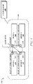
- FIG. 1 is an example of a data protection group (DPG) architecture 100 that employs erasure coding.
- the architecture 100 may comprise a plurality of storage servers 110, as well as at least one location node 130.
- the architecture 100 may be implemented in storage systems with data redundancy requirements (e.g., Network Attached Storage (NAS), object storage, and key value store).
- NAS Network Attached Storage
- the four storage servers 110 may form a DPG 105 and store the backup of data. Although only four storage servers 110 are shown for illustrative purposes, any number of servers may be used in the system.
- a container 120 may be some amount of storage (corresponding to an address space in memory) allocated by a server in a DPG 105 with a fixed size limit.
- the container 120 may store a plurality of files until it is full. Once the container 120 reaches its limit in data storage, the container 120 may be sealed and ready for erasure coding.
- the container 120 may be spread to coded blocks 125 and distributed among other servers in a DPG.
- a location node 130 may store the identifiers (IDs) or addresses of the servers along with membership information. For example, all the servers with ID 1 to 100 may be stored in one DPG. This information may be found in a location node 130, which may be a centralized or distributed repository. A location node 130 may also hold mapping information of the containers and corresponding coded blocks in a DPG.
- IDs identifiers
- a location node 130 may also hold mapping information of the containers and corresponding coded blocks in a DPG.
- a client request may arrive at one or more of the servers according to predefined protocols, including but not limited to random selection, random robin selection, and hash based load balancing selection. For instance, a request may arrive at storage Server2 110.
- the server may store the data stream into a corresponding container (e.g., container 120). Once the container has reached its limit, Server2 110 may seal container 120 and proceed with erasure coding.
- Server2 110 may run erasure coding, such as Cauchy Reed-Solomon erasure coding proposed herein, and subsequently distribute the coded blocks 125 to other peers in the same DPG (e.g. DPG 105).
- erasure coding such as Cauchy Reed-Solomon erasure coding proposed herein
- Server2 110 may use predefined rules or query a location node 130 to find other peers. After successfully spreading the coded blocks to other peers, Server2 110 may record the mapping of the coded container 120 to a location node 130. That is, Server2 110 may tell a location node 130 that it is responsible for container 120. The mapping may comprise a container ID and server ID pair sent to a location node.
- a DPG may comprise 100 servers, each with a container size limit of 80 megabytes (MB).
- the data may be divided into 1 MB blocks and distributed over 100 coded containers corresponding to the 100 servers, with, e.g., one block per server.
- the data in the container may be divided into 80 blocks, while the other 20 blocks may be a result of a redundancy checksum.
- the containers may be distributed among servers to maximize fault tolerance; however, in another aspect of the invention, multiple containers may be stored on fewer servers.
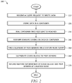
- FIG. 2 is a flowchart 200 of an example of a method for running erasure coding.
- the steps of the flowchart 200 may be implemented in a data storage system with at least one DPG, a plurality of servers, and at least one location node, such as DPG 105 comprising servers 110 and location node 130.
- the flowchart begins in block 210, in which a server (e.g., Server2 110 in FIG. 1 ) may receive data from a client request.
- the specific server may be selected according to protocols known to a person of ordinary skill in the art (including but not limited to random selection, random robin selection, and hash based load balancing selection).
- the server may store the obtained data in a corresponding container, such as container 120 in FIG.
- Incoming data may be stored until the container is full.
- the method continues in block 230, in which the server may seal the container in preparation of erasure coding.
- the server may run erasure coding, such as Cauchy Reed-Solomon erasure coding proposed herein, on the data stored in the container.
- the server may query a location node (such as location node 130) in block 250 in order to find other peer servers in the DPG.
- the server may distribute the coded blocks (e.g. coded blocks 125) obtained from erasure coding to peer servers.
- the method ends at block 270, with the server recording the mapping information of the coded blocks and server locations (e.g., container ID and server ID pairs) to the location node.
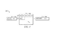
- FIG. 3 illustrates an example of a Cauchy Reed-Solomon erasure coding matrix calculation 300.
- the erasure coding calculation 300 comprises a matrix A 310, a matrix B 320, a matrix C 330, and operator (OP) 315.
- Matrix A 310 may be an index matrix with each element being binary, e.g., either a one or a zero.
- Matrix A 310 may be formed according to Cauchy Reed-Solomon coding principles as understood by a person of ordinary skill in the art.
- Matrix B 320 may represent raw data as stored in a container (e.g., container 120).
- Matrix B may be formed by dividing a container into an integer number of blocks, each of which form a sub-matrix of B.
- Sub-matrices of B are represented as bij in FIG. 3 .
- Matrix C 330 may be coded content which is the product of matrices A and B.
- OP 315 represents an operator which may be the same as the matrix multiplication, except that addition operations may be replaced by exclusive OR (XOR) operations.
- XOR exclusive OR
- XOR is a binary operation known to a personal having ordinary skill in the art, wherein if x and y are binary numbers, the result of x XOR y is one if x and y are different and zero otherwise.
- matrix B may contain raw data in a container 120 in a server 110.
- a server such as Server2 110, may divide the data into sub-matrices in matrix B.
- a coding matrix A may be applied to matrix B to obtain the encoded data in matrix C.
- Matrix A may be a predefined matrix that indicates which row of B will participate in an XOR operation.
- FIG. 4 is an architecture diagram of a server 340 suitable for implementing one or more aspects of the invention of the components disclosed herein, such as storage servers 110 or location node 130.
- the server 340 comprises a central processing unit (CPU) 354, a random access memory (RAM) 346, a secondary storage device 344, and a transceiver (or transmitter/receiver) 352 configured as shown in FIG. 4 .
- the CPU 354 comprises a processor 342, one or more registers 350 (the integer n in FIG. 4 may be any positive integer, such as a power of two), and a cache 348 configured as shown.
- the processor 342 may be implemented as one or more general purpose processors, cores (e.g., a multi-core processor), field-programmable gate arrays (FPGAs), application specific integrated circuits (ASICs), and/or digital signal processors (DSPs).
- the processor 342 may implement or be configured to perform any of the functionalities of DPGs, storage servers, or location nodes, such as all or part of the methods illustrated in flowcharts 200, 500, and 700.
- the processor 342 may be or comprise an arithmetic logic unit (ALU).
- the processor 342 may be in communication with the registers 350, cache 348, RAM 346, and secondary storage 344 at least in part to provide control of these elements.
- the secondary storage 344 typically comprises one or more disk drives or tape drives and is used for non-volatile storage of data and as an over-flow data storage device if RAM 346 is not large enough to hold all working data. Secondary storage 344 may be used to store programs that are loaded into RAM 346 when such programs are selected for execution. Access to RAM 346 is typically faster than to secondary storage 344. Fast memory components (e.g., RAM 346) may be expensive, while cheaper memory such as a hard drive (e.g., secondary storage 344) is slower. There is a tradeoff in memory when choosing memory components in terms of cost and speed. This tradeoff is further expressed in the use of cache 348 and registers 350. The registers 350 provide the fastest memory access but at the greatest cost per unit of storage. Next in the speed/cost tradeoff is cache 348, which has slower memory access than registers 350 but at lower cost per unit of storage (however, cache is faster but more expensive than RAM 346 per unit of storage).
- the cache 348 may be used to accommodate data in the CPU 354 during an erasure coding process.
- the cache 348 may store raw data and encoded data during aforementioned matrix calculations for erasure coding.
- the registers 350 may be employed to provide fast memory for the processor 342.
- the cache 348 and registers 350 in FIG. 4 may be configured to take advantage of the enhancements disclosed herein.
- the cache 348 may read from or write to any of registers 350.
- the transceiver 352 may serve as an output and/or input device of the server 340.
- the transceiver 352 may take the form of modems, modem banks, Ethernet cards, universal serial bus (USB) interface cards, serial interfaces, token ring cards, fiber distributed data interface (FDDI) cards, wireless local area network (WLAN) cards, radio transceiver cards such as code division multiple access (CDMA), global system for mobile communications (GSM), long-term evolution (LTE), worldwide interoperability for microwave access (WiMAX), and/or other air interface protocol radio transceiver cards, and other well-known network devices.
- the transceiver 352 may allow the processor 342 to communicate with an Internet, one or more intranets, one or more other servers, and/or a location node in a DPG.
- SIMD single instruction, multiple data
- Intel Streaming SIMD Extensions which may be supported by the CPU 354
- the SIMD approach may be beneficial because it allows for the processing of multiple data bits in parallel, which may be conducted by a processor, such as processor 342.
- Erasure coding may also be designed to be cache-friendly.
- matrix B 320 may be 80 MB which exceeds a CPU's on-chip cache size (e.g., 1 MB).
- Matrix C 330 may be 20 MB, and matrix A 310 may be tens of kilobytes.
- matrices A through C may be divided into blocks. The sum of the size of A and each block or sub-matrix of B (e.g., b11) may be smaller than the on-chip cache (e.g., cache 348) that the CPU accommodates.
- the width of the blocks in B may be determined by the cache line size (e.g., 16 to 256 bytes) and the size of the available registers, such as registers 350.
- the product of the two may be saved in matrix C. Thus, b11 may not need to be loaded into the CPU cache anymore.
- the intermediate results may be stored into registers temporarily and later moved to matrix C after processing the whole row.
- the first row of matrix A has three elements, denoted as a1r11, a1r12, and a1r13. These elements may indicate which rows of b11 should be added together.
- a1r11, a1r12, and a1r13 are all ones, which indicates that all three rows in B11 should XOR together (meaning an XOR between two rows may be computed and the resulted XOR'd with the third row).
- source registers e.g., registers 350
- This step can be subsequently repeated for each row of b11.
- the contents of the source registers e.g., registers 350
- an instruction level parallelism (ILP) technique may be implemented as an encoding enhancement.
- ILP as much content as possible may be loaded into all the available SIMD registers (e.g., registers 350) before performing the XOR operations.
- all or many of the rows of a data sub-matrix (such as b11 above) that are indicated as needing to be added together by matrix A could be loaded into the registers.
- An XOR of a plurality of pairs of rows may be performed in parallel (e.g., by a processor, such as processor 342). This may enable a CPU instruction level parallelism optimization because the loading and computing of each register does not interfere with each other.
- the total number of control instructions required e.g., Intel instruction set instructions, such as compare (CMP) and jump instruction table (Jxx) may be reduced by sharing.
- CMP compare
- Jxx jump instruction table
- the SIMD, cache-friendly, and ILP techniques disclosed above may work in conjunction with each other to optimize code. Furthermore, a minimum spanning tree based optimization technique may also be implemented.
- the first element of matrix C 330's first row, C11 may be the product of matrix A 310's first row and matrix B 320's first column.
- the first element of matrix C 330's second row, C21 may be the product of matrix A 310's second row and matrix B 320's first column. Due to the unique features of the XOR operation, C21 may also be computed from C11. This computation may additionally reduce the number of XORs.
- a graph may be defined with m+1 nodes, where m may be the number of rows in matrix A 310. Nodes N1 to Nm may correspond to each row of matrix A 310, and N0 may be an arbitrary starting point in a graph. Edges may be added between N0 to N1, N2, ..., Nm. Each edge may be augmented to EN0Nx with the number of ones in the row which Nx represents. X may correspond to the specific row number. Next, the edges between all pairs among N1 to Nm may be added and augmented (e.g., EN1N2).
- the distance may be defined as the number of ones of the XOR product of the two rows which the end points represent (e.g., the number of ones in "Row1 XOR Row2"). That is, the distance is the number of differences between two rows.
- the minimum spanning tree may be computed from this defined graph. The tree may depict the most efficient route to calculate all elements in matrix C 330. Matrix A 310 may be readjusted according to the spanning tree, by rearranging A's row order and rewriting some elements (e.g., to indicate whether calculations should be performed from previously computed C rows). Thus, the total number of XOR operations may be minimal.
- the aforementioned erasure coding, SIMD, cache-friendly, and ILP techniques may be executed.
- the minimum spanning tree based optimization may be optional and may be done offline or only once during the system initialization stage.
- These erasure coding enhancements may be implemented by configuring components such as processor 342, cache 348, and registers 350 in the server 340.
- FIG. 5 is a flowchart 370 of an example of a method for minimum spanning tree based optimization.
- the steps of the flowchart 370 may be implemented in a server, such as in the server 340.
- Processor 342 in FIG. 4 may be configured to work with the cache 348, at least one register 350, and other memory components to perform the optimization method as understood by a person of ordinary skill in the art.
- the flowchart begins in block 372, in which a server may receive data from a client.
- the raw data may be separated in sub-matrices in matrix B (such as matrix B 320) at block 374.
- a graph with m+1 nodes, N1 to Nm may be defined in block 376, in which m represents the number of rows in an index matrix A (such as matrix A 310).
- Node N0 may be set as the starting point in the graph.
- the method continues in block 380, where edges may be defined between nodes N0 to N1, N2, ..., Nm. Edges may be augmented to EN1Nx with the number of ones in the corresponding rows.
- the edges may be added and augmented between all the pairs among N1 to Nm. Each edge distance may be defined as the number of ones of the XOR product of the two rows indicated by the end points of the edge.
- the minimum spanning tree may be determined as understood by a person of ordinary skill in the art based on the minimal distances observed in the defined graph.
- the rows and elements of matrix A may be rearranged in block 390 according to the minimum spanning tree to generate a new encoding matrix.
- the new encoding matrix may be used to encode the data matrix B using any of the techniques described herein.
- FIG. 6 illustrates an example of parallel data recovery in a DPG architecture 400.
- the architecture 400 may comprise a location node 460 and a DPG 405 comprising a plurality of storage servers, including Server1 410, Server2 420, Server3 430, and Server4 440.
- Server5 450 may be available as a spare server in case any of the servers 410-440 fail.
- Server5 450 may join the DPG 405 as a replacement for the failed server.
- Server 2 420 is illustrated in FIG. 6 as having failed.
- the other peers in the DPG 405 may provide recovery assistance to Server5 450.
- Server1 410 may check the location node 460 to obtain a list of the containers Server2 420 may have stored prior to failure (indicated by solid line 1). Server1 410 may then select a portion of the list (e.g., 10%) based on predefined rules. Server1 410 may then send requests to the other peers in the DPG 405 to fetch relevant coded blocks which may be used to restore specific containers (e.g., as represented by solid line 2). After fetching the coded blocks, Server1 410 may proceed to run erasure decoding. The restored containers are then sent to Server5 450 (indicated by solid line 3). These steps which are conducted by Server1 410 may be executed in parallel between other peers among the same DPG 405.
- Server3 430 may carry out the same actions as described for Server1 410.
- FIG. 6 enables a parallel data recovery which improved efficiency by utilizing multiple servers simultaneously for recovery in the event of a storage failure.
- any number of recovery assistant peers may be configured to match the maximum write throughput that the new server may support.
- FIG. 7 is a flowchart 500 of an example of a parallel data recovery method.
- the steps of the flowchart 500 may be implemented in a data storage system with at least one DPG, a plurality of servers, and at least one location node.
- the method flowchart may be performed in DPG 405 comprising location node 460 and a plurality of servers, including Server1 410, Server2 420, Server3 430, Server4 440, and Server5 450.
- the flowchart begins in block 510, in which a new server, such as Server5 450, may join a DPG to replace a failed server, such as Server2 420.
- a peer server may check a location node (such as location node 460) to obtain a list of containers that the failed server had previously stored.
- the server may choose a portion of the list to recover based on predefined rules.
- the server may send requests to other peer servers (e.g., Server3 430 and Server4 440) in the DPG in block 540 in order to acquire the coded blocks for restoration of the selected containers.
- the method continues in block 550, in which the server may run erasure decoding.
- the server may send the restored containers to the new server (such as Server5 450).
- the steps of this method flowchart 500 may be conducted in parallel by a plurality of servers in order to provide maximum throughput in recovery.
- a design that is still subject to frequent change may be preferred to be implemented in software, because re-spinning a hardware implementation is more expensive than re-spinning a software design.
- a design that is stable that will be produced in large volume may be preferred to be implemented in hardware, for example in an ASIC, because for large production runs the hardware implementation may be less expensive than the software implementation.
- a design may be developed and tested in a software form and later transformed, by well-known design rules, to an equivalent hardware implementation in an application specific integrated circuit that hardwires the instructions of the software. In the same manner as a machine controlled by a new ASIC is a particular machine or apparatus, likewise a computer that has been programmed and/or loaded with executable instructions may be viewed as a particular machine or apparatus.
- R R l + k ⁇ (R u - R l ), wherein k is a variable ranging from 1 percent to 100 percent with a 1 percent increment, i.e., k is 1 percent, 2 percent, 3 percent, 4 percent, 5 percent, ..., 50 percent, 51 percent, 52 percent, ..., 95 percent, 96 percent, 97 percent, 98 percent, 99 percent, or 100 percent.
- any numerical range defined by two R numbers as defined in the above is also specifically disclosed.
Landscapes
- Engineering & Computer Science (AREA)
- Computer Networks & Wireless Communication (AREA)
- Signal Processing (AREA)
- Theoretical Computer Science (AREA)
- Computer Security & Cryptography (AREA)
- Quality & Reliability (AREA)
- Physics & Mathematics (AREA)
- General Engineering & Computer Science (AREA)
- General Physics & Mathematics (AREA)
- Error Detection And Correction (AREA)
- Information Retrieval, Db Structures And Fs Structures Therefor (AREA)
- Information Transfer Between Computers (AREA)
Claims (7)
- Serveur (110) configuré pour faire partie d'un groupe de protection des données (105), le serveur comprenant :une mémoire (344, 346) ;un émetteur-récepteur (352) configuré pour recevoir une demande de stockage d'un fichier de données provenant d'un autre dispositif ; etun processeur (342) couplé à la mémoire et à l'émetteur-récepteur et configuré pour :acquérir la demande de stockage d'un fichier de données,écrire le fichier de données dans un conteneur (120) de la mémoire ; etcoder le contenu de conteneur lorsque celui-ci est plein pour générer une pluralité de blocs codés (125),l'émetteur-récepteur étant en outre configuré pour :
distribuer la pluralité de blocs codés sur des serveurs homologues dans le groupe de protection des données, le serveur comprenant en outre un cache, le contenu de conteneur formant un bloc de données, et le codage du contenu de conteneur comprenant :la détermination d'une taille d'une matrice de codage ;la détermination d'une taille d'une sous-matrice du bloc de données de telle sorte que la somme de la taille de la matrice de codage et de la taille de la sous-matrice est inférieure à la taille du cache ;la demande que la sous-matrice du bloc de données et la matrice de codage soient écrites dans le cache à partir de la mémoire, le cache étant configuré pour stocker la sous-matrice du bloc de données et la matrice de codage ; etle calcul d'une partie d'un bloc codé en sélectionnant et en calculant l'opération OU exclusif (XOR) d'au moins deux lignes de la sous-matrice du bloc de données, les au moins deux lignes étant sélectionnées en fonction des éléments de la matrice de codage. - Serveur selon la revendication 1, l'émetteur-récepteur étant en outre configuré pour envoyer un message à au moins un nœud de localisation pour indiquer que le serveur est responsable des données dans le conteneur.
- Serveur selon la revendication 1, le codage du contenu de conteneur comprenant en outre, pour chacune d'une pluralité de sous-matrices du bloc de données qui sont de taille égale ou inférieure à la sous-matrice, le codage de la sous-matrice sélectionnée pour générer le reste des blocs codés.
- Serveur selon la revendication 1,
la mémoire étant configurée pour stocker le bloc de données et la matrice de codage pour le codage du bloc de données ;
et
le processeur étant couplé au cache. - Serveur selon la revendication 4, comprenant en outre un premier registre et un deuxième registre couplés au processeur, le calcul d'une partie du bloc codé comprenant :la récupération d'une première ligne de la sous-matrice du bloc de données à partir du premier registre ;la récupération d'une deuxième ligne de la sous-matrice du bloc de données à partir du deuxième registre,la première ligne et la deuxième ligne étant sélectionnées en fonction des éléments de la sous-matrice de la matrice de codage ;le calcul d'une opération OU exclusif de la première ligne et de la deuxième ligne pour produire un résultat ; etle stockage du résultat dans le premier registre.
- Serveur selon la revendication 5, le processeur étant en outre configuré pour :récupérer une troisième ligne de la sous-matrice du bloc de données en fonction d'un élément de la sous-matrice de la matrice de codage ;calculer une opération XOR du résultat et de la troisième ligne pour générer un deuxième résultat ; etécrire le deuxième résultat dans le premier registre.
- Serveur selon la revendication 4 comprenant en outre au moins quatre registres couplés au processeur, les au moins deux lignes de la sous-matrice du bloc de données comprenant au moins quatre lignes et étant stockées dans les registres, et le processeur étant en outre configuré pour effectuer une opération XOR de toutes les au moins quatre lignes en utilisant des opérations de données multiples à instruction unique (SIMD).
Applications Claiming Priority (3)
| Application Number | Priority Date | Filing Date | Title |
|---|---|---|---|
| US201261747747P | 2012-12-31 | 2012-12-31 | |
| US13/902,343 US9037679B2 (en) | 2012-12-31 | 2013-05-24 | Efficient high availability storage systems |
| PCT/CN2013/090939 WO2014101872A1 (fr) | 2012-12-31 | 2013-12-30 | Systèmes de stockage efficaces à haute disponibilité |
Publications (3)
| Publication Number | Publication Date |
|---|---|
| EP2920689A1 EP2920689A1 (fr) | 2015-09-23 |
| EP2920689A4 EP2920689A4 (fr) | 2016-02-10 |
| EP2920689B1 true EP2920689B1 (fr) | 2020-12-23 |
Family
ID=51018533
Family Applications (1)
| Application Number | Title | Priority Date | Filing Date |
|---|---|---|---|
| EP13867762.0A Active EP2920689B1 (fr) | 2012-12-31 | 2013-12-30 | Systèmes de stockage efficaces à haute disponibilité |
Country Status (4)
| Country | Link |
|---|---|
| US (1) | US9037679B2 (fr) |
| EP (1) | EP2920689B1 (fr) |
| CN (1) | CN104885056B (fr) |
| WO (1) | WO2014101872A1 (fr) |
Families Citing this family (7)
| Publication number | Priority date | Publication date | Assignee | Title |
|---|---|---|---|---|
| US20150149528A1 (en) * | 2013-11-25 | 2015-05-28 | At&T Intellectual Property I, L.P. | Methods, Systems and Apparatus to Determine a Distributed Content Share Storage Scheme |
| JP6542152B2 (ja) * | 2016-03-29 | 2019-07-10 | 東芝メモリ株式会社 | オブジェクトストレージ、コントローラおよびプログラム |
| CN106227463B (zh) * | 2016-07-11 | 2019-06-14 | 苏州科达科技股份有限公司 | Raid、数据读写及其重建方法 |
| US10445199B2 (en) * | 2016-12-22 | 2019-10-15 | Western Digital Technologies, Inc. | Bad page management in storage devices |
| CN109918225B (zh) * | 2019-02-18 | 2023-05-09 | 麒麟软件有限公司 | 基于飞腾平台的raid6数据恢复优化方法 |
| US11588749B2 (en) * | 2020-05-15 | 2023-02-21 | Cisco Technology, Inc. | Load balancing communication sessions in a networked computing environment |
| CN114610523B (zh) * | 2022-03-04 | 2025-08-26 | 山东云海国创云计算装备产业创新中心有限公司 | 一种纠删处理方法、系统及计算机存储介质 |
Family Cites Families (13)
| Publication number | Priority date | Publication date | Assignee | Title |
|---|---|---|---|---|
| US20040117442A1 (en) * | 2002-12-10 | 2004-06-17 | Thielen Kurt R. | Handheld portable wireless digital content player |
| US20050066230A1 (en) | 2003-09-23 | 2005-03-24 | Bean Robert George | Data reliabilty bit storage qualifier and logical unit metadata |
| JP4215606B2 (ja) | 2003-09-24 | 2009-01-28 | 日本電気株式会社 | ディスクアレイ装置および記憶容量拡張方法ならびにプログラム |
| US7577867B2 (en) | 2006-02-17 | 2009-08-18 | Emc Corporation | Cross tagging to data for consistent recovery |
| JP2007226347A (ja) | 2006-02-21 | 2007-09-06 | Hitachi Ltd | 計算機システム、計算機システムの管理装置、及びデータのリカバリー管理方法 |
| EP2158542B1 (fr) * | 2006-04-04 | 2019-06-05 | Red Hat, Inc. | Technique d'affectation de stockage et de codage d'effacement pour système de stockage évolutif et insensible aux défaillances |
| US9178535B2 (en) * | 2006-06-09 | 2015-11-03 | Digital Fountain, Inc. | Dynamic stream interleaving and sub-stream based delivery |
| US7840522B2 (en) * | 2007-03-07 | 2010-11-23 | Microsoft Corporation | Supervised rank aggregation based on rankings |
| KR20090003533A (ko) * | 2007-06-15 | 2009-01-12 | 엘지전자 주식회사 | 사용자 손수 저작물의 생성과 운용을 위한 방법 및 시스템 |
| WO2009039336A2 (fr) * | 2007-09-21 | 2009-03-26 | Hewlett-Packard Development Company, L.P. | Génération d'un plan de récupération parallèle pour un système de stockage de données |
| US8812614B2 (en) * | 2008-06-05 | 2014-08-19 | Qualcomm Incorporated | Data backup for a mobile computing device |
| US8175584B2 (en) * | 2009-09-14 | 2012-05-08 | Texas Instruments Incorporated | System and method to facilitate downloading data at a mobile wireless device |
| US8527699B2 (en) * | 2011-04-25 | 2013-09-03 | Pivot3, Inc. | Method and system for distributed RAID implementation |
-
2013
- 2013-05-24 US US13/902,343 patent/US9037679B2/en active Active
- 2013-12-30 CN CN201380068637.8A patent/CN104885056B/zh active Active
- 2013-12-30 WO PCT/CN2013/090939 patent/WO2014101872A1/fr not_active Ceased
- 2013-12-30 EP EP13867762.0A patent/EP2920689B1/fr active Active
Non-Patent Citations (1)
| Title |
|---|
| None * |
Also Published As
| Publication number | Publication date |
|---|---|
| US20140189053A1 (en) | 2014-07-03 |
| CN104885056A (zh) | 2015-09-02 |
| CN104885056B (zh) | 2018-05-11 |
| EP2920689A4 (fr) | 2016-02-10 |
| US9037679B2 (en) | 2015-05-19 |
| WO2014101872A1 (fr) | 2014-07-03 |
| EP2920689A1 (fr) | 2015-09-23 |
Similar Documents
| Publication | Publication Date | Title |
|---|---|---|
| EP2920689B1 (fr) | Systèmes de stockage efficaces à haute disponibilité | |
| US11327834B2 (en) | Efficient computation of parity data in storage system implementing data striping | |
| US10783038B2 (en) | Distributed generation of random data in a storage system | |
| US10684915B2 (en) | Efficient packing of compressed data in storage system implementing data striping | |
| US10014881B2 (en) | Multiple erasure codes for distributed storage | |
| US9672110B1 (en) | Transmission time refinement in a storage system | |
| US11494103B2 (en) | Memory-efficient processing of RAID metadata bitmaps | |
| US20130232180A1 (en) | Transferring Task Execution in a Distributed Storage and Task Network | |
| JP7355616B2 (ja) | 分散ストレージシステムおよび分散ストレージシステムのパリティ更新方法 | |
| EP2791805A1 (fr) | Informatique distribuée dans un réseau de stockage et de tâche distribués | |
| US20170083603A1 (en) | Co-derived data storage patterns for distributed storage systems | |
| US12019515B2 (en) | Electronic device with erasure coding acceleration for distributed file systems and operating method thereof | |
| Li et al. | D3: Deterministic data distribution for efficient data reconstruction in erasure-coded distributed storage systems | |
| US11531470B2 (en) | Offload of storage system data recovery to storage devices | |
| CN107665152B (zh) | 一类纠删码的译码方法 | |
| Zhu et al. | Exploring node repair locality in fractional repetition codes | |
| Kim et al. | Accelerating erasure coding by exploiting multiple repair paths in distributed storage systems | |
| Li et al. | Mist: Efficient dissemination of erasure-coded data in data centers | |
| Kang et al. | ACH-Code: An Efficient Erasure Code to Reduce Average Repair Cost in Cloud Storage Systems of Multiple Availability Zones | |
| Sekaran et al. | Data Integrity Protection Using Multi-level Reconstructive Error Data and Auditing for Cloud Storage | |
| Raj et al. | Enhancing File Recovery from Distributed File Systems (DFSs) Using Erasure Coding and Replication | |
| Li et al. | Construction of Binary Cooperative MSR Codes with Multiple Repair Degrees | |
| Yin et al. | P-Schedule: Erasure Coding Schedule Strategy in Big Data Storage System |
Legal Events
| Date | Code | Title | Description |
|---|---|---|---|
| PUAI | Public reference made under article 153(3) epc to a published international application that has entered the european phase |
Free format text: ORIGINAL CODE: 0009012 |
|
| 17P | Request for examination filed |
Effective date: 20150617 |
|
| AK | Designated contracting states |
Kind code of ref document: A1 Designated state(s): AL AT BE BG CH CY CZ DE DK EE ES FI FR GB GR HR HU IE IS IT LI LT LU LV MC MK MT NL NO PL PT RO RS SE SI SK SM TR |
|
| AX | Request for extension of the european patent |
Extension state: BA ME |
|
| RIN1 | Information on inventor provided before grant (corrected) |
Inventor name: LI, ZHI Inventor name: SHI, GUANGYU Inventor name: XU, XIANGYANG |
|
| REG | Reference to a national code |
Ref country code: DE Ref legal event code: R079 Ref document number: 602013074933 Country of ref document: DE Free format text: PREVIOUS MAIN CLASS: G06F0009450000 Ipc: G06F0011100000 |
|
| RA4 | Supplementary search report drawn up and despatched (corrected) |
Effective date: 20160112 |
|
| RIC1 | Information provided on ipc code assigned before grant |
Ipc: G06F 11/10 20060101AFI20160106BHEP |
|
| DAX | Request for extension of the european patent (deleted) | ||
| RAP1 | Party data changed (applicant data changed or rights of an application transferred) |
Owner name: HUAWEI TECHNOLOGIES CO., LTD. |
|
| STAA | Information on the status of an ep patent application or granted ep patent |
Free format text: STATUS: EXAMINATION IS IN PROGRESS |
|
| 17Q | First examination report despatched |
Effective date: 20170919 |
|
| GRAP | Despatch of communication of intention to grant a patent |
Free format text: ORIGINAL CODE: EPIDOSNIGR1 |
|
| STAA | Information on the status of an ep patent application or granted ep patent |
Free format text: STATUS: GRANT OF PATENT IS INTENDED |
|
| INTG | Intention to grant announced |
Effective date: 20200709 |
|
| GRAS | Grant fee paid |
Free format text: ORIGINAL CODE: EPIDOSNIGR3 |
|
| GRAA | (expected) grant |
Free format text: ORIGINAL CODE: 0009210 |
|
| STAA | Information on the status of an ep patent application or granted ep patent |
Free format text: STATUS: THE PATENT HAS BEEN GRANTED |
|
| AK | Designated contracting states |
Kind code of ref document: B1 Designated state(s): AL AT BE BG CH CY CZ DE DK EE ES FI FR GB GR HR HU IE IS IT LI LT LU LV MC MK MT NL NO PL PT RO RS SE SI SK SM TR |
|
| REG | Reference to a national code |
Ref country code: GB Ref legal event code: FG4D |
|
| REG | Reference to a national code |
Ref country code: DE Ref legal event code: R096 Ref document number: 602013074933 Country of ref document: DE |
|
| REG | Reference to a national code |
Ref country code: AT Ref legal event code: REF Ref document number: 1348390 Country of ref document: AT Kind code of ref document: T Effective date: 20210115 |
|
| REG | Reference to a national code |
Ref country code: IE Ref legal event code: FG4D |
|
| PG25 | Lapsed in a contracting state [announced via postgrant information from national office to epo] |
Ref country code: GR Free format text: LAPSE BECAUSE OF FAILURE TO SUBMIT A TRANSLATION OF THE DESCRIPTION OR TO PAY THE FEE WITHIN THE PRESCRIBED TIME-LIMIT Effective date: 20210324 Ref country code: FI Free format text: LAPSE BECAUSE OF FAILURE TO SUBMIT A TRANSLATION OF THE DESCRIPTION OR TO PAY THE FEE WITHIN THE PRESCRIBED TIME-LIMIT Effective date: 20201223 Ref country code: RS Free format text: LAPSE BECAUSE OF FAILURE TO SUBMIT A TRANSLATION OF THE DESCRIPTION OR TO PAY THE FEE WITHIN THE PRESCRIBED TIME-LIMIT Effective date: 20201223 Ref country code: NO Free format text: LAPSE BECAUSE OF FAILURE TO SUBMIT A TRANSLATION OF THE DESCRIPTION OR TO PAY THE FEE WITHIN THE PRESCRIBED TIME-LIMIT Effective date: 20210323 |
|
| REG | Reference to a national code |
Ref country code: AT Ref legal event code: MK05 Ref document number: 1348390 Country of ref document: AT Kind code of ref document: T Effective date: 20201223 |
|
| REG | Reference to a national code |
Ref country code: NL Ref legal event code: MP Effective date: 20201223 |
|
| PG25 | Lapsed in a contracting state [announced via postgrant information from national office to epo] |
Ref country code: BG Free format text: LAPSE BECAUSE OF FAILURE TO SUBMIT A TRANSLATION OF THE DESCRIPTION OR TO PAY THE FEE WITHIN THE PRESCRIBED TIME-LIMIT Effective date: 20210323 Ref country code: SE Free format text: LAPSE BECAUSE OF FAILURE TO SUBMIT A TRANSLATION OF THE DESCRIPTION OR TO PAY THE FEE WITHIN THE PRESCRIBED TIME-LIMIT Effective date: 20201223 Ref country code: LV Free format text: LAPSE BECAUSE OF FAILURE TO SUBMIT A TRANSLATION OF THE DESCRIPTION OR TO PAY THE FEE WITHIN THE PRESCRIBED TIME-LIMIT Effective date: 20201223 |
|
| PG25 | Lapsed in a contracting state [announced via postgrant information from national office to epo] |
Ref country code: NL Free format text: LAPSE BECAUSE OF FAILURE TO SUBMIT A TRANSLATION OF THE DESCRIPTION OR TO PAY THE FEE WITHIN THE PRESCRIBED TIME-LIMIT Effective date: 20201223 Ref country code: HR Free format text: LAPSE BECAUSE OF FAILURE TO SUBMIT A TRANSLATION OF THE DESCRIPTION OR TO PAY THE FEE WITHIN THE PRESCRIBED TIME-LIMIT Effective date: 20201223 |
|
| REG | Reference to a national code |
Ref country code: LT Ref legal event code: MG9D |
|
| PG25 | Lapsed in a contracting state [announced via postgrant information from national office to epo] |
Ref country code: PT Free format text: LAPSE BECAUSE OF FAILURE TO SUBMIT A TRANSLATION OF THE DESCRIPTION OR TO PAY THE FEE WITHIN THE PRESCRIBED TIME-LIMIT Effective date: 20210423 Ref country code: SK Free format text: LAPSE BECAUSE OF FAILURE TO SUBMIT A TRANSLATION OF THE DESCRIPTION OR TO PAY THE FEE WITHIN THE PRESCRIBED TIME-LIMIT Effective date: 20201223 Ref country code: RO Free format text: LAPSE BECAUSE OF FAILURE TO SUBMIT A TRANSLATION OF THE DESCRIPTION OR TO PAY THE FEE WITHIN THE PRESCRIBED TIME-LIMIT Effective date: 20201223 Ref country code: LT Free format text: LAPSE BECAUSE OF FAILURE TO SUBMIT A TRANSLATION OF THE DESCRIPTION OR TO PAY THE FEE WITHIN THE PRESCRIBED TIME-LIMIT Effective date: 20201223 Ref country code: EE Free format text: LAPSE BECAUSE OF FAILURE TO SUBMIT A TRANSLATION OF THE DESCRIPTION OR TO PAY THE FEE WITHIN THE PRESCRIBED TIME-LIMIT Effective date: 20201223 Ref country code: CZ Free format text: LAPSE BECAUSE OF FAILURE TO SUBMIT A TRANSLATION OF THE DESCRIPTION OR TO PAY THE FEE WITHIN THE PRESCRIBED TIME-LIMIT Effective date: 20201223 Ref country code: SM Free format text: LAPSE BECAUSE OF FAILURE TO SUBMIT A TRANSLATION OF THE DESCRIPTION OR TO PAY THE FEE WITHIN THE PRESCRIBED TIME-LIMIT Effective date: 20201223 |
|
| REG | Reference to a national code |
Ref country code: CH Ref legal event code: PL |
|
| PG25 | Lapsed in a contracting state [announced via postgrant information from national office to epo] |
Ref country code: PL Free format text: LAPSE BECAUSE OF FAILURE TO SUBMIT A TRANSLATION OF THE DESCRIPTION OR TO PAY THE FEE WITHIN THE PRESCRIBED TIME-LIMIT Effective date: 20201223 Ref country code: AT Free format text: LAPSE BECAUSE OF FAILURE TO SUBMIT A TRANSLATION OF THE DESCRIPTION OR TO PAY THE FEE WITHIN THE PRESCRIBED TIME-LIMIT Effective date: 20201223 |
|
| REG | Reference to a national code |
Ref country code: BE Ref legal event code: MM Effective date: 20201231 |
|
| REG | Reference to a national code |
Ref country code: DE Ref legal event code: R097 Ref document number: 602013074933 Country of ref document: DE |
|
| PG25 | Lapsed in a contracting state [announced via postgrant information from national office to epo] |
Ref country code: IS Free format text: LAPSE BECAUSE OF FAILURE TO SUBMIT A TRANSLATION OF THE DESCRIPTION OR TO PAY THE FEE WITHIN THE PRESCRIBED TIME-LIMIT Effective date: 20210423 Ref country code: MC Free format text: LAPSE BECAUSE OF FAILURE TO SUBMIT A TRANSLATION OF THE DESCRIPTION OR TO PAY THE FEE WITHIN THE PRESCRIBED TIME-LIMIT Effective date: 20201223 |
|
| PG25 | Lapsed in a contracting state [announced via postgrant information from national office to epo] |
Ref country code: IT Free format text: LAPSE BECAUSE OF FAILURE TO SUBMIT A TRANSLATION OF THE DESCRIPTION OR TO PAY THE FEE WITHIN THE PRESCRIBED TIME-LIMIT Effective date: 20201223 Ref country code: AL Free format text: LAPSE BECAUSE OF FAILURE TO SUBMIT A TRANSLATION OF THE DESCRIPTION OR TO PAY THE FEE WITHIN THE PRESCRIBED TIME-LIMIT Effective date: 20201223 Ref country code: LU Free format text: LAPSE BECAUSE OF NON-PAYMENT OF DUE FEES Effective date: 20201230 Ref country code: IE Free format text: LAPSE BECAUSE OF NON-PAYMENT OF DUE FEES Effective date: 20201230 |
|
| PLBE | No opposition filed within time limit |
Free format text: ORIGINAL CODE: 0009261 |
|
| STAA | Information on the status of an ep patent application or granted ep patent |
Free format text: STATUS: NO OPPOSITION FILED WITHIN TIME LIMIT |
|
| PG25 | Lapsed in a contracting state [announced via postgrant information from national office to epo] |
Ref country code: LI Free format text: LAPSE BECAUSE OF NON-PAYMENT OF DUE FEES Effective date: 20201231 Ref country code: CH Free format text: LAPSE BECAUSE OF NON-PAYMENT OF DUE FEES Effective date: 20201231 Ref country code: ES Free format text: LAPSE BECAUSE OF FAILURE TO SUBMIT A TRANSLATION OF THE DESCRIPTION OR TO PAY THE FEE WITHIN THE PRESCRIBED TIME-LIMIT Effective date: 20201223 Ref country code: DK Free format text: LAPSE BECAUSE OF FAILURE TO SUBMIT A TRANSLATION OF THE DESCRIPTION OR TO PAY THE FEE WITHIN THE PRESCRIBED TIME-LIMIT Effective date: 20201223 |
|
| 26N | No opposition filed |
Effective date: 20210924 |
|
| PG25 | Lapsed in a contracting state [announced via postgrant information from national office to epo] |
Ref country code: SI Free format text: LAPSE BECAUSE OF FAILURE TO SUBMIT A TRANSLATION OF THE DESCRIPTION OR TO PAY THE FEE WITHIN THE PRESCRIBED TIME-LIMIT Effective date: 20201223 |
|
| PG25 | Lapsed in a contracting state [announced via postgrant information from national office to epo] |
Ref country code: IS Free format text: LAPSE BECAUSE OF FAILURE TO SUBMIT A TRANSLATION OF THE DESCRIPTION OR TO PAY THE FEE WITHIN THE PRESCRIBED TIME-LIMIT Effective date: 20210423 Ref country code: TR Free format text: LAPSE BECAUSE OF FAILURE TO SUBMIT A TRANSLATION OF THE DESCRIPTION OR TO PAY THE FEE WITHIN THE PRESCRIBED TIME-LIMIT Effective date: 20201223 Ref country code: MT Free format text: LAPSE BECAUSE OF FAILURE TO SUBMIT A TRANSLATION OF THE DESCRIPTION OR TO PAY THE FEE WITHIN THE PRESCRIBED TIME-LIMIT Effective date: 20201223 Ref country code: CY Free format text: LAPSE BECAUSE OF FAILURE TO SUBMIT A TRANSLATION OF THE DESCRIPTION OR TO PAY THE FEE WITHIN THE PRESCRIBED TIME-LIMIT Effective date: 20201223 |
|
| PG25 | Lapsed in a contracting state [announced via postgrant information from national office to epo] |
Ref country code: MK Free format text: LAPSE BECAUSE OF FAILURE TO SUBMIT A TRANSLATION OF THE DESCRIPTION OR TO PAY THE FEE WITHIN THE PRESCRIBED TIME-LIMIT Effective date: 20201223 |
|
| PG25 | Lapsed in a contracting state [announced via postgrant information from national office to epo] |
Ref country code: BE Free format text: LAPSE BECAUSE OF NON-PAYMENT OF DUE FEES Effective date: 20201231 |
|
| PGFP | Annual fee paid to national office [announced via postgrant information from national office to epo] |
Ref country code: DE Payment date: 20251104 Year of fee payment: 13 |
|
| PGFP | Annual fee paid to national office [announced via postgrant information from national office to epo] |
Ref country code: GB Payment date: 20251114 Year of fee payment: 13 |
|
| PGFP | Annual fee paid to national office [announced via postgrant information from national office to epo] |
Ref country code: FR Payment date: 20251110 Year of fee payment: 13 |