EP2920776B1 - Haushaltsgerät mit bedienelement - Google Patents
Haushaltsgerät mit bedienelement Download PDFInfo
- Publication number
- EP2920776B1 EP2920776B1 EP13783042.8A EP13783042A EP2920776B1 EP 2920776 B1 EP2920776 B1 EP 2920776B1 EP 13783042 A EP13783042 A EP 13783042A EP 2920776 B1 EP2920776 B1 EP 2920776B1
- Authority
- EP
- European Patent Office
- Prior art keywords
- control element
- cap
- domestic appliance
- appliance
- communication system
- Prior art date
- Legal status (The legal status is an assumption and is not a legal conclusion. Google has not performed a legal analysis and makes no representation as to the accuracy of the status listed.)
- Active
Links
- 238000010411 cooking Methods 0.000 claims description 20
- 239000004020 conductor Substances 0.000 claims description 18
- 230000005540 biological transmission Effects 0.000 description 9
- 238000010438 heat treatment Methods 0.000 description 2
- 239000000463 material Substances 0.000 description 2
- 230000003213 activating effect Effects 0.000 description 1
- 239000011248 coating agent Substances 0.000 description 1
- 238000000576 coating method Methods 0.000 description 1
- 230000008878 coupling Effects 0.000 description 1
- 238000010168 coupling process Methods 0.000 description 1
- 238000005859 coupling reaction Methods 0.000 description 1
- 238000009434 installation Methods 0.000 description 1
- 238000012423 maintenance Methods 0.000 description 1
- BASFCYQUMIYNBI-UHFFFAOYSA-N platinum Chemical compound [Pt] BASFCYQUMIYNBI-UHFFFAOYSA-N 0.000 description 1
- 238000002360 preparation method Methods 0.000 description 1
- 230000008054 signal transmission Effects 0.000 description 1
- 238000005406 washing Methods 0.000 description 1
- 229910000859 α-Fe Inorganic materials 0.000 description 1
Images

Classifications
-
- A—HUMAN NECESSITIES
- A47—FURNITURE; DOMESTIC ARTICLES OR APPLIANCES; COFFEE MILLS; SPICE MILLS; SUCTION CLEANERS IN GENERAL
- A47J—KITCHEN EQUIPMENT; COFFEE MILLS; SPICE MILLS; APPARATUS FOR MAKING BEVERAGES
- A47J36/00—Parts, details or accessories of cooking-vessels
-
- F—MECHANICAL ENGINEERING; LIGHTING; HEATING; WEAPONS; BLASTING
- F24—HEATING; RANGES; VENTILATING
- F24C—DOMESTIC STOVES OR RANGES ; DETAILS OF DOMESTIC STOVES OR RANGES, OF GENERAL APPLICATION
- F24C7/00—Stoves or ranges heated by electric energy
- F24C7/08—Arrangement or mounting of control or safety devices
- F24C7/082—Arrangement or mounting of control or safety devices on ranges, e.g. control panels, illumination
-
- G—PHYSICS
- G05—CONTROLLING; REGULATING
- G05B—CONTROL OR REGULATING SYSTEMS IN GENERAL; FUNCTIONAL ELEMENTS OF SUCH SYSTEMS; MONITORING OR TESTING ARRANGEMENTS FOR SUCH SYSTEMS OR ELEMENTS
- G05B15/00—Systems controlled by a computer
- G05B15/02—Systems controlled by a computer electric
-
- G—PHYSICS
- G08—SIGNALLING
- G08C—TRANSMISSION SYSTEMS FOR MEASURED VALUES, CONTROL OR SIMILAR SIGNALS
- G08C17/00—Arrangements for transmitting signals characterised by the use of a wireless electrical link
- G08C17/02—Arrangements for transmitting signals characterised by the use of a wireless electrical link using a radio link
-
- G—PHYSICS
- G08—SIGNALLING
- G08C—TRANSMISSION SYSTEMS FOR MEASURED VALUES, CONTROL OR SIMILAR SIGNALS
- G08C23/00—Non-electrical signal transmission systems, e.g. optical systems
- G08C23/04—Non-electrical signal transmission systems, e.g. optical systems using light waves, e.g. infrared
-
- H—ELECTRICITY
- H01—ELECTRIC ELEMENTS
- H01H—ELECTRIC SWITCHES; RELAYS; SELECTORS; EMERGENCY PROTECTIVE DEVICES
- H01H3/00—Mechanisms for operating contacts
- H01H3/02—Operating parts, i.e. for operating driving mechanism by a mechanical force external to the switch
- H01H3/08—Turn knobs
-
- H—ELECTRICITY
- H01—ELECTRIC ELEMENTS
- H01Q—ANTENNAS, i.e. RADIO AERIALS
- H01Q1/00—Details of, or arrangements associated with, antennas
- H01Q1/44—Details of, or arrangements associated with, antennas using equipment having another main function to serve additionally as an antenna, e.g. means for giving an antenna an aesthetic aspect
-
- H—ELECTRICITY
- H01—ELECTRIC ELEMENTS
- H01H—ELECTRIC SWITCHES; RELAYS; SELECTORS; EMERGENCY PROTECTIVE DEVICES
- H01H3/00—Mechanisms for operating contacts
- H01H3/02—Operating parts, i.e. for operating driving mechanism by a mechanical force external to the switch
- H01H3/08—Turn knobs
- H01H2003/085—Retractable turn knobs, e.g. flush mounted
Definitions
- the following invention relates to a household appliance, in particular a cooking appliance.
- Controls are known which are suitable for value or parameter adjustment of household appliances. These include, for example, toggle on the cooking appliance for adjusting the temperature or operating mode or toggle on the hob for adjusting the gas level.
- the wireless variant is particularly suitable for household appliances, since these are usually arranged in a decentralized, variable and inaccessible manner in the house.
- an operating device for a household appliance known.
- This operating device with an operating element which is durable on a control surface of the controllable with the operating device domestic appliance by magnetic force and movable relative to the control surface and removably positioned from there, and the control element has an integrated and energy wirelessly transmitting power supply device, wherein in the operating element at least one first coil of the power supply device is arranged, which is embedded in a ferrite material.
- the object of the present invention is therefore to improve the wireless reception and transmission characteristics of the household appliance to external data sources.
- a domestic appliance in particular a cooking appliance, with an operating element which can be lowered into a front of the appliance, preferably a rotary selector for adjusting the value and / or parameters of the domestic appliance, is designed with an antenna for communication with an external data source.
- the antenna is also facing the center of the room. Due to the structural design that the control element has an antenna, an improved reception / transmission characteristic of the household appliance is achieved, since it is assumed that in the center of the room there is a better reception supply than in the edge region of the room.
- the operating element is designed as a rotary selector for adjusting the values and / or parameters of the domestic appliance.
- the household appliance has at least one transmitter system and / or receiving system. This communication system serve the household appliance for wireless coupling to a data communication system, such. B. the WLAN and thus the Internet access.
- the cap of the control is designed as an antenna.
- the cap of the operating element which is preferably made of a radio-conductive material, serves as the antenna of the transmitter system and / or receiving system.
- the antenna of the communication system is located in front of the shielding components of the front of the device and achieves a better reception.
- the operating element or at least the cap is formed completely or partially retractable in the front of the device.
- the cap of the control element is extended with the integrated antenna of the transmitting and / or receiving system of a communication unit in the state of use of the household appliance and thus in front of the front of the appliance, resulting in improved reception and transmission power.
- the cap and thus the antenna disappears in the front of the cooking appliance, resulting in a handsome look of the household appliance. So that's it Operating element in the direction of the axis of rotation axially movable between an operating position and a rest position.
- This retractable actuation of the operating element is preferably also provided for activating or deactivating the communication system and / or the transmitting and receiving unit.
- the communication system in the retracted state of the control element in an off or standby mode and in the extended state of the control element in the transmit and receive mode.
- the operating element has flexible conductor tracks. These flexible traces allow signal transmission across the countersink mechanism from the cap to the communication system. This is particularly important since the countersinking mechanism in the extension direction and in the direction of rotation must be flexible in order to adjust the value.
- the operating element has injected conductor tracks.
- the individual parts of the retracting mechanism transmit the signal from the cap to the communication system and in the opposite direction by means of injected printed conductors.
- control element has an electrical circuit board with printed circuit boards for contacting.
- the contacting of the flexible or injected conductor tracks to the device electronics, in particular to the communication system is realized by means of a plug connection to the switch receptacle.
- a circuit board with printed conductors and contacting sliding contacts is used.
- the operating element preferably has a display element.
- the display element indicates in particular the reception, the dispatch or the reception quality.
- the display element is particularly useful for informing the user of the household appliance about the status of the communication system as well as the transmission and reception characteristics of the household appliance.
- the invention solves the problem with a household appliance, in particular a cooking appliance, having a previous operating element.
- the send / receive properties of the communication system of the household appliance are particularly good if at least one component, in particular the antenna integrated in the cap, is arranged at least in an operating position in front of the front of the device.
- the following figures show the control element according to the invention for a domestic appliance using the example of a cooking appliance.
- the invention is not limited to use in a cooking appliance, but can be used in all types of household appliances such. As hobs, washing machines, dishwashers, dryers, refrigerators, etc. be used.
- Fig. 1 is shown in a perspective view of a cooking appliance 1 for preparing food, which is an oven in the embodiment.
- the cooking appliance 1 comprises a cooking chamber 2 for the preparation of food.
- This cooking chamber 2 is closed by a hinged door 3.
- the door 3 forms a significant portion of the front panel 4, which forms the user facing the visible surface of the cooking appliance.
- the front panel 4 also has an operating section 5, the the user the input of system parameters, such. B. type of heating or heating temperature is used.
- These inputs are usually via controls 6, such. As toggle, rotary knob, pushbuttons, multi-way buttons, touch controls.
- the operating section has in addition to controls 6 and output elements such. B. a display.
- Fig. 2 shows a schematic representation of an operating element 6 in its sectional side view.
- the operating element 6 of a domestic appliance shown here by way of example as a retractable rotary knob, serves to adjust the system parameters.
- the operating element 6 is embedded in the operating section 5, and forms with the other system components a uniform, preferably flat front panel 4.
- the housing also referred to as a switch handle receptacle, flush mounted to the front panel 4.
- the housing 7 has a sinking mechanism 9, which supports a cap 10 rotatory and retractable.
- the cap 10 serves the user as a tangible input element, which actuates by pressing and turning for value adjustment.
- the cap 10 is mounted such that it is arranged in a first position so far in front of the front of the device that it is easily accessible and rotatable by the user. If the control element 6 is not needed, for. B. in the off state of the cooking appliance, in a standby mode or the control element should not be accessible to children, the cap 10 is received in its second position of the retracting mechanism 9 in the housing 7 so that the front of the cap 10 flush with the Device front 4 completes.
- the operating element 6 has at least one component of a communication system 8.
- the communication system 8 consists of hard and software components which are arranged in the cooking appliance 1 and preferably wired, but also alternatively wirelessly connected to the control element 6.
- the cap 10 of the operating element 6 has a transmitter / receiver 11 of the communication system 8, which is suitable for data transmission forms such. B. WLAN, Bluetooth, infrared or similar known systems to receive or send.
- the transmitter / receiver unit 11 is arranged centrally below the cap 10, seen from the front, the connection being improved if the cap has a recess and / or is made of a material which transmits the rays through the cap to the transmitter - Pass and receiver unit.
- the transmitter / receiver unit 11 is frontally on the cap or on the lateral surface of the cap or attached as a wall around the cap.
- the invention provides to make the cap itself of a conductive material, so that the cap or its coating serves as an antenna.
- the received or transmitted data is transmitted via flexible tracks 12 to the communication system 8.
- a circuit board with traces 14, which is supplied by rotatably mounted sliding contacts 15 with the electrical voltage is located on the rear side of the housing 7 a plug member 16.
- a display element 17 is provided on the control element 6, in particular on the cap 10 or in the immediate vicinity.
- This display element can be embodied as at least one LED display element, executed as a multicolor display element, as a seven-segment display or as a full-text display in the manner of a screen.
- This display element 17 can be both frontally arranged on the cap 10 of the control element 6 as well as circumferentially or selectively arranged on the lateral surface of the cap 10. Alternatively, this display element is mounted in the immediate vicinity of the operating element 6, in particular on the display device of the operating section 5.
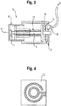
- Fig. 3 shows a schematic representation of the operating element in a second embodiment.
- Fig. 4 shows a schematic representation of a board with traces of a control element 6 of the invention.
- This board 14 is located on the rear housing wall 7 for contacting the rotation of the user on the retracting mechanism 9 rotationally acting movement to their electrical contact between the transmitter and receiver system 11 with the communication system 8 sure.
- the necessary two electrical phases are supplied via two separate lines of the transmitter and the receiver unit 11 via conductor tracks the sliding contacts 15, which contacts the board permanently with their tracks.
- This is a like in Fig. 4 shown interconnect image, consisting of a first conductor in the form of a circle with web and a second conductor, concentrically enclosing the circle of advantage.
- the subject of the invention is a cooking appliance with a previously described operating element.
- reception and reception strength is always understood as meaning transmission and its transmission strength.
- the transmitting / receiving unit 11 in an element which is not intended for value adjustment, but can be switched on and off only in the manner of a ballpoint pen.
Landscapes
- Engineering & Computer Science (AREA)
- General Physics & Mathematics (AREA)
- Physics & Mathematics (AREA)
- General Engineering & Computer Science (AREA)
- Mechanical Engineering (AREA)
- Computer Networks & Wireless Communication (AREA)
- Chemical & Material Sciences (AREA)
- Combustion & Propulsion (AREA)
- Automation & Control Theory (AREA)
- Food Science & Technology (AREA)
- Selective Calling Equipment (AREA)
- Cookers (AREA)
- Electric Ovens (AREA)
- Electric Stoves And Ranges (AREA)
- Induction Heating Cooking Devices (AREA)
Description
- Die folgende Erfindung betrifft ein Haushaltsgerät, insbesondere ein Gargerät.
- Aus dem Stand der Technik, beispielsweise der
EP1962167A1 , sind Bedienelemente bekannt, welche zur Werte- bzw. Parameterverstellung von Haushaltsgeräten geeignet sind. Dazu zählen u.a. Knebel am Gargerät zum Verstellen der Temperatur oder Betriebsart oder Knebel am Kochfeld zum Verstellen der Gasstufe. - Zudem sind aus dem Stand der Technik eine Reihe von Anwendungen für externe Datenquellen, beispielsweise Funkuhren, Onlinedatenbanken, Wartungsdienste usw. für Haushaltsgeräte bekannt, die ein Datenkommunikationssystem benötigen. Alternativ zu der Möglichkeit über eine kabelgebundene Datenkommunikationslösung an solche externen Anwendungen zu gelangen, bietet sich die kabellose Variante bei Haushaltsgeräten besonders an, da diese meist dezentral, variabel sowie unzugänglich im Haus angeordnet sind.
- Darüber hinaus ist aus der
EP2420735A1 eine Bedienvorrichtung für ein Hausgerät bekannt. Diese Bedienvorrichtung mit einem Bedienelement, welches auf einer Bedienfläche des mit der Bedienvorrichtung steuerbaren Hausgeräts mittels Magnetkraft haltbar ist und relativ zur Bedienfläche bewegbar und von dort abnehmbar positionierbar ist, und das Bedienelement eine integrierte und Energie drahtlos übertragende Energieversorgungseinrichtung aufweist, wobei in dem Bedienelement zumindest eine erste Spule der Energieversorgungseinrichtung angeordnet ist, welche in ein Ferritmaterial eingebettet ist. - Weiterer relevanter Stand der Technik ist in der
US2011/153871 A1 zu finden. - Bisherige kabellose Lösungen scheitern an der schlechten Empfangsqualität solch eines Datenkommunikationssystems, da das Haushaltsgerät aufgrund seiner Einbaulage zwischen anderen Gegenständen und seines metallischen Gehäuses gegen guten Empfang abgeschirmt ist.
- Die Aufgabe der vorliegenden Erfindung ist es deshalb, die drahtlosen Empfangs- und Sendeeigenschaften des Haushaltsgeräts zu externen Datenquellen zu verbessern.
- Erfindungsgemäß wird die Aufgabe jeweils durch die Gesamtheit der Merkmale der unabhängigen Ansprüche gelöst. Weitere vorteilhafte Ausgestaltungen der Erfindung sind in den Unteransprüchen beschrieben.
- Erfindungsgemäß ist ein Haushaltsgerät, insbesondere ein Gargerät, mit einem in eine Gerätefront versenkbar ausgebildeten Bedienelement, vorzugsweise ein Drehwähler zur Werte- und/oder Parameterverstellung des Haushaltsgeräts, mit einer Antenne zur Kommunikation mit einer externen Datenquelle ausgeführt. Da die Bedienelemente standardmäßig in den Raum, z. B. in die Küche weisen, ist demzufolge auch die Antenne dem Zentrum des Raumes zugewandt. Durch die konstruktive Ausgestaltung, dass das Bedienelement eine Antenne aufweist, wird eine verbesserte Empfangs-/Sendeeigenschaft des Haushaltsgeräts erzielt, da davon ausgegangen wird, dass im Zentrum des Raumes eine bessere Empfangsversorgung als im Randbereich des Raumes herrscht. Dabei ist das Bedienelement als Drehwähler zur Werte- und/oder Parameterverstellung des Haushaltsgeräts ausgebildet. Das Haushaltsgerät weist zumindest ein Sendersystem und/oder Empfangssystem auf. Dieses Kommunikationssystem dienen dem Haushaltsgerät zur drahtlosen Kopplung an ein Datenkommunikationssystem, wie z. B. dem WLAN und somit dem Internetzugang.
- Die Kappe des Bedienelements ist als Antenne ausgeführt. Dabei dient die Kappe des Bedienelements, welche vorzugsweise aus einem funkleitfähigen Material hergestellt ist, als Antenne des Sendersystems und/oder Empfangssystems. Durch diese Anordnung befindet sich die Antenne des Kommunikationssystems vor den abschirmenden Bauteilen der Gerätefront und erzielt einen besseren Empfang.
- Vorzugsweise ist das Bedienelement oder zumindest die Kappe ganz oder teilweise versenkbar in die Gerätefront ausgebildet. Durch diese Funktion ist die Kappe des Bedienelements mit der integrierten Antenne des Sende- und/oder Empfangssystems einer Kommunikationseinheit im Zustand der Benutzung des Haushaltsgeräts ausgefahren und somit vor der Gerätefront des Haushaltsgeräts, was zu einer verbesserten Empfangs- und Sendeleistung führt. Im versenkten Zustand des Bedienelements verschwindet die Kappe und somit die Antenne in der Front des Gargeräts, was zu einer ansehnlichen Optik des Haushaltsgeräts führt. Somit ist das Bedienelement in Richtung der Drehachse axial zwischen einer Betriebsstellung und einer Ruhestellung bewegbar. Diese versenkbare Betätigung des Bedienelements ist vorzugsweise auch zur Aktivierung bzw. Deaktivierung des Kommunikationssystems und/oder der Sende- und Empfangseinheit vorgesehen. Somit ist das Kommunikationssystem im eingefahrenen Zustand des Bedienelements in einem Aus- oder Standby-Betrieb und im ausgefahrenen Zustand des Bedienelements im Sende- und Empfangsbetrieb.
- Gemäß einer Variante weist das Bedienelement flexible Leiterbahnen auf. Diese flexiblen Leiterbahnen ermöglichen eine Signalübertragung über die Versenkmechanik hinweg von der Kappe zum Kommunikationssystem. Dies ist besonders wichtig, da die Versenkmechanik in Ausfahrrichtung und in Drehrichtung zur Werteverstellung flexibel ausgebildet sein muss.
- Gemäß einer Variante weist das Bedienelement eingespritzte Leiterbahnen auf. Bei dieser Variante übertragen die Einzelteile der Versenkmechanik mittels eingespritzter Leiterbahnen das Signal von der Kappe zum Kommunikationssystem sowie in die Gegenrichtung.
- Vorzugsweise weist das Bedienelement eine elektrische Platine mit Leiterplatten zur Kontaktierung auf. Die Kontaktierung der flexiblen oder eingespritzten Leiterbahnen zur Geräteelektronik, insbesondere zum Kommunikationssystem wird mittels einer Steckverbindung an der Schalteraufnahme realisiert. Um die notwendige elektronische Verbindung beim Drehen des Griffes zu ermöglichen, wird eine Platine mit Leiterbahnen und kontaktierenden Schleifkontakten eingesetzt.
- Vorzugsweise weist das Bedienelement ein Anzeigenelement auf. Das Anzeigenelement zeigt insbesondere den Empfang, den Versand oder die Empfangsqualität an. Das Anzeigenelement ist besonders nützlich, um den Benutzer des Haushaltsgeräts über den Status des Kommunikationssystems sowie den Sende- und Empfangseigenschaften des Haushaltsgeräts zu informieren.
- Die Erfindung löst die Aufgabe mit einem Haushaltsgerät, insbesondere einem Gargerät, aufweisend ein vorangegangenes Bedienelement. Die Sende-/Empfangseigenschaften des Kommunikationssystems des Haushaltsgeräts sind besonders gut, wenn zumindest ein Bauteil, insbesondere die in der Kappe integrierte Antenne, zumindest in einer Betriebsstellung vor der Gerätefront angeordnet ist.
- Weitere Vorteile und Einzelheiten der Erfindung werden anhand der in den schematischen Figuren dargestellten Ausführungsbeispielen näher erläutert. Dabei zeigt
- Fig. 1
- eine schematische perspektivische Darstellung eines Ausführungsbeispiels eines erfindungsgemäßen Haushaltsgerätes mit einem Ausführungsbeispiel eines erfindungsgemäßen Bedienelements;
- Fig. 2
- eine schematische Darstellung eines Bedienelements nach einem ersten Ausführungsbeispiel;
- Fig. 3
- eine schematische Darstellung eines Bedienelements nach einem zweiten Ausführungsbeispiel; und
- Fig. 4
- eine schematische Darstellung einer Platine mit Leiterbahnen.
- In den Figuren werden gleiche oder funktionsgleiche Elemente mit den gleichen Bezugszeichen versehen.
- Die folgenden Figuren zeigen das erfindungsgemäße Bedienelement für ein Hausgerät am Beispiel eines Gargeräts. Dadurch ist die Erfindung jedoch nicht auf den Einsatz in einem Gargerät beschränkt, sondern kann in allen Arten von Haushaltsgeräten, wie z. B. Kochfeldern, Waschmaschinen, Geschirrspülmaschinen, Trocknern, Kühlgeräten, usw. eingesetzt sein.
- In
Fig. 1 ist in einer perspektivischen Darstellung ein Gargerät 1 zum Zubereiten von Lebensmitteln gezeigt, welches im Ausführungsbeispiel ein Backofen ist. Das Gargerät 1 umfasst einen Garraum 2 zur Zubereitung von Lebensmitteln. Dieser Garraum 2 wird von einer gelenkig angeschlagenen Tür 3 verschlossen. Dabei bildet die Tür 3 einen wesentlichen Anteil an der Gerätefront 4, welche die dem Nutzer zugewandte Sichtfläche des Gargerätes bildet. Die Gerätefront 4 weist zudem einen Bedienabschnitt 5 auf, der den Nutzer die Eingabe von Systemparametern, wie z. B. Heizart oder Heiztemperatur dient. Diese Eingaben erfolgen in der Regel über Bedienelemente 6, wie z. B. Knebel, Drehknebel, Drucktasten, Mehrwegetasten, Touchbedienungen. Der Bedienabschnitt weist neben Bedienelementen 6 auch Ausgabeelemente, wie z. B. ein Display auf. -
Fig. 2 zeigt eine schematische Darstellung eines Bedienelements 6 in seiner geschnittenen Seitenansicht. Das hier als versenkbarer Drehknebel exemplarisch dargestelltes Bedienelement 6 eines Haushaltsgeräts dient zur Verstellung der Systemparameter. Dazu ist das Bedienelement 6 in den Bedienabschnitt 5 eingelassen, und bildet mit den anderen Systemkomponenten eine einheitliche, vorzugsweise ebene Gerätefront 4. Dazu ist das Gehäuse, auch als Schaltergriffaufnahme bezeichnet, flächenbündig zur Gerätefront 4 angebracht. Das Gehäuse 7 weist eine Versenkmechanik 9 auf, die eine Kappe 10 rotatorisch und versenkbar lagert. Die Kappe 10 dient dem Nutzer als greifbares Eingabeelement, welches der durch Drücken und Drehen zur Werteverstellung betätigt. Mittels der Versenkmechanik 9 ist die Kappe 10 derart gelagert, dass sie in einer ersten Position soweit vor der Gerätefront angeordnet ist, dass sie vom Nutzer gut greifbar und drehbar ist. Wird das Bedienelement 6 nicht benötigt, z. B. im ausgeschalteten Zustand des Gargeräts, in einem Standby-Betrieb oder soll das Bedienelement nicht für Kinder greifbar sein, wird die Kappe 10 in ihrer zweiten Position von der Versenkmechanik 9 derart im Gehäuse 7 aufgenommen, dass die Front der Kappe 10 bündig mit der Gerätefront 4 abschließt. Um dem Haushaltsgerät ein kabelloses Kommunikationssystem mit verbesserten Empfangseigenschaften bereitzustellen, weist das Bedienelement 6 zumindest ein Bauteil eines Kommunikationssystems 8 auf. Das Kommunikationssystem 8 besteht aus Hart- und Softwarekomponenten, die im Gargerät 1 angeordnet sind und vorzugsweise kabelgebunden, aber auch alternativ drahtlos mit dem Bedienelement 6 verbunden sind. Erfindungsgemäß weist die Kappe 10 des Bedienelements 6 einen Sender-/Empfänger 11 des Kommunikationssystems 8, der geeignet ist, Datenübertragungsformen, wie z. B. WLAN, Bluetooth, Infrarot oder ähnliche bekannte Systeme zu empfangen oder zu senden. Im nicht erfindungsgemäßen Ausführungsbeispiel ist die Sender-/Empfängereinheit 11 von vorne gesehen mittig unter der Kappe 10 angeordnet, wobei die Verbindung verbessert wird, wenn die Kappe eine Aussparung besitzt und/oder aus einem Material gefertigt ist, welches die Strahlen durch die Kappe zur Sender- und Empfängereinheit passieren lässt. Alternativ dazu ist die Sender-/Empfängereinheit 11 stirnseitig auf der Kappe oder an der Mantelfläche der Kappe oder als Wand um die Kappe angebracht. Die Erfindung sieht vor, die Kappe selbst aus einem leitfähigen Material zu gestalten, so dass die Kappe oder deren Beschichtung als Antenne dient. Gemäß dem Ausführungsbeispiel ausFig. 2 werden die empfangenen oder gesendeten Daten über flexible Leiterbahnen 12 an das Kommunikationssystem 8 weitergegeben. Zur Überbrückung der starr am Gargerät befestigten Gehäuseseite und der drehbar gelagerten Elemente der Bedienelemente 6 befindet sich gehäuseseitig eine Platine mit Leiterbahnen 14, die durch drehbar gelagerte Schleifkontakte 15 mit der elektrischen Spannung versorgt wird. Zur einfachen Montage des im Gargerät 1 befindlichen Kommunikationssystems 8 mit der Antennenfunktion des Bedienelements 6 befindet sich an der rückseitigen Gehäuseseite 7 ein Steckerelement 16. Um den Nutzer des Gargeräts 1 ein Feedback über die Funktion des Kommunikationssystems 8, insbesondere über die Qualität und/oder Quantität der Datenkommunikation und Sendeeigenschaften zu geben, ist am Bedienelement 6, insbesondere an der Kappe 10 oder in unmittelbarer Nähe dazu ein Anzeigeelement 17 vorgesehen. Dieses Anzeigeelement kann sowohl als zumindest eine LED-Anzeigenelement ausgeführt sein, als mehrfarbiges Anzeigenelement ausgeführt, als Siebensegmentanzeige oder als Volltextdisplay in Art eines Bildschirms ausgeführt sein. Dieses Anzeigenelement 17 kann sowohl stirnseitig auf der Kappe 10 des Bedienelements 6 angeordnet als auch umlaufend oder punktuell auf der Mantelfläche der Kappe 10 angeordnet sein. Alternativ ist dieses Anzeigeelement in unmittelbarer Nähe zum Bedienelement 6, insbesondere auf der Anzeigevorrichtung des Bedienabschnitts 5 angebracht. -
Fig. 3 zeigt eine schematische Darstellung des Bedienelements in einer zweiten Ausführungsform. Dabei erfolgt die Datenübertragung zwischen dem Kommunikationssystem 8 und der Sender-/Empfängereinheit 11 über in die Versenkmechanik 9 eingespritzte Leiterbahnen 13. Diese ermöglichen sowohl im ausgefahrenen Zustand des Bedienelements 6 sowie im eingefahrenen Zustand eine sichere Kontaktierung, da auf flexible Teile verzichtet werden kann. -
Fig. 4 zeigt eine schematische Darstellung einer Platine mit Leiterbahnen eines erfindungsgemäßen Bedienelements 6. Diese Platine 14 befindet sich auf der rückseitigen Gehäusewand 7 zur Kontaktierung der mittels der Drehbewegung des Nutzers auf die Versenkmechanik 9 rotatorisch wirkende Bewegung, um deren elektrische Kontaktierung zwischen Sender- und Empfängersystem 11 mit dem Kommunikationssystem 8 sicherzustellen. Die dazu notwendigen zwei elektrischen Phasen werden über zwei separate Leitungen von der Sender- und der Empfängereinheit 11 über Leiterbahnen den Schleifkontakten 15 zugeführt, welche die Platine mit ihren Leiterbahnen permanent kontaktiert. Dazu ist ein wie inFig. 4 gezeigtes Leiterbahnenbild, bestehend aus einer ersten Leiterbahn in Form eines Kreises mit Steg und einer zweiten Leiterbahn, die den Kreis konzentrisch umschließt von Vorteil. - Vorzugsweise ist der Gegenstand der Erfindung ein Gargerät mit einem vorangegangen beschriebenem Bedienelement.
- Im Sinne einer Datenkommunikationseinrichtung wird unter dem Begriff Empfang und Empfangsstärke immer auch das Senden und deren Sendestärke verstanden.
- Unabhängig von dem gezeigten Ausführungsbeispiel ist es auch möglich, die Sende-/Empfangseinheit 11 in einem Element auszuführen, das nicht zur Werteverstellung angedacht ist, sondern lediglich und in Art eines Kugelschreibers ein- und ausklickbar ist.
-
- 1
- Gargerät
- 2
- Garraum
- 3
- Tür
- 4
- Gerätefront
- 5
- Bedienabschnitt
- 6
- Bedienelement
- 7
- Gehäuse
- 8
- Kommunikationssystem
- 9
- Versenkmechanik
- 10
- Kappe
- 11
- Sender-/Empfänger
- 12
- flexible Leiterbahn
- 13
- eingespritzte Leiterbahn
- 14
- Platine mit Leiterbahnen
- 15
- Schleifkontakte
- 16
- Steckerelement
- 17
- Anzeigeelement
Claims (8)
- Haushaltsgerät, insbesondere Gargerät (1), mit einem in eine Gerätefront (4) versenkbar ausgebildeten Bedienelement, vorzugsweise ein Drehwähler zur Werte- und/oder Parameterverstellung des Haushaltsgeräts, wobei das Bedienelement (6) mit einer Antenne zur Kommunikation mit einer externen Datenquelle ausgeführt ist, dadurch gekennzeichnet, dass eine Kappe (10) des Bedienelements (6) als Antenne ausgeführt ist.
- Haushaltsgerät nach Anspruch 1, dadurch gekennzeichnet, dass zumindest die Kappe (10) des Bedienelements (6) in die Gerätefront (4) versenkbar ausgebildet ist.
- Haushaltsgerät nach einem der vorangegangenen Ansprüche, dadurch gekennzeichnet, dass das Bedienelement (6) flexible Leiterbahnen (12) aufweist.
- Haushaltsgerät nach Anspruch 1 oder 2, dadurch gekennzeichnet, dass das Bedienelement (6) eingespritzte Leiterbahnen (13) aufweist.
- Haushaltsgerät nach einem der vorangegangenen Ansprüche, dadurch gekennzeichnet, dass das Bedienelement (6) eine elektrische Platine mit Leiterbahnen (14) zur Kontaktierung aufweist.
- Haushaltsgerät nach einem der vorangegangenen Ansprüche, dadurch gekennzeichnet, dass das Bedienelement (6) ein Anzeigenelement (17) aufweist, dass zumindest den Empfang, den Versand oder die Empfangsqualität anzeigt.
- Haushaltsgerät nach einem der vorangegangenen Ansprüche, dadurch gekennzeichnet, dass das Haushaltsgerät ein Kommunikationssystem (8) und zumindest ein Bedienelement (6) aufweist.
- Haushaltsgerät nach Anspruch 7, dadurch gekennzeichnet, dass das Bedienelement (6) derart an der Gerätefront (4) angeordnet ist, dass zumindest ein Bauteil des Kommunikationssystems (8) zumindest in einer Betriebsstellung vor der Gerätefront (4) angeordnet ist.
Priority Applications (1)
| Application Number | Priority Date | Filing Date | Title |
|---|---|---|---|
| PL13783042T PL2920776T3 (pl) | 2012-11-13 | 2013-10-24 | Urządzenie gospodarstwa domowego z elementem sterującym |
Applications Claiming Priority (2)
| Application Number | Priority Date | Filing Date | Title |
|---|---|---|---|
| DE102012220615.9A DE102012220615A1 (de) | 2012-11-13 | 2012-11-13 | Bedienelement für ein Haushaltsgerät |
| PCT/EP2013/072271 WO2014075886A2 (de) | 2012-11-13 | 2013-10-24 | Bedienelement für ein haushaltsgerät |
Publications (2)
| Publication Number | Publication Date |
|---|---|
| EP2920776A2 EP2920776A2 (de) | 2015-09-23 |
| EP2920776B1 true EP2920776B1 (de) | 2017-03-01 |
Family
ID=49486480
Family Applications (1)
| Application Number | Title | Priority Date | Filing Date |
|---|---|---|---|
| EP13783042.8A Active EP2920776B1 (de) | 2012-11-13 | 2013-10-24 | Haushaltsgerät mit bedienelement |
Country Status (6)
| Country | Link |
|---|---|
| US (1) | US9907434B2 (de) |
| EP (1) | EP2920776B1 (de) |
| DE (1) | DE102012220615A1 (de) |
| ES (1) | ES2621354T3 (de) |
| PL (1) | PL2920776T3 (de) |
| WO (1) | WO2014075886A2 (de) |
Cited By (1)
| Publication number | Priority date | Publication date | Assignee | Title |
|---|---|---|---|---|
| DE102016218493A1 (de) | 2016-09-27 | 2018-03-29 | BSH Hausgeräte GmbH | Thermostatanordnung und Haushaltsgargerät |
Families Citing this family (1)
| Publication number | Priority date | Publication date | Assignee | Title |
|---|---|---|---|---|
| DE102015215987A1 (de) * | 2015-08-21 | 2017-02-23 | BSH Hausgeräte GmbH | Dualband Antenne |
Family Cites Families (48)
| Publication number | Priority date | Publication date | Assignee | Title |
|---|---|---|---|---|
| US5276454A (en) * | 1991-06-17 | 1994-01-04 | Motorola, Inc. | Control and antenna mount assembly |
| CA2117561C (en) * | 1993-01-29 | 1998-04-28 | Paul John Moller | Antenna assembly for radio circuit and method therefor |
| JP2574256Y2 (ja) * | 1993-02-19 | 1998-06-11 | 松下電器産業株式会社 | アンテナ装置 |
| US5903832A (en) * | 1995-12-21 | 1999-05-11 | Nokia Mobile Phones Llimited | Mobile terminal having enhanced system selection capability |
| US5684672A (en) * | 1996-02-20 | 1997-11-04 | International Business Machines Corporation | Laptop computer with an integrated multi-mode antenna |
| US6173316B1 (en) * | 1998-04-08 | 2001-01-09 | Geoworks Corporation | Wireless communication device with markup language based man-machine interface |
| JP2003179420A (ja) * | 1998-10-29 | 2003-06-27 | Koji Sasano | アンテナ |
| DE19903223B4 (de) * | 1999-01-27 | 2007-01-04 | BSH Bosch und Siemens Hausgeräte GmbH | Bedieneinheit mit versenkbarem Bedienknopf |
| US6507762B1 (en) * | 1999-03-31 | 2003-01-14 | International Business Machines Corporation | Method and system for remotely controlling an appliance using a personal digital assistant |
| DE19928229A1 (de) * | 1999-06-19 | 2000-12-21 | Mannesmann Vdo Ag | Versenkbarer Drehknopf |
| JP2001053517A (ja) * | 1999-08-06 | 2001-02-23 | Sony Corp | アンテナ装置及び携帯無線機 |
| JP2001053518A (ja) * | 1999-08-06 | 2001-02-23 | Sony Corp | アンテナ装置及び携帯無線機 |
| US6691233B1 (en) * | 1999-11-18 | 2004-02-10 | Ecrio Inc. | Battery operated ink capture device that operates in a normal power mode during active use and a minimum power mode during absence of active use |
| DE19959224B4 (de) | 1999-12-08 | 2010-07-01 | E.G.O. Elektro-Gerätebau GmbH | System bestehend aus einem Elektrokochgerät und einer davon gesonderten Bedieneinheit |
| DE19959715A1 (de) * | 1999-12-10 | 2001-06-13 | Thomson Brandt Gmbh | Gerät zum drahtlosen Empfang von Funksignalen |
| US6546263B1 (en) * | 2000-06-12 | 2003-04-08 | Ericsson Inc. | Apparatus and method for compact icon display |
| US20020094778A1 (en) * | 2001-01-18 | 2002-07-18 | Cannon Joseph M. | Bluetooth connection quality indicator |
| DE10151937A1 (de) * | 2001-10-22 | 2003-04-30 | Bsh Bosch Siemens Hausgeraete | Gargerät mit einer Schnellaufheizeinheit |
| US7102640B1 (en) * | 2002-03-21 | 2006-09-05 | Nokia Corporation | Service/device indication with graphical interface |
| ITTO20030315A1 (it) * | 2003-04-23 | 2004-10-24 | Itw Ind Components Srl | Manopola di comando del tipo a scomparsa ad estrazione |
| GB2422692B (en) | 2005-01-31 | 2009-08-12 | Hewlett Packard Development Co | Software updates for electronic appliances |
| DE102005028095A1 (de) * | 2005-06-17 | 2007-01-04 | Abb Patent Gmbh | Sicherheitssystem für ein wärmeproduzierendes Gerät, insbesondere für einen elektrischen Herd |
| JP4404057B2 (ja) * | 2006-02-10 | 2010-01-27 | ソニー株式会社 | 無接点スイッチとそれを用いた記録メディアおよび操作部材 |
| DE102006030550A1 (de) * | 2006-07-03 | 2008-01-17 | BSH Bosch und Siemens Hausgeräte GmbH | Bedieneinheit zur Anzeige und/oder Einstellung von Betriebsparameterwerten von zumindest einem Hausgerät |
| DE102007008897A1 (de) * | 2007-02-23 | 2008-08-28 | BSH Bosch und Siemens Hausgeräte GmbH | Versenkbares Bedienelement für ein Hausgerät und Hausgerät, insbesondere Backofen |
| DE102008027471A1 (de) * | 2008-06-09 | 2009-12-10 | BSH Bosch und Siemens Hausgeräte GmbH | Knebel für ein Haushaltsgerät |
| DE102009006434B3 (de) * | 2009-01-22 | 2010-06-17 | E.G.O. Elektro-Gerätebau GmbH | Bedieneinrichtung für ein Elektrogerät und Bedienblende |
| US8700809B2 (en) | 2009-12-21 | 2014-04-15 | Whirlpool Corporation | Substance communicating device with activatable connector and cycle structure |
| IT1398224B1 (it) | 2010-02-25 | 2013-02-22 | Niro Plan Ag Ora Franke Technology And Trademark Ltd | Sistema di controllo di un elettrodomestico. |
| DE102010039560A1 (de) * | 2010-08-20 | 2012-02-23 | BSH Bosch und Siemens Hausgeräte GmbH | Bedienvorrichtung für ein Hausgerät mit einer Energieversorgungseinrichtung sowie Hausgerät zum Zubereiten von Lebensmitteln mit einer derartigen Bedienvorrichtung |
| DE102010039558A1 (de) | 2010-08-20 | 2012-02-23 | BSH Bosch und Siemens Hausgeräte GmbH | Bedienvorrichtung für ein Hausgerät mit einer Energieversorgungseinrichtung sowie Hausgerät zum Zubereiten von Lebensmitteln mit einer derartigen Bedienvorrichtung |
| US10007290B2 (en) * | 2010-09-15 | 2018-06-26 | Inventus Engineering Gmbh | Haptic operating device with a rotating element and method |
| DE102010048081A1 (de) * | 2010-10-06 | 2012-04-12 | E.G.O. Elektro-Gerätebau GmbH | Bedieneinrichtung und Bedienverfahren |
| DE102010062578A1 (de) * | 2010-12-08 | 2012-06-14 | BSH Bosch und Siemens Hausgeräte GmbH | Bedienvorrichtung für ein Haushaltsgerät sowie Kochfeld mit einer derartigen Bedienvorrichtung |
| SI23686A (sl) | 2011-03-03 | 2012-09-28 | Albin Smrke | Univerzalna naprava za regulacijo energije v obliki gumba |
| US20120329524A1 (en) * | 2011-06-22 | 2012-12-27 | Kent Joel C | Touch sensor and antenna integration along an electronic device housing |
| JP2013098764A (ja) * | 2011-11-01 | 2013-05-20 | Sony Corp | 電子機器 |
| US9331391B2 (en) * | 2012-02-14 | 2016-05-03 | Htc Corporation | Mobile device |
| US8630741B1 (en) * | 2012-09-30 | 2014-01-14 | Nest Labs, Inc. | Automated presence detection and presence-related control within an intelligent controller |
| US9065170B2 (en) * | 2012-10-04 | 2015-06-23 | Harris Corporation | Communication device comprising an external control with an embedded antenna assembly |
| EP2932176B1 (de) * | 2012-12-14 | 2019-07-10 | Arçelik Anonim Sirketi | Ein kältegerät aufweisend einen drehknopf für die einstellung der kühlkammertemperatur |
| JP5646018B1 (ja) * | 2013-08-07 | 2014-12-24 | 三菱電機株式会社 | 設置場所策定支援方法、端末装置、設置場所策定支援システム及びプログラム |
| US9160392B2 (en) * | 2014-01-23 | 2015-10-13 | Harris Corporation | Rotary knob with integrated antenna |
| CN205433271U (zh) * | 2014-08-19 | 2016-08-10 | 美亚知识产权有限公司 | 食物制备系统、控制旋钮、套件和烹饪装置 |
| US9673511B2 (en) * | 2014-09-22 | 2017-06-06 | Intel Corporation | Exciting dual frequency bands from an antenna component with a dual branch coupling feed |
| KR102245184B1 (ko) * | 2014-11-21 | 2021-04-27 | 삼성전자주식회사 | 안테나를 갖는 전자 장치 |
| US20160322695A1 (en) * | 2015-04-30 | 2016-11-03 | Motorola Solutions, Inc | Rotary control with integrated antenna |
| US9644847B2 (en) * | 2015-05-05 | 2017-05-09 | June Life, Inc. | Connected food preparation system and method of use |
-
2012
- 2012-11-13 DE DE102012220615.9A patent/DE102012220615A1/de not_active Withdrawn
-
2013
- 2013-10-24 EP EP13783042.8A patent/EP2920776B1/de active Active
- 2013-10-24 WO PCT/EP2013/072271 patent/WO2014075886A2/de not_active Ceased
- 2013-10-24 ES ES13783042.8T patent/ES2621354T3/es active Active
- 2013-10-24 PL PL13783042T patent/PL2920776T3/pl unknown
- 2013-10-24 US US14/439,699 patent/US9907434B2/en not_active Expired - Fee Related
Cited By (1)
| Publication number | Priority date | Publication date | Assignee | Title |
|---|---|---|---|---|
| DE102016218493A1 (de) | 2016-09-27 | 2018-03-29 | BSH Hausgeräte GmbH | Thermostatanordnung und Haushaltsgargerät |
Also Published As
| Publication number | Publication date |
|---|---|
| ES2621354T3 (es) | 2017-07-03 |
| US20150282666A1 (en) | 2015-10-08 |
| US9907434B2 (en) | 2018-03-06 |
| WO2014075886A2 (de) | 2014-05-22 |
| DE102012220615A1 (de) | 2014-05-15 |
| WO2014075886A3 (de) | 2015-04-16 |
| EP2920776A2 (de) | 2015-09-23 |
| PL2920776T3 (pl) | 2017-07-31 |
Similar Documents
| Publication | Publication Date | Title |
|---|---|---|
| EP2739910B1 (de) | Haushaltsgerät mit antenne | |
| EP2430367B1 (de) | Portable, insbesondere medienfähige konsole, und gargerät | |
| DE102013021093B4 (de) | Bedienvorrichtung | |
| WO2010124966A1 (de) | Verfahren zum betreiben eines haushaltsgeräts, portable bedieneinheit und haushaltsgerät | |
| DE102012211898A1 (de) | Türschließvorrichtung | |
| EP2570051A1 (de) | Möbelanordnung | |
| EP2920776B1 (de) | Haushaltsgerät mit bedienelement | |
| DE102014215705A1 (de) | Kochgerät mit Nahfeldantennen | |
| EP2487663A1 (de) | Fernsteuerung | |
| EP1449300A2 (de) | Elektrisches haushaltsgerät | |
| DE102004005111B4 (de) | Hausgerätebedienvorrichtung | |
| DE102015003337B4 (de) | Anzeige- und/oder Bedienvorrichtung für ein elektronisches Haushaltsgerät | |
| DE102011004295B4 (de) | Fernbetätigungseinrichtung für ein Bodenreinigungsgerät, Bodenreinigungsgerät und Verfahren zum Betrieb eines Bodenreinigungsgeräts | |
| EP2662629A1 (de) | Hausgerät | |
| WO2016008723A1 (de) | Elektronische benutzerschnittstelle mit einer abschirmvorrichtung | |
| DE19961457A1 (de) | Kochfeld mit beweglichem Bedienfeld | |
| DE102005063070A1 (de) | Vorrichtung zum Steuern eines Betriebsparameters eines elektrischen Geräts | |
| EP0177811B1 (de) | Steuerschalter | |
| DE102010027799A1 (de) | Bedienvorrichtung für ein Hausgerät sowie Hausgerät mit einer Bedienvorrichtung | |
| DE102006030549A1 (de) | Halterung für ein Elektronikmodul | |
| DE102013216361B4 (de) | Handfernbedienung zur Steuerung von elektrischen Verbrauchern | |
| DE202022100334U1 (de) | Bedienvorrichtung | |
| DE102004020977B4 (de) | Vorrichtung zur variablen Einstellung der Leistung einer Heizeinrichtung mit mindestens zwei Heizkreisen | |
| EP2860828A1 (de) | Zwischenstecker | |
| DE102024112348A1 (de) | Betätigungsbaugruppe und Küchengerät |
Legal Events
| Date | Code | Title | Description |
|---|---|---|---|
| PUAI | Public reference made under article 153(3) epc to a published international application that has entered the european phase |
Free format text: ORIGINAL CODE: 0009012 |
|
| AK | Designated contracting states |
Kind code of ref document: A2 Designated state(s): AL AT BE BG CH CY CZ DE DK EE ES FI FR GB GR HR HU IE IS IT LI LT LU LV MC MK MT NL NO PL PT RO RS SE SI SK SM TR |
|
| AX | Request for extension of the european patent |
Extension state: BA ME |
|
| 17P | Request for examination filed |
Effective date: 20151016 |
|
| RBV | Designated contracting states (corrected) |
Designated state(s): AL AT BE BG CH CY CZ DE DK EE ES FI FR GB GR HR HU IE IS IT LI LT LU LV MC MK MT NL NO PL PT RO RS SE SI SK SM TR |
|
| DAX | Request for extension of the european patent (deleted) | ||
| REG | Reference to a national code |
Ref country code: DE Ref legal event code: R079 Ref document number: 502013006549 Country of ref document: DE Free format text: PREVIOUS MAIN CLASS: G08C0023040000 Ipc: G05B0015020000 |
|
| GRAP | Despatch of communication of intention to grant a patent |
Free format text: ORIGINAL CODE: EPIDOSNIGR1 |
|
| RIC1 | Information provided on ipc code assigned before grant |
Ipc: F24C 7/08 20060101ALI20160905BHEP Ipc: G08C 23/04 20060101ALI20160905BHEP Ipc: G05B 15/02 20060101AFI20160905BHEP Ipc: A47J 36/00 20060101ALI20160905BHEP Ipc: G08C 17/02 20060101ALI20160905BHEP |
|
| INTG | Intention to grant announced |
Effective date: 20161005 |
|
| GRAS | Grant fee paid |
Free format text: ORIGINAL CODE: EPIDOSNIGR3 |
|
| GRAA | (expected) grant |
Free format text: ORIGINAL CODE: 0009210 |
|
| AK | Designated contracting states |
Kind code of ref document: B1 Designated state(s): AL AT BE BG CH CY CZ DE DK EE ES FI FR GB GR HR HU IE IS IT LI LT LU LV MC MK MT NL NO PL PT RO RS SE SI SK SM TR |
|
| REG | Reference to a national code |
Ref country code: GB Ref legal event code: FG4D Free format text: NOT ENGLISH |
|
| REG | Reference to a national code |
Ref country code: CH Ref legal event code: EP Ref country code: AT Ref legal event code: REF Ref document number: 872055 Country of ref document: AT Kind code of ref document: T Effective date: 20170315 |
|
| REG | Reference to a national code |
Ref country code: IE Ref legal event code: FG4D Free format text: LANGUAGE OF EP DOCUMENT: GERMAN |
|
| REG | Reference to a national code |
Ref country code: DE Ref legal event code: R096 Ref document number: 502013006549 Country of ref document: DE |
|
| REG | Reference to a national code |
Ref country code: ES Ref legal event code: FG2A Ref document number: 2621354 Country of ref document: ES Kind code of ref document: T3 Effective date: 20170703 |
|
| REG | Reference to a national code |
Ref country code: NL Ref legal event code: MP Effective date: 20170301 |
|
| REG | Reference to a national code |
Ref country code: LT Ref legal event code: MG4D |
|
| PG25 | Lapsed in a contracting state [announced via postgrant information from national office to epo] |
Ref country code: HR Free format text: LAPSE BECAUSE OF FAILURE TO SUBMIT A TRANSLATION OF THE DESCRIPTION OR TO PAY THE FEE WITHIN THE PRESCRIBED TIME-LIMIT Effective date: 20170301 Ref country code: LT Free format text: LAPSE BECAUSE OF FAILURE TO SUBMIT A TRANSLATION OF THE DESCRIPTION OR TO PAY THE FEE WITHIN THE PRESCRIBED TIME-LIMIT Effective date: 20170301 Ref country code: FI Free format text: LAPSE BECAUSE OF FAILURE TO SUBMIT A TRANSLATION OF THE DESCRIPTION OR TO PAY THE FEE WITHIN THE PRESCRIBED TIME-LIMIT Effective date: 20170301 Ref country code: GR Free format text: LAPSE BECAUSE OF FAILURE TO SUBMIT A TRANSLATION OF THE DESCRIPTION OR TO PAY THE FEE WITHIN THE PRESCRIBED TIME-LIMIT Effective date: 20170602 Ref country code: NO Free format text: LAPSE BECAUSE OF FAILURE TO SUBMIT A TRANSLATION OF THE DESCRIPTION OR TO PAY THE FEE WITHIN THE PRESCRIBED TIME-LIMIT Effective date: 20170601 |
|
| PG25 | Lapsed in a contracting state [announced via postgrant information from national office to epo] |
Ref country code: SE Free format text: LAPSE BECAUSE OF FAILURE TO SUBMIT A TRANSLATION OF THE DESCRIPTION OR TO PAY THE FEE WITHIN THE PRESCRIBED TIME-LIMIT Effective date: 20170301 Ref country code: RS Free format text: LAPSE BECAUSE OF FAILURE TO SUBMIT A TRANSLATION OF THE DESCRIPTION OR TO PAY THE FEE WITHIN THE PRESCRIBED TIME-LIMIT Effective date: 20170301 Ref country code: LV Free format text: LAPSE BECAUSE OF FAILURE TO SUBMIT A TRANSLATION OF THE DESCRIPTION OR TO PAY THE FEE WITHIN THE PRESCRIBED TIME-LIMIT Effective date: 20170301 Ref country code: BG Free format text: LAPSE BECAUSE OF FAILURE TO SUBMIT A TRANSLATION OF THE DESCRIPTION OR TO PAY THE FEE WITHIN THE PRESCRIBED TIME-LIMIT Effective date: 20170601 |
|
| PG25 | Lapsed in a contracting state [announced via postgrant information from national office to epo] |
Ref country code: NL Free format text: LAPSE BECAUSE OF FAILURE TO SUBMIT A TRANSLATION OF THE DESCRIPTION OR TO PAY THE FEE WITHIN THE PRESCRIBED TIME-LIMIT Effective date: 20170301 |
|
| REG | Reference to a national code |
Ref country code: FR Ref legal event code: PLFP Year of fee payment: 5 |
|
| PG25 | Lapsed in a contracting state [announced via postgrant information from national office to epo] |
Ref country code: EE Free format text: LAPSE BECAUSE OF FAILURE TO SUBMIT A TRANSLATION OF THE DESCRIPTION OR TO PAY THE FEE WITHIN THE PRESCRIBED TIME-LIMIT Effective date: 20170301 Ref country code: RO Free format text: LAPSE BECAUSE OF FAILURE TO SUBMIT A TRANSLATION OF THE DESCRIPTION OR TO PAY THE FEE WITHIN THE PRESCRIBED TIME-LIMIT Effective date: 20170301 Ref country code: SK Free format text: LAPSE BECAUSE OF FAILURE TO SUBMIT A TRANSLATION OF THE DESCRIPTION OR TO PAY THE FEE WITHIN THE PRESCRIBED TIME-LIMIT Effective date: 20170301 Ref country code: CZ Free format text: LAPSE BECAUSE OF FAILURE TO SUBMIT A TRANSLATION OF THE DESCRIPTION OR TO PAY THE FEE WITHIN THE PRESCRIBED TIME-LIMIT Effective date: 20170301 |
|
| PG25 | Lapsed in a contracting state [announced via postgrant information from national office to epo] |
Ref country code: SM Free format text: LAPSE BECAUSE OF FAILURE TO SUBMIT A TRANSLATION OF THE DESCRIPTION OR TO PAY THE FEE WITHIN THE PRESCRIBED TIME-LIMIT Effective date: 20170301 Ref country code: IS Free format text: LAPSE BECAUSE OF FAILURE TO SUBMIT A TRANSLATION OF THE DESCRIPTION OR TO PAY THE FEE WITHIN THE PRESCRIBED TIME-LIMIT Effective date: 20170701 Ref country code: PT Free format text: LAPSE BECAUSE OF FAILURE TO SUBMIT A TRANSLATION OF THE DESCRIPTION OR TO PAY THE FEE WITHIN THE PRESCRIBED TIME-LIMIT Effective date: 20170703 |
|
| REG | Reference to a national code |
Ref country code: DE Ref legal event code: R097 Ref document number: 502013006549 Country of ref document: DE |
|
| PLBE | No opposition filed within time limit |
Free format text: ORIGINAL CODE: 0009261 |
|
| STAA | Information on the status of an ep patent application or granted ep patent |
Free format text: STATUS: NO OPPOSITION FILED WITHIN TIME LIMIT |
|
| PG25 | Lapsed in a contracting state [announced via postgrant information from national office to epo] |
Ref country code: DK Free format text: LAPSE BECAUSE OF FAILURE TO SUBMIT A TRANSLATION OF THE DESCRIPTION OR TO PAY THE FEE WITHIN THE PRESCRIBED TIME-LIMIT Effective date: 20170301 |
|
| 26N | No opposition filed |
Effective date: 20171204 |
|
| PG25 | Lapsed in a contracting state [announced via postgrant information from national office to epo] |
Ref country code: SI Free format text: LAPSE BECAUSE OF FAILURE TO SUBMIT A TRANSLATION OF THE DESCRIPTION OR TO PAY THE FEE WITHIN THE PRESCRIBED TIME-LIMIT Effective date: 20170301 |
|
| PG25 | Lapsed in a contracting state [announced via postgrant information from national office to epo] |
Ref country code: MC Free format text: LAPSE BECAUSE OF FAILURE TO SUBMIT A TRANSLATION OF THE DESCRIPTION OR TO PAY THE FEE WITHIN THE PRESCRIBED TIME-LIMIT Effective date: 20170301 |
|
| REG | Reference to a national code |
Ref country code: CH Ref legal event code: PL |
|
| REG | Reference to a national code |
Ref country code: IE Ref legal event code: MM4A |
|
| PG25 | Lapsed in a contracting state [announced via postgrant information from national office to epo] |
Ref country code: CH Free format text: LAPSE BECAUSE OF NON-PAYMENT OF DUE FEES Effective date: 20171031 Ref country code: LI Free format text: LAPSE BECAUSE OF NON-PAYMENT OF DUE FEES Effective date: 20171031 Ref country code: LU Free format text: LAPSE BECAUSE OF NON-PAYMENT OF DUE FEES Effective date: 20171024 |
|
| REG | Reference to a national code |
Ref country code: BE Ref legal event code: MM Effective date: 20171031 |
|
| PG25 | Lapsed in a contracting state [announced via postgrant information from national office to epo] |
Ref country code: BE Free format text: LAPSE BECAUSE OF NON-PAYMENT OF DUE FEES Effective date: 20171031 |
|
| PG25 | Lapsed in a contracting state [announced via postgrant information from national office to epo] |
Ref country code: MT Free format text: LAPSE BECAUSE OF FAILURE TO SUBMIT A TRANSLATION OF THE DESCRIPTION OR TO PAY THE FEE WITHIN THE PRESCRIBED TIME-LIMIT Effective date: 20170301 |
|
| REG | Reference to a national code |
Ref country code: FR Ref legal event code: PLFP Year of fee payment: 6 |
|
| PG25 | Lapsed in a contracting state [announced via postgrant information from national office to epo] |
Ref country code: IE Free format text: LAPSE BECAUSE OF NON-PAYMENT OF DUE FEES Effective date: 20171024 |
|
| PG25 | Lapsed in a contracting state [announced via postgrant information from national office to epo] |
Ref country code: HU Free format text: LAPSE BECAUSE OF FAILURE TO SUBMIT A TRANSLATION OF THE DESCRIPTION OR TO PAY THE FEE WITHIN THE PRESCRIBED TIME-LIMIT; INVALID AB INITIO Effective date: 20131024 |
|
| PG25 | Lapsed in a contracting state [announced via postgrant information from national office to epo] |
Ref country code: CY Free format text: LAPSE BECAUSE OF FAILURE TO SUBMIT A TRANSLATION OF THE DESCRIPTION OR TO PAY THE FEE WITHIN THE PRESCRIBED TIME-LIMIT Effective date: 20170301 |
|
| PG25 | Lapsed in a contracting state [announced via postgrant information from national office to epo] |
Ref country code: MK Free format text: LAPSE BECAUSE OF FAILURE TO SUBMIT A TRANSLATION OF THE DESCRIPTION OR TO PAY THE FEE WITHIN THE PRESCRIBED TIME-LIMIT Effective date: 20170301 |
|
| REG | Reference to a national code |
Ref country code: AT Ref legal event code: MM01 Ref document number: 872055 Country of ref document: AT Kind code of ref document: T Effective date: 20181024 |
|
| PG25 | Lapsed in a contracting state [announced via postgrant information from national office to epo] |
Ref country code: AT Free format text: LAPSE BECAUSE OF NON-PAYMENT OF DUE FEES Effective date: 20181024 |
|
| PG25 | Lapsed in a contracting state [announced via postgrant information from national office to epo] |
Ref country code: AL Free format text: LAPSE BECAUSE OF FAILURE TO SUBMIT A TRANSLATION OF THE DESCRIPTION OR TO PAY THE FEE WITHIN THE PRESCRIBED TIME-LIMIT Effective date: 20170301 |
|
| REG | Reference to a national code |
Ref country code: DE Ref legal event code: R084 Ref document number: 502013006549 Country of ref document: DE |
|
| REG | Reference to a national code |
Ref country code: ES Ref legal event code: GC2A Effective date: 20240904 |
|
| PGFP | Annual fee paid to national office [announced via postgrant information from national office to epo] |
Ref country code: DE Payment date: 20241031 Year of fee payment: 12 |
|
| PGFP | Annual fee paid to national office [announced via postgrant information from national office to epo] |
Ref country code: PL Payment date: 20241011 Year of fee payment: 12 |
|
| PGFP | Annual fee paid to national office [announced via postgrant information from national office to epo] |
Ref country code: GB Payment date: 20241024 Year of fee payment: 12 |
|
| PGFP | Annual fee paid to national office [announced via postgrant information from national office to epo] |
Ref country code: FR Payment date: 20241025 Year of fee payment: 12 |
|
| PGFP | Annual fee paid to national office [announced via postgrant information from national office to epo] |
Ref country code: IT Payment date: 20241031 Year of fee payment: 12 Ref country code: ES Payment date: 20241118 Year of fee payment: 12 |
|
| PGFP | Annual fee paid to national office [announced via postgrant information from national office to epo] |
Ref country code: TR Payment date: 20241016 Year of fee payment: 12 |