EP2920826B1 - Anordnung zur umwandlung von mechanischer arbeit in elektrische energie und zählvorrichtung damit - Google Patents
Anordnung zur umwandlung von mechanischer arbeit in elektrische energie und zählvorrichtung damit Download PDFInfo
- Publication number
- EP2920826B1 EP2920826B1 EP13803192.7A EP13803192A EP2920826B1 EP 2920826 B1 EP2920826 B1 EP 2920826B1 EP 13803192 A EP13803192 A EP 13803192A EP 2920826 B1 EP2920826 B1 EP 2920826B1
- Authority
- EP
- European Patent Office
- Prior art keywords
- counting device
- support
- assembly
- bending transducer
- strip
- Prior art date
- Legal status (The legal status is an assumption and is not a legal conclusion. Google has not performed a legal analysis and makes no representation as to the accuracy of the status listed.)
- Not-in-force
Links
Images
Classifications
-
- H—ELECTRICITY
- H02—GENERATION; CONVERSION OR DISTRIBUTION OF ELECTRIC POWER
- H02N—ELECTRIC MACHINES NOT OTHERWISE PROVIDED FOR
- H02N2/00—Electric machines in general using piezoelectric effect, electrostriction or magnetostriction
- H02N2/18—Electric machines in general using piezoelectric effect, electrostriction or magnetostriction producing electrical output from mechanical input, e.g. generators
-
- F—MECHANICAL ENGINEERING; LIGHTING; HEATING; WEAPONS; BLASTING
- F21—LIGHTING
- F21S—NON-PORTABLE LIGHTING DEVICES; SYSTEMS THEREOF; VEHICLE LIGHTING DEVICES SPECIALLY ADAPTED FOR VEHICLE EXTERIORS
- F21S8/00—Lighting devices intended for fixed installation
- F21S8/03—Lighting devices intended for fixed installation of surface-mounted type
- F21S8/033—Lighting devices intended for fixed installation of surface-mounted type the surface being a wall or like vertical structure, e.g. building facade
-
- F—MECHANICAL ENGINEERING; LIGHTING; HEATING; WEAPONS; BLASTING
- F21—LIGHTING
- F21S—NON-PORTABLE LIGHTING DEVICES; SYSTEMS THEREOF; VEHICLE LIGHTING DEVICES SPECIALLY ADAPTED FOR VEHICLE EXTERIORS
- F21S8/00—Lighting devices intended for fixed installation
- F21S8/04—Lighting devices intended for fixed installation intended only for mounting on a ceiling or the like overhead structures
- F21S8/06—Lighting devices intended for fixed installation intended only for mounting on a ceiling or the like overhead structures by suspension
-
- F—MECHANICAL ENGINEERING; LIGHTING; HEATING; WEAPONS; BLASTING
- F21—LIGHTING
- F21V—FUNCTIONAL FEATURES OR DETAILS OF LIGHTING DEVICES OR SYSTEMS THEREOF; STRUCTURAL COMBINATIONS OF LIGHTING DEVICES WITH OTHER ARTICLES, NOT OTHERWISE PROVIDED FOR
- F21V7/00—Reflectors for light sources
- F21V7/0008—Reflectors for light sources providing for indirect lighting
- F21V7/0016—Reflectors for light sources providing for indirect lighting on lighting devices that also provide for direct lighting, e.g. by means of independent light sources, by splitting of the light beam, by switching between both lighting modes
-
- G—PHYSICS
- G06—COMPUTING OR CALCULATING; COUNTING
- G06M—COUNTING MECHANISMS; COUNTING OF OBJECTS NOT OTHERWISE PROVIDED FOR
- G06M1/00—Design features of general application
- G06M1/08—Design features of general application for actuating the drive
- G06M1/10—Design features of general application for actuating the drive by electric or magnetic means
- G06M1/108—Design features of general application for actuating the drive by electric or magnetic means by electronic means
-
- H—ELECTRICITY
- H03—ELECTRONIC CIRCUITRY
- H03K—PULSE TECHNIQUE
- H03K21/00—Details of pulse counters or frequency dividers
- H03K21/02—Input circuits
- H03K21/026—Input circuits comprising logic circuits
-
- H—ELECTRICITY
- H03—ELECTRONIC CIRCUITRY
- H03K—PULSE TECHNIQUE
- H03K21/00—Details of pulse counters or frequency dividers
- H03K21/18—Circuits for visual indication of the result
-
- H—ELECTRICITY
- H03—ELECTRONIC CIRCUITRY
- H03K—PULSE TECHNIQUE
- H03K21/00—Details of pulse counters or frequency dividers
- H03K21/40—Monitoring; Error detection; Preventing or correcting improper counter operation
- H03K21/406—Synchronisation of counters
-
- H—ELECTRICITY
- H10—SEMICONDUCTOR DEVICES; ELECTRIC SOLID-STATE DEVICES NOT OTHERWISE PROVIDED FOR
- H10N—ELECTRIC SOLID-STATE DEVICES NOT OTHERWISE PROVIDED FOR
- H10N30/00—Piezoelectric or electrostrictive devices
- H10N30/30—Piezoelectric or electrostrictive devices with mechanical input and electrical output, e.g. functioning as generators or sensors
- H10N30/304—Beam type
-
- F—MECHANICAL ENGINEERING; LIGHTING; HEATING; WEAPONS; BLASTING
- F21—LIGHTING
- F21V—FUNCTIONAL FEATURES OR DETAILS OF LIGHTING DEVICES OR SYSTEMS THEREOF; STRUCTURAL COMBINATIONS OF LIGHTING DEVICES WITH OTHER ARTICLES, NOT OTHERWISE PROVIDED FOR
- F21V2200/00—Use of light guides, e.g. fibre optic devices, in lighting devices or systems
- F21V2200/20—Use of light guides, e.g. fibre optic devices, in lighting devices or systems of light guides of a generally planar shape
-
- F—MECHANICAL ENGINEERING; LIGHTING; HEATING; WEAPONS; BLASTING
- F21—LIGHTING
- F21Y—INDEXING SCHEME ASSOCIATED WITH SUBCLASSES F21K, F21L, F21S and F21V, RELATING TO THE FORM OR THE KIND OF THE LIGHT SOURCES OR OF THE COLOUR OF THE LIGHT EMITTED
- F21Y2115/00—Light-generating elements of semiconductor light sources
- F21Y2115/10—Light-emitting diodes [LED]
Definitions
- the invention relates to a counting device comprising an assembly for the conversion of mechanical work into electrical energy comprising a bending transducer with a support in the form of a strip and with at least one piezoelectric layer attached thereto.
- the piezoelectric effect is exploited in the area of "energy harvesting” to convert mechanical work into electrical energy, which is then used for supplying electronic assemblies, such as for example sensors, in a virtually autonomous manner.
- the mechanical work is in this case typically “existing/present” in any case and is merely “harvested”.
- gas pressure variations in the air or solid-state vibrations present in buildings can be exploited in order to generate electrical energy by means of the piezoelectric effect.
- piezoelectric effect takes place in this case with the aid of so-called piezo elements, which are often formed as so-called bending transducers. These are beam-like components restrained at one end, the free ends of which are for example deflected by the effect of a mechanical force and made to vibrate.
- US 2009/0322184 A1 discloses an assembly for energy generation with the aid of such a bending transducer.
- the deflection of the free end of the beam-like piezo element is enforced here by a pushrod, on which a number of tooth-like projections are arranged. If the pushrod is made to pass by the piezo element in the pushing direction, the free end of the piezo element is initially taken along with each and every projection and thereby deflected a little. The free end of the piezo element is subsequently released and swings back on account of its elasticity. This sequence is repeated when each projection is passed, so that, when there is a movement of the pushrod in the pushing direction, the free end is deflected multiple times, in accordance with the number of projections.
- a corresponding application possibility for this principle is that of measuring the tyre inflation pressure within a vehicle tyre with the aid of a corresponding sensor.
- the energy for the operation of the sensor and for a wireless data transmission of a sensor signal generated by the sensor to a receiver unit is in this case provided by a suitably formed piezo element, which converts either pressure variations or vibrations in the vehicle tyre into electrical energy for supplying the sensor.
- the invention is based on the object of providing a counting device including an assembly for the conversion of mechanical work into electrical energy that has an advantageous configuration.
- a counting device comprising an assembly for converting mechanical work into electrical energy, which assembly comprising a bending transducer with a support in the form of a strip and with at least one piezoelectric layer attached thereto, wherein the support in the form of a strip is mounted at both ends and wherein an actuating mechanism is provided in such a way that, when the actuating mechanism is actuated, a mechanical force is exerted on the support in the longitudinal direction of the support and leads to arcuate bending of the bending transducer, and thereby to the generation of electrical energy, which counting device comprising an electronic indicator and an electronic assembly, for sensing actuations of the actuating mechanism and for controlling the electronic indicator, which assembly supplies electrical energy for the electronic assembly and the electronic indicator.
- the assembly can comprise an electronic assembly, which, when in use, senses actuations of the actuating mechanism and controls an electronic indicator, wherein the assembly supplies electrical energy for the electronic assembly and the electronic indicator.
- DE 102004055996 A1 discloses a flexural or bending actuator comprising an actuator drive which is formed by a flat carrier curved in one direction, which on its flat face, is arranged a piezoelement which is joined flush with the flat face of the carrier, and the length of the carrier face is altered/changed by applying a supply voltage to the piezoelement relative to another flat face of the carrier.
- the carrier is hardened on the second flat face, over the entire surface or in zones and especially in strips.
- the apparatus disclosed in DE 102004055996 A1 functions according to the reverse piezoelectric effect, i.e. wherein a physical change in the piezo element is brought about by application of a potential difference, i.e. an energy input, whereas the assembly of the present invention operates as an energy harvester according to the piezoelectric effect, wherein energy (an output) is derived from physical movement of the piezoelement.
- the apparatus disclosed in DE 102004055996 A1 requires completely different circuitry to the energy harvester of the present invention. Accordingly, the apparatus disclosed in DE 102004055996 A1 is not suitable for use as an energy harvester.
- the assembly of the present invention can be distinguished by the electronic assembly, which, when in use, senses actuations of the actuating mechanism and controls an electronic indicator, wherein the assembly supplies electrical energy for the electronic assembly and the electronic indicator.
- the assembly for use in the counting device serves to convert mechanical work into electrical energy. It comprises a bending transducer with a support in the form of a beam or strip and with at least one piezoelectric layer attached thereto, the support in the form of a strip being mounted at both ends. Moreover, an actuating mechanism for manually coupling in mechanical work as and when required is provided in such a way that, when the actuating mechanism is actuated, a mechanical force is exerted on the support in the longitudinal direction of the support and leads to arcuate bending of the bending transducer, and thereby to the generation of electrical energy. On account of the mounting at both ends of the bending transducer, the ends thereof are permanently guided both during the bending and during the return to the initial state.
- the bending transducer is therefore not made to vibrate and no snap mechanisms with which one of the ends is captured and suddenly released again are provided, which on the one hand leads to very uniform loading of the bending transducer and on the other hand makes it possible for the assembly to be operated with very little to no noise.
- the support is preferably produced from a composite material of fibreglass fabric and epoxy resin (FR4), and lead zirconate titanate (PZT) is preferably used as the material for the piezoelectric layers.
- FR4 fibreglass fabric and epoxy resin
- PZT lead zirconate titanate
- the object with respect to the counting device is also achieved by an assembly for converting mechanical work into electrical energy and comprising a bending transducer with a support in the form of a strip and with at least one piezoelectric layer attached thereto, wherein the support in the form of a strip is mounted in a floating manner.
- the floating mounting of the support in the form of a strip is regarded as an independent invention in its own right. The right to divide the application on the basis of the above statement of invention is therefore reserved.
- a counting device comprising an assembly of such a design is of advantage in particular whenever no energy store or energy buffer is provided and whenever it is intended for an electronic assembly not only to be supplied with the electrical energy generated but also activated by means of it when required. In this case, the activation takes place only when the actuating mechanism is actuated and not undesirably as a result of shock effects, vibrations or oscillations.
- a depression or a groove in a housing wall serves here for example as the receptacle and the freedom of movement of the at least one end of the support in the form of a strip in the associated holder or receptacle that is provided by the play is preferably 10 ⁇ m to 500 ⁇ m in the longitudinal direction of the support.
- both ends of the support in the form of a strip respectively lie loosely in a receptacle, the support preferably being able in an initial state of the actuating mechanism, in which it is not actuated, to move in relation to the two receptacles by 10 ⁇ m to 500 ⁇ m in the longitudinal direction of the support, while the two receptacles are fixed in relation to one another.
- the support in the form of a strip has a slight, and in particular arcuate, pre-curvature. This predetermines the direction of the arcuate bending of the support in the form of a strip when there is actuation of the actuating mechanism, and consequently of the bending transducer, under the effect of a mechanical force in the longitudinal direction of the support.
- this desired predetermination may also be realized for example by the support being designed in such a way that the modulus of elasticity of the support changes transversely in stages or gradually relative to the longitudinal direction of the support.
- precisely one piezoelectric layer is applied on the support in the form of a strip, the piezoelectric layer more preferably extending only over a middle region on the support in the form of a strip.
- the polarization of the piezoelectric layer when there is bending of the bending transducer can be used by means of a particularly simple transducer circuit to generate an electrical supply voltage for supplying an electronic assembly.
- the necessary expenditure of force for the bending of the bending transducer is reduced when there is only one piezoelectric layer.
- the piezoelectric layer is preferably applied to the support in the form of a strip in such a way that, when the actuating mechanism is actuated, this layer predominantly undergoes a tensile deformation and that the polarization of the piezoelectric layer under bending of the bending transducer is directed in the direction of the normal to the surface (in elementary physics, the so-called D31 principle), with the lower potential on the side facing the support, i.e. the positive side of the polarization is oriented outwards towards the side facing away from the support.
- Also of advantage is a configuration of the bending transducer in which the piezoelectric layer of the bending transducer is positioned outside a neutral axis thereof. In this way, the entire piezoelectric layer respectively undergoes a deformation when there is bending of the bending transducer, so that the generation of a charge under bending of the bending transducer is particularly pronounced. Consequently, a higher energy density (energy per volume of piezo material) can be achieved with the same deformation of the bending transducer.
- the bending transducer comprises at least two electrodes, the electrodes being connected outside the end mountings of the support to conductors thereby to form an electrical connection between the piezoelectric layer of the bending transducer and a transducer circuit.
- the mounting and the contacting of the bending transducer are spatially separated relatively far from one another, so that relative movements of the support in relation to the mountings within the existing and intended freedom of movement do not impose any mechanical loading on the contacts.
- a preferred variant of the counting device assembly is one in which every fully performed actuation of the actuating mechanism is accompanied by the execution of a working cycle in which an electrical energy pulse, in particular an energy pulse with an energy content of a few 10 ⁇ J to a few 100 ⁇ J, is generated and used for supplying an electronic assembly, the energy content of an energy pulse being designed for a useful function of the electronic assembly to be performed once.
- the actuating mechanism is in this case designed for example in such a way that, when actuation occurs, a plunger is actively moved by a user against a spring over a certain displacement path and the spring is subsequently passively returned by the restoring force.
- the working cycle comprises both the displacing movement against the spring and the return of the plunger by the restoring force back into the initial position of the plunger.
- the displacing movement has the effect here of exerting a mechanical force on the bending transducer in the longitudinal direction of the support and the bending transducer being arcuately bent as a result.
- the support in the form of a strip itself acts here as the spring.
- a corresponding electronic assembly should be understood in this connection as meaning for example a radio circuit, the useful function of which is that of generating in response to the feeding in of a corresponding energy pulse a pulse-like radio signal, which for example initiates the opening or closing of an automatic garage door.
- a counting device comprising an assembly according to the invention, characterized by an electronic indicator and by an electronic assembly, for sensing actuations of the actuating mechanism and for controlling the electronic indicator, which assembly supplies electrical energy for the electronic assembly and the electronic indicator.
- the counting device which is formed in particular as a counting device in a pocket format, has an assembly with one of the configurations described above. Furthermore, the counting device comprises an electronic indicator and a control unit, formed by the electronic assembly, for sensing actuations of the actuating mechanism and for controlling the electronic indicator.
- the electronic indicator is in this case provided in order to indicate a counter reading, and the assembly is provided for supplying the control unit and the electronic indicator.
- the energy supply takes place exclusively through the assembly, there are no further energy sources.
- the counting device is therefore autonomous, and in particular batteryless. With preference, no energy store is provided either.
- the counting device is, for example, a counting device that is carried in a pocket and has a simple indicator, in particular a bistable indicating element, by means of which a number or remaining number is indicated, preferably in the manner of a countdown. Accordingly, each time the actuating mechanism is actuated, the indicated numerical value is reduced by 1, so that the user can at any time read off from the indicator the still remaining number or residual number.
- Also of advantage is a configuration of the counting device with an assembly in which every fully performed actuation of the actuating mechanism is accompanied by the execution of a working cycle in which an electrical energy pulse, in particular an energy pulse with an energy content of a few 10 ⁇ J to a few 100 ⁇ J, is generated and used for supplying the electronic assembly, the energy content of an energy pulse being designed for a useful function of the electronic assembly to be performed at least once.
- an electrical energy pulse in particular an energy pulse with an energy content of a few 10 ⁇ J to a few 100 ⁇ J
- the working cycle is in this case made up of an active half-cycle and a passive half-cycle (see below), each of the two half-cycles, in particular the active half-cycle, that is to say for example when the plunger is actively depressed, being accompanied by the generation of a partial energy pulse, the energy content of which is already sufficient to start and perform the useful function of the electronic assembly comprising the control unit and the electronic indicator once.
- a useful function is understood as meaning generally the full performance of a running cycle, the electronic assembly being designed exclusively for repeatedly carrying out the running cycle.
- the useful function consists in particular of the changing of a count value stored in a memory, in particular a nonvolatile memory, by the count value 1 and the indication of the (changed) count value on the indicator.
- DE 10 2012 211 576.5 unpublished on the filing date of this application, discloses a metering device with such a counting device with an electronic assembly for carrying out a running cycle.
- the useful function is in this case designed in particular in such a way that, as a result of the generation of an energy pulse or a partial energy pulse, the useful function is started and the counter reading of the electronic indicator is reduced by one unit.
- the electronic assembly comprises a locking element, which prevents performance of the useful function being initiated by the passive half-cycle.
- a locking element prevents performance of the useful function being initiated by the passive half-cycle.
- the user for example moves a plunger against a spring or a build-up of gas pressure along a displacement path as far as a stop, which corresponds to the active half-cycle, and that subsequently, that is to say after letting go, the plunger is returned to its initial position on account of the restoring force of the spring or the restoring force due to the gas pressure, which corresponds to the passive half-cycle.
- the counter reading of the indicator is changed as intended by the value 1.
- each of the two half-cycles is accompanied by generation of a partial electrical energy pulse, which is suitable in principle for performing the useful function of the electronic assembly.
- the counting of the actuations is performed by means of a simple logic circuit, which responds to the energy pulses or partial energy pulses. If the plunger is thus kept longer in its position after the active half-cycle, and consequently the passive half-cycle is performed with a clear time lag, this results in the generation of two partial energy pulses that are separated in time from one another, which is suitable in principle for initiating further counting by the logic circuit.
- the locking element is provided for the counting device, and is designed for example as a timer that locks the electronic assembly for a predetermined time period, for example 5s, after each counting, so that no further counting can take place in this time period.
- the locking element is for example realized by means of a simple diode. This makes use of the fact that the polarity of the energy pulse or partial energy pulse is reversed in the case of the passive half-cycle in comparison with the active half-cycle.
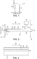
- the counting device 2 described below by way of example and represented diagrammatically in Figure 1 has a housing 4 and is kept in a pocket format.
- a further part of the counting device 2 is an actuating mechanism, which when actuated is accompanied by a plunger 8 being moved in the direction of the housing 4 along a predetermined displacement path, whereby on the one hand a gas pressure is built up, with the aid of which a restoring force is built up, and whereby on the other hand mechanical work is coupled into an assembly 10 with a bending transducer 12, so that as a result the work performed by a user of the counting device 2 through the movement of the plunger 8 is at least partially converted into electrical energy.
- This energy is used for supplying an electronic assembly 14 with a counting logic and for supplying a bistable (LCD) indicating element 16.
- the counting logic thereby counts backwards in the manner of a countdown from a starting value, each actuation of the actuating mechanism, that is to say each movement of the plunger 8 in the direction of the housing 4, being accompanied by generation of an energy pulse, on the basis of which the counting logic reduces the counter reading by one unit. Moreover, when there is a change in the counter reading, the bistable indicating element 16 is activated, so that it subsequently indicates the changed, and consequently current, counter reading.
- the counting logic is locked for a certain time with the aid of a timer, so that no changing of the counter reading takes place in this time period. It is assumed here that the user releases the plunger 8 again within this time period, the plunger being moved back into its initial position on account of a restoring force exerted by the assembly 10 on the plunger 8. With the aid of the locking of the counting logic, it is consequently prevented that the return of the plunger 8 leads to a changing of the counter reading.
- the assembly 10 for the conversion of mechanical work into electrical energy is depicted in its basic form in Figure 2 . It comprises the bending transducer 12 and a transducer circuit 18, with the aid of which a voltage picked off from the bending transducer 12 is converted into a supply voltage for the electronic assembly 14 on the one hand and for the indicating element 16 on the other.
- the transducer circuit 18 is, for example, part of the electronic assembly 14.
- Part of the bending transducer 12 is a support 20 in the form of a strip (for example with the dimensions 25 mm ⁇ 80 mm ⁇ 0.42 mm) of a composite material comprising fibreglass and synthetic resin, on which a piezoelectric layer 22 (for example with the dimensions 24 mm ⁇ 28 mm ⁇ 0.25 mm) is adhesively bonded in a middle region on the upper side of the support 20, facing the transducer circuit 18.
- a support 20 in the form of a strip (for example with the dimensions 25 mm ⁇ 80 mm ⁇ 0.42 mm) of a composite material comprising fibreglass and synthetic resin, on which a piezoelectric layer 22 (for example with the dimensions 24 mm ⁇ 28 mm ⁇ 0.25 mm) is adhesively bonded in a middle region on the upper side of the support 20, facing the transducer circuit 18.
- vapour-deposited on the upper side of the support 20 on the one hand and on the upper side of the piezoelectric layer 22 on the other hand are metallic electrodes, the extent of which transversely to the longitudinal direction of the support 26 corresponds to the extent of the piezoelectric layer 22 transversely to the longitudinal direction of the support 26 or exceeds it.
- the electrodes 24 are connected in an electrically conducting manner to the transducer circuit 18 by way for example of simple wire connections 28.
- the wire connections 28 allow a movement of the bending transducer 12 in relation to the transducer circuit 18, which is for example accommodated on a simple circuit board fastened to the housing 4, without the contacts between the wire connections 28 and the electrodes 24 being subjected to mechanical loading.
- the support 20 has a slightly arcuate curvature and is mounted at both ends.
- the support 20 lies with each of both ends loosely and with play in a holder 30, a receptacle being formed by a depression or groove in one of the walls of the housing 4 or a holding element, while the other holder 30 is provided by a profiled strip formed on the plunger 8 and reaching around the support 20. If the plunger 8 is thus moved in the longitudinal direction of the support 26 in the course of an actuation of the actuating mechanism, a mechanical force is exerted on the support 20 in the longitudinal direction of the support 26 after overcoming the play between the support 20 and the holders 30, whereby the support 20 arcuately bends. As a result of this, the piezoelectric layer 22 undergoes a tensile deformation, whereupon there forms a voltage that can be picked off from the piezoelectric layer 22.
- the support 20 and the housing 4 of the counting device 2 are not rigidly coupled to one another, whereby shock effects such as are caused for example when the counting device 2 is carried in a pocket on the body while walking or shock effects such as occur when it is dropped on the ground or put down on a table lead to a movement of the support 20 in relation to the housing 4, but not to a bending of the bending transducer 12.
- the assembly 10 and the electronic assembly 14 are in this case preferably designed in such a way that even a displacement of only a few millimetres, for example even 2-4 mm, is accompanied by generation of sufficient energy for the performance of the useful function.
- the bending transducer 12 is configured as a monomorphic bending transducer 12 and accordingly has precisely one piezoelectric layer 22.
- the material thicknesses of the support 20 on the one hand and of the piezoelectric layer 22 on the other hand are made to match one another in such a way that the neutral axis of the bending transducer lies within the support 20, and consequently outside the piezoelectric layer 22, so that as a result of this, when there is a bending of the bending transducer 12, a tensile deformation occurs in the entire piezoelectric layer 22, whereby the piezoelectric effect is particularly pronounced.
Landscapes
- Engineering & Computer Science (AREA)
- General Engineering & Computer Science (AREA)
- Physics & Mathematics (AREA)
- General Physics & Mathematics (AREA)
- Theoretical Computer Science (AREA)
- Architecture (AREA)
- General Electrical Machinery Utilizing Piezoelectricity, Electrostriction Or Magnetostriction (AREA)
- Force Measurement Appropriate To Specific Purposes (AREA)
Claims (12)
- Zählvorrichtung (2), aufweisend eine Anordnung (10) zur Umwandlung von mechanischer Arbeit in elektrische Energie, wobei die Anordnung einen Biegewandler (12) mit einem Träger (20) in Form eines Streifens und mit mindestens einer daran angebrachten piezoelektrischen Schicht (22) aufweist, wobei der Träger (20) in Form eines Streifens an beiden Enden (30) montiert ist und wobei ein Betätigungsmechanismus (8, 30) derart vorgesehen ist, dass, wenn der Betätigungsmechanismus (8, 30) betätigt wird, eine mechanische Kraft in Längsrichtung des Trägers (26) auf den Träger (20) ausgeübt wird und zu einem bogenförmigen Biegen des Biegewandlers (12) und damit zur Erzeugung von elektrischer Energie führt, wobei die Zählvorrichtung eine elektronische Anzeigevorrichtung (16) und eine elektronische Anordnung (14) zum Erfassen von Betätigungen des Betätigungsmechanismus (8, 30) und zum Steuern der elektronischen Anzeigeeinheit (16) aufweist, wobei die Anordnung (10) elektrische Energie für die elektronische Anordnung (14) und die elektronische Anzeigevorrichtung (16) liefert.
- Zählvorrichtung (2) gemäß Anspruch 1, wobei der Träger (20) in Form eines Streifens schwimmend (30) montiert ist.
- Zählvorrichtung (2) gemäß Anspruch 1 oder 2, wobei mindestens ein Ende des Trägers (20) in Form eines Streifens lose und mit einem Spiel in einem Halter (30) liegt.
- Zählvorrichtung (2) gemäß Anspruch 3, wobei die Bewegungsfreiheit, die durch das Spiel vorgesehen wird, 10 µm bis 500 µm in der Längsrichtung des Trägers (26) beträgt.
- Zählvorrichtung (2) nach einem der vorhergehenden Ansprüche, wobei der Träger (20) in Form eines Streifens eine bogenförmige Vorkrümmung aufweist.
- Zählvorrichtung (2) nach einem der vorhergehenden Ansprüche, wobei genau eine piezoelektrische Schicht (22) auf dem Träger in Form eines Streifens aufgebracht ist, wobei die piezoelektrische Schicht (22) eine Zugverformung erfährt, wenn der Betätigungsmechanismus (8, 30) betätigt wird.
- Zählvorrichtung (2) nach einem der vorhergehenden Ansprüche, wobei die piezoelektrische Schicht (22) des Biegewandlers (12) außerhalb einer Biegeachse des Biegewandlers (12) positioniert ist.
- Zählvorrichtung (2) nach einem der vorhergehenden Ansprüche, wobei der Biegewandler (12) mindestens zwei Elektroden (24) aufweist, wobei die Elektroden (24) außerhalb der Endhalterungen (30) des Trägers (20) zum Bilden einer elektrischen Verbindung (28) zwischen der piezoelektrischen Schicht (22) des Biegewandlers (12) und einer Wandlerschaltung (18) mit Leitern (28) verbunden ist.
- Zählvorrichtung (2) nach einem der vorhergehenden Ansprüche, wobei jede vollständig ausgeführte Betätigung des Betätigungsmechanismus (8, 30) von der Ausführung einer Arbeitsperiode begleitet wird, bei der ein elektrischer Energieimpuls erzeugt und für die Versorgung einer elektronischen Anordnung (14) verwendet wird, wobei der Energiegehalt eines Energieimpulses für eine nützliche Funktion der elektronischen Anordnung (14) zur einmaligen Ausführung ausgelegt ist.
- Zählvorrichtung (2) gemäß Anspruch 9, wobei ein Energiegehalt der elektrischen Impulsenergie wenige 10 µJ bis wenige 100 µJ beträgt.
- Zählvorrichtung (2) gemäß Anspruch 9, wobei die Arbeitsperiode aus einer aktiven Halbperiode und einer passiven Halbperiode besteht, wobei zumindest die aktive Halbperiode von der Erzeugung eines elektrischen Energieimpulses begleitet ist, dessen Energiegehalt ausreichend ist, um einmalig eine nützliche Funktion der elektronischen Anordnung (14) auszuführen.
- Zählvorrichtung (2) gemäß Anspruch 11, wobei die elektronische Anordnung (14) derart ausgeführt ist, dass die Ausführung der nützlichen Funktion durch die passive Halbperiode blockiert wird.
Applications Claiming Priority (2)
| Application Number | Priority Date | Filing Date | Title |
|---|---|---|---|
| DE102012220697.3A DE102012220697A1 (de) | 2012-11-13 | 2012-11-13 | Baugruppe zur Wandlung von mechanischer Arbeit in elektrische Energie und Zählvorrichtung mit entsprechender Baugruppe |
| PCT/GB2013/052946 WO2014076458A1 (en) | 2012-11-13 | 2013-11-08 | Assembly for converting mechanical work into electrical energy and counting device comprising it |
Publications (2)
| Publication Number | Publication Date |
|---|---|
| EP2920826A1 EP2920826A1 (de) | 2015-09-23 |
| EP2920826B1 true EP2920826B1 (de) | 2018-03-14 |
Family
ID=49759439
Family Applications (1)
| Application Number | Title | Priority Date | Filing Date |
|---|---|---|---|
| EP13803192.7A Not-in-force EP2920826B1 (de) | 2012-11-13 | 2013-11-08 | Anordnung zur umwandlung von mechanischer arbeit in elektrische energie und zählvorrichtung damit |
Country Status (6)
| Country | Link |
|---|---|
| US (1) | US20160294307A1 (de) |
| EP (1) | EP2920826B1 (de) |
| JP (1) | JP2016504896A (de) |
| CN (1) | CN104798217B (de) |
| DE (2) | DE102012220697A1 (de) |
| WO (1) | WO2014076458A1 (de) |
Families Citing this family (9)
| Publication number | Priority date | Publication date | Assignee | Title |
|---|---|---|---|---|
| WO2015044422A1 (en) | 2013-09-29 | 2015-04-02 | Institut Hospitalo-Universitaire De Chirurgie Mini-Invasive Guidee Par L'image | Iimplantable device to treat obesity |
| DE102014212525A1 (de) | 2014-06-27 | 2015-12-31 | Johnson Matthey Catalysts (Germany) Gmbh | Vorrichtung, insbesondere Dosiereinheit |
| US10447177B2 (en) | 2015-08-13 | 2019-10-15 | The Regents Of The University Of Michigan | Energy harvesting from constrained buckling of piezoelectric beams |
| DE102016203520A1 (de) | 2016-03-03 | 2017-09-07 | Volkswagen Aktiengesellschaft | Gehäuse, beispielsweise für eine Funkfernbedienung oder einen Fahrzeugschlüssel und Funkfernbedienung |
| US11736042B2 (en) | 2018-04-09 | 2023-08-22 | King Abdullah University Of Science And Technology | Energy producing device with a piezoelectric energy generating beam |
| CN108540014B (zh) * | 2018-05-14 | 2020-03-24 | 中国科学院上海微系统与信息技术研究所 | 一种低频柔性能量采集器和自供能运动计数器 |
| CN109492742A (zh) * | 2018-11-06 | 2019-03-19 | 宁波工程学院 | 一种自发电无源计数装置 |
| CN109858601A (zh) * | 2019-03-06 | 2019-06-07 | 北京理工大学 | 一种基于机械能的能传合一计数系统 |
| DE102019118869B4 (de) * | 2019-07-11 | 2021-01-21 | Aesculap Ag | Vorrichtung zur Erfassung von Betätigungszyklen eines handbetätigten Instruments |
Family Cites Families (19)
| Publication number | Priority date | Publication date | Assignee | Title |
|---|---|---|---|---|
| JP2002354853A (ja) * | 1997-08-04 | 2002-12-06 | Seiko Epson Corp | アクチュエータ、およびそれを用いた時計並びに報知装置 |
| JP2000346863A (ja) * | 1999-06-04 | 2000-12-15 | Suzuki Sogyo Co Ltd | カウント表示装置用のカウンタ素子及びカウント表示装置付き運動具 |
| US7231874B2 (en) * | 2001-09-05 | 2007-06-19 | Omnitek Partners Llc | Power supplies for projectiles and other devices |
| DE10349357A1 (de) * | 2002-12-27 | 2004-07-08 | Werfel, Frank, Dr. | Verfahren und Einrichtung zur mobilen Energiegewinnung und -speicherung sowie zur Erfassung und Auswertung von Messwerten körpericher Bewegungsabläufe |
| JP2005312269A (ja) * | 2004-04-26 | 2005-11-04 | Nec Corp | 振動による発電方法および振動式発電機および振動式発電装置 |
| EP1803168A4 (de) * | 2004-10-21 | 2009-05-20 | Michelin Soc Tech | Miniaturisierte, auf piezoelektrik basierende vibrationsenergie-sammelvorrichtung |
| DE102004055996A1 (de) * | 2004-11-19 | 2006-05-24 | Stefan Eickenberg | Biegeaktuator |
| JP3768520B1 (ja) * | 2005-04-13 | 2006-04-19 | 太平洋セメント株式会社 | 発電装置 |
| JP3806724B1 (ja) * | 2005-05-16 | 2006-08-09 | 太平洋セメント株式会社 | 発光装置及びそれを用いた懐中電灯 |
| KR20080070629A (ko) | 2005-09-23 | 2008-07-30 | 더 리전츠 오브 더 유니버시티 오브 캘리포니아 | 주파수 정류를 이용한 에너지 수확장치 |
| US7439657B2 (en) * | 2006-10-20 | 2008-10-21 | The Boeing Company | Broadband energy harvester apparatus and method |
| US8432057B2 (en) * | 2007-05-01 | 2013-04-30 | Pliant Energy Systems Llc | Pliant or compliant elements for harnessing the forces of moving fluid to transport fluid or generate electricity |
| US8354776B2 (en) * | 2008-12-22 | 2013-01-15 | Samsung Electronics Co., Ltd. | Apparatus for generating electrical energy and method for manufacturing the same |
| EP2456971B1 (de) * | 2009-07-21 | 2015-08-19 | Pliant Energy Systems Llc | Biegsamer mechanismus zur umwandlung von energie aus einer flüssigkeit in bewegung |
| DE102009058984A1 (de) * | 2009-12-18 | 2011-06-22 | Robert Bosch GmbH, 70469 | Elektroaktiver Polymergenerator zur Wandlung von mechanischer Energie in elektrische Energie |
| US8212436B2 (en) * | 2010-02-01 | 2012-07-03 | Oscilla Power, Inc. | Apparatus for harvesting electrical power from mechanical energy |
| CN103201867B (zh) * | 2010-11-04 | 2016-08-03 | 阿尔格拉控股有限公司 | 压电信号生成器 |
| JP2012191812A (ja) * | 2011-03-14 | 2012-10-04 | Seiko Epson Corp | 発電装置、および電子機器 |
| DE102012211576B4 (de) | 2012-07-04 | 2015-02-12 | Johnson Matthey Catalysts (Germany) Gmbh | Vorrichtung sowie Verfahren zur Verwaltung und Bereitstellung der von einer Energieerzeugungseinheit gewonnenen Kleinstenergiemenge |
-
2012
- 2012-11-13 DE DE102012220697.3A patent/DE102012220697A1/de not_active Ceased
- 2012-11-13 DE DE202012012758.6U patent/DE202012012758U1/de not_active Expired - Lifetime
-
2013
- 2013-11-08 CN CN201380059208.4A patent/CN104798217B/zh not_active Expired - Fee Related
- 2013-11-08 JP JP2015541233A patent/JP2016504896A/ja active Pending
- 2013-11-08 EP EP13803192.7A patent/EP2920826B1/de not_active Not-in-force
- 2013-11-08 WO PCT/GB2013/052946 patent/WO2014076458A1/en not_active Ceased
- 2013-11-08 US US14/442,118 patent/US20160294307A1/en not_active Abandoned
Also Published As
| Publication number | Publication date |
|---|---|
| US20160294307A1 (en) | 2016-10-06 |
| DE202012012758U1 (de) | 2014-02-18 |
| EP2920826A1 (de) | 2015-09-23 |
| CN104798217B (zh) | 2017-11-07 |
| JP2016504896A (ja) | 2016-02-12 |
| CN104798217A (zh) | 2015-07-22 |
| WO2014076458A1 (en) | 2014-05-22 |
| DE102012220697A1 (de) | 2014-05-15 |
Similar Documents
| Publication | Publication Date | Title |
|---|---|---|
| US20160294307A1 (en) | Assembly for converting mechanical work into electrical energy and counting device comprising it | |
| US10422166B2 (en) | Piezo based energy harvesting for E-latch systems | |
| US8803670B2 (en) | Operating control having specific feedback | |
| CN1689218B (zh) | 能量自给的机电式无线电开关 | |
| US20050253486A1 (en) | Device for converting mechanical energy into electrical energy | |
| EP2323015A2 (de) | Manuelle Steuervorrichtung mit Energieerzeugungsfunktion und Fernbedienungsvorrichtung mit Energieerzeugungsfunktion | |
| EP1763048A1 (de) | Schalteinrichtung | |
| CN112368670A (zh) | 用于产生触觉信号的装置 | |
| EP2143040A2 (de) | Verschiedene aspekte elektronischer stifte | |
| JP2005509297A (ja) | 機械的エネルギーを電気的エネルギーに変換する装置 | |
| US12050732B2 (en) | Integrated virtual button module, integrated virtual button system, and method of determining user input and providing user feedback | |
| US20030016089A1 (en) | Use of a piezo-active device and an appliance and a system including it | |
| CN108475132A (zh) | 输入装置 | |
| CN102780418B (zh) | 一种自供电遥控装置 | |
| JPH10125204A (ja) | スイッチ | |
| KR101682911B1 (ko) | 발전 장치 및 이를 이용한 자가 발전식 센싱 장치 | |
| JP2006262575A (ja) | 発電装置 | |
| CN112696105B (zh) | 用于门解锁和/或开门机构的操纵装置 | |
| JP2005040485A (ja) | スライドファスナー | |
| JP2013132192A (ja) | 発電装置 | |
| KR101790923B1 (ko) | 기계적 타이머 기능을 갖는 칫솔 | |
| JP7586996B2 (ja) | 衝撃に耐えるように構成している、電子機器を制御するための制御モジュール | |
| US7504761B2 (en) | Driving device | |
| EP2034465A3 (de) | Elektronische Vorrichtung | |
| US20090243434A1 (en) | Shock recognition system in a doorlock |
Legal Events
| Date | Code | Title | Description |
|---|---|---|---|
| PUAI | Public reference made under article 153(3) epc to a published international application that has entered the european phase |
Free format text: ORIGINAL CODE: 0009012 |
|
| 17P | Request for examination filed |
Effective date: 20150428 |
|
| AK | Designated contracting states |
Kind code of ref document: A1 Designated state(s): AL AT BE BG CH CY CZ DE DK EE ES FI FR GB GR HR HU IE IS IT LI LT LU LV MC MK MT NL NO PL PT RO RS SE SI SK SM TR |
|
| AX | Request for extension of the european patent |
Extension state: BA ME |
|
| DAX | Request for extension of the european patent (deleted) | ||
| RIC1 | Information provided on ipc code assigned before grant |
Ipc: H02N 2/18 20060101ALI20160601BHEP Ipc: H01L 41/113 20060101AFI20160601BHEP Ipc: G06M 1/10 20060101ALI20160601BHEP |
|
| 17Q | First examination report despatched |
Effective date: 20160613 |
|
| GRAP | Despatch of communication of intention to grant a patent |
Free format text: ORIGINAL CODE: EPIDOSNIGR1 |
|
| STAA | Information on the status of an ep patent application or granted ep patent |
Free format text: STATUS: GRANT OF PATENT IS INTENDED |
|
| INTG | Intention to grant announced |
Effective date: 20170224 |
|
| GRAS | Grant fee paid |
Free format text: ORIGINAL CODE: EPIDOSNIGR3 |
|
| GRAA | (expected) grant |
Free format text: ORIGINAL CODE: 0009210 |
|
| STAA | Information on the status of an ep patent application or granted ep patent |
Free format text: STATUS: THE PATENT HAS BEEN GRANTED |
|
| AK | Designated contracting states |
Kind code of ref document: B1 Designated state(s): AL AT BE BG CH CY CZ DE DK EE ES FI FR GB GR HR HU IE IS IT LI LT LU LV MC MK MT NL NO PL PT RO RS SE SI SK SM TR |
|
| REG | Reference to a national code |
Ref country code: GB Ref legal event code: FG4D |
|
| REG | Reference to a national code |
Ref country code: CH Ref legal event code: EP Ref country code: AT Ref legal event code: REF Ref document number: 979654 Country of ref document: AT Kind code of ref document: T Effective date: 20180315 |
|
| REG | Reference to a national code |
Ref country code: IE Ref legal event code: FG4D |
|
| REG | Reference to a national code |
Ref country code: DE Ref legal event code: R096 Ref document number: 602013034465 Country of ref document: DE |
|
| REG | Reference to a national code |
Ref country code: NL Ref legal event code: MP Effective date: 20180314 |
|
| REG | Reference to a national code |
Ref country code: LT Ref legal event code: MG4D |
|
| PG25 | Lapsed in a contracting state [announced via postgrant information from national office to epo] |
Ref country code: CY Free format text: LAPSE BECAUSE OF FAILURE TO SUBMIT A TRANSLATION OF THE DESCRIPTION OR TO PAY THE FEE WITHIN THE PRESCRIBED TIME-LIMIT Effective date: 20180314 Ref country code: NO Free format text: LAPSE BECAUSE OF FAILURE TO SUBMIT A TRANSLATION OF THE DESCRIPTION OR TO PAY THE FEE WITHIN THE PRESCRIBED TIME-LIMIT Effective date: 20180614 Ref country code: FI Free format text: LAPSE BECAUSE OF FAILURE TO SUBMIT A TRANSLATION OF THE DESCRIPTION OR TO PAY THE FEE WITHIN THE PRESCRIBED TIME-LIMIT Effective date: 20180314 Ref country code: LT Free format text: LAPSE BECAUSE OF FAILURE TO SUBMIT A TRANSLATION OF THE DESCRIPTION OR TO PAY THE FEE WITHIN THE PRESCRIBED TIME-LIMIT Effective date: 20180314 Ref country code: HR Free format text: LAPSE BECAUSE OF FAILURE TO SUBMIT A TRANSLATION OF THE DESCRIPTION OR TO PAY THE FEE WITHIN THE PRESCRIBED TIME-LIMIT Effective date: 20180314 |
|
| REG | Reference to a national code |
Ref country code: AT Ref legal event code: MK05 Ref document number: 979654 Country of ref document: AT Kind code of ref document: T Effective date: 20180314 |
|
| PG25 | Lapsed in a contracting state [announced via postgrant information from national office to epo] |
Ref country code: LV Free format text: LAPSE BECAUSE OF FAILURE TO SUBMIT A TRANSLATION OF THE DESCRIPTION OR TO PAY THE FEE WITHIN THE PRESCRIBED TIME-LIMIT Effective date: 20180314 Ref country code: SE Free format text: LAPSE BECAUSE OF FAILURE TO SUBMIT A TRANSLATION OF THE DESCRIPTION OR TO PAY THE FEE WITHIN THE PRESCRIBED TIME-LIMIT Effective date: 20180314 Ref country code: RS Free format text: LAPSE BECAUSE OF FAILURE TO SUBMIT A TRANSLATION OF THE DESCRIPTION OR TO PAY THE FEE WITHIN THE PRESCRIBED TIME-LIMIT Effective date: 20180314 Ref country code: GR Free format text: LAPSE BECAUSE OF FAILURE TO SUBMIT A TRANSLATION OF THE DESCRIPTION OR TO PAY THE FEE WITHIN THE PRESCRIBED TIME-LIMIT Effective date: 20180615 Ref country code: BG Free format text: LAPSE BECAUSE OF FAILURE TO SUBMIT A TRANSLATION OF THE DESCRIPTION OR TO PAY THE FEE WITHIN THE PRESCRIBED TIME-LIMIT Effective date: 20180614 |
|
| PG25 | Lapsed in a contracting state [announced via postgrant information from national office to epo] |
Ref country code: IT Free format text: LAPSE BECAUSE OF FAILURE TO SUBMIT A TRANSLATION OF THE DESCRIPTION OR TO PAY THE FEE WITHIN THE PRESCRIBED TIME-LIMIT Effective date: 20180314 Ref country code: ES Free format text: LAPSE BECAUSE OF FAILURE TO SUBMIT A TRANSLATION OF THE DESCRIPTION OR TO PAY THE FEE WITHIN THE PRESCRIBED TIME-LIMIT Effective date: 20180314 Ref country code: RO Free format text: LAPSE BECAUSE OF FAILURE TO SUBMIT A TRANSLATION OF THE DESCRIPTION OR TO PAY THE FEE WITHIN THE PRESCRIBED TIME-LIMIT Effective date: 20180314 Ref country code: NL Free format text: LAPSE BECAUSE OF FAILURE TO SUBMIT A TRANSLATION OF THE DESCRIPTION OR TO PAY THE FEE WITHIN THE PRESCRIBED TIME-LIMIT Effective date: 20180314 Ref country code: PL Free format text: LAPSE BECAUSE OF FAILURE TO SUBMIT A TRANSLATION OF THE DESCRIPTION OR TO PAY THE FEE WITHIN THE PRESCRIBED TIME-LIMIT Effective date: 20180314 Ref country code: EE Free format text: LAPSE BECAUSE OF FAILURE TO SUBMIT A TRANSLATION OF THE DESCRIPTION OR TO PAY THE FEE WITHIN THE PRESCRIBED TIME-LIMIT Effective date: 20180314 Ref country code: AL Free format text: LAPSE BECAUSE OF FAILURE TO SUBMIT A TRANSLATION OF THE DESCRIPTION OR TO PAY THE FEE WITHIN THE PRESCRIBED TIME-LIMIT Effective date: 20180314 |
|
| PG25 | Lapsed in a contracting state [announced via postgrant information from national office to epo] |
Ref country code: SM Free format text: LAPSE BECAUSE OF FAILURE TO SUBMIT A TRANSLATION OF THE DESCRIPTION OR TO PAY THE FEE WITHIN THE PRESCRIBED TIME-LIMIT Effective date: 20180314 Ref country code: AT Free format text: LAPSE BECAUSE OF FAILURE TO SUBMIT A TRANSLATION OF THE DESCRIPTION OR TO PAY THE FEE WITHIN THE PRESCRIBED TIME-LIMIT Effective date: 20180314 Ref country code: SK Free format text: LAPSE BECAUSE OF FAILURE TO SUBMIT A TRANSLATION OF THE DESCRIPTION OR TO PAY THE FEE WITHIN THE PRESCRIBED TIME-LIMIT Effective date: 20180314 Ref country code: CZ Free format text: LAPSE BECAUSE OF FAILURE TO SUBMIT A TRANSLATION OF THE DESCRIPTION OR TO PAY THE FEE WITHIN THE PRESCRIBED TIME-LIMIT Effective date: 20180314 |
|
| REG | Reference to a national code |
Ref country code: DE Ref legal event code: R097 Ref document number: 602013034465 Country of ref document: DE |
|
| PG25 | Lapsed in a contracting state [announced via postgrant information from national office to epo] |
Ref country code: PT Free format text: LAPSE BECAUSE OF FAILURE TO SUBMIT A TRANSLATION OF THE DESCRIPTION OR TO PAY THE FEE WITHIN THE PRESCRIBED TIME-LIMIT Effective date: 20180716 |
|
| PLBE | No opposition filed within time limit |
Free format text: ORIGINAL CODE: 0009261 |
|
| STAA | Information on the status of an ep patent application or granted ep patent |
Free format text: STATUS: NO OPPOSITION FILED WITHIN TIME LIMIT |
|
| PG25 | Lapsed in a contracting state [announced via postgrant information from national office to epo] |
Ref country code: DK Free format text: LAPSE BECAUSE OF FAILURE TO SUBMIT A TRANSLATION OF THE DESCRIPTION OR TO PAY THE FEE WITHIN THE PRESCRIBED TIME-LIMIT Effective date: 20180314 |
|
| 26N | No opposition filed |
Effective date: 20181217 |
|
| PG25 | Lapsed in a contracting state [announced via postgrant information from national office to epo] |
Ref country code: SI Free format text: LAPSE BECAUSE OF FAILURE TO SUBMIT A TRANSLATION OF THE DESCRIPTION OR TO PAY THE FEE WITHIN THE PRESCRIBED TIME-LIMIT Effective date: 20180314 |
|
| REG | Reference to a national code |
Ref country code: DE Ref legal event code: R119 Ref document number: 602013034465 Country of ref document: DE |
|
| REG | Reference to a national code |
Ref country code: CH Ref legal event code: PL |
|
| GBPC | Gb: european patent ceased through non-payment of renewal fee |
Effective date: 20181108 |
|
| PG25 | Lapsed in a contracting state [announced via postgrant information from national office to epo] |
Ref country code: MC Free format text: LAPSE BECAUSE OF FAILURE TO SUBMIT A TRANSLATION OF THE DESCRIPTION OR TO PAY THE FEE WITHIN THE PRESCRIBED TIME-LIMIT Effective date: 20180314 Ref country code: LU Free format text: LAPSE BECAUSE OF NON-PAYMENT OF DUE FEES Effective date: 20181108 |
|
| REG | Reference to a national code |
Ref country code: BE Ref legal event code: MM Effective date: 20181130 |
|
| REG | Reference to a national code |
Ref country code: IE Ref legal event code: MM4A |
|
| PG25 | Lapsed in a contracting state [announced via postgrant information from national office to epo] |
Ref country code: LI Free format text: LAPSE BECAUSE OF NON-PAYMENT OF DUE FEES Effective date: 20181130 Ref country code: CH Free format text: LAPSE BECAUSE OF NON-PAYMENT OF DUE FEES Effective date: 20181130 |
|
| PG25 | Lapsed in a contracting state [announced via postgrant information from national office to epo] |
Ref country code: FR Free format text: LAPSE BECAUSE OF NON-PAYMENT OF DUE FEES Effective date: 20181130 Ref country code: DE Free format text: LAPSE BECAUSE OF NON-PAYMENT OF DUE FEES Effective date: 20190601 Ref country code: IE Free format text: LAPSE BECAUSE OF NON-PAYMENT OF DUE FEES Effective date: 20181108 |
|
| PG25 | Lapsed in a contracting state [announced via postgrant information from national office to epo] |
Ref country code: BE Free format text: LAPSE BECAUSE OF NON-PAYMENT OF DUE FEES Effective date: 20181130 |
|
| PG25 | Lapsed in a contracting state [announced via postgrant information from national office to epo] |
Ref country code: GB Free format text: LAPSE BECAUSE OF NON-PAYMENT OF DUE FEES Effective date: 20181108 |
|
| PG25 | Lapsed in a contracting state [announced via postgrant information from national office to epo] |
Ref country code: MT Free format text: LAPSE BECAUSE OF NON-PAYMENT OF DUE FEES Effective date: 20181108 |
|
| PG25 | Lapsed in a contracting state [announced via postgrant information from national office to epo] |
Ref country code: TR Free format text: LAPSE BECAUSE OF FAILURE TO SUBMIT A TRANSLATION OF THE DESCRIPTION OR TO PAY THE FEE WITHIN THE PRESCRIBED TIME-LIMIT Effective date: 20180314 |
|
| PG25 | Lapsed in a contracting state [announced via postgrant information from national office to epo] |
Ref country code: HU Free format text: LAPSE BECAUSE OF FAILURE TO SUBMIT A TRANSLATION OF THE DESCRIPTION OR TO PAY THE FEE WITHIN THE PRESCRIBED TIME-LIMIT; INVALID AB INITIO Effective date: 20131108 Ref country code: MK Free format text: LAPSE BECAUSE OF NON-PAYMENT OF DUE FEES Effective date: 20180314 |
|
| PG25 | Lapsed in a contracting state [announced via postgrant information from national office to epo] |
Ref country code: IS Free format text: LAPSE BECAUSE OF FAILURE TO SUBMIT A TRANSLATION OF THE DESCRIPTION OR TO PAY THE FEE WITHIN THE PRESCRIBED TIME-LIMIT Effective date: 20180714 |