EP2920857B1 - Circuit de protection pour transformateur de courant et transformateur de courant comprenant un circuit de protection - Google Patents
Circuit de protection pour transformateur de courant et transformateur de courant comprenant un circuit de protection Download PDFInfo
- Publication number
- EP2920857B1 EP2920857B1 EP13789278.2A EP13789278A EP2920857B1 EP 2920857 B1 EP2920857 B1 EP 2920857B1 EP 13789278 A EP13789278 A EP 13789278A EP 2920857 B1 EP2920857 B1 EP 2920857B1
- Authority
- EP
- European Patent Office
- Prior art keywords
- voltage
- protective circuit
- input
- circuit
- unit
- Prior art date
- Legal status (The legal status is an assumption and is not a legal conclusion. Google has not performed a legal analysis and makes no representation as to the accuracy of the status listed.)
- Active
Links
Images

Classifications
-
- H—ELECTRICITY
- H02—GENERATION; CONVERSION OR DISTRIBUTION OF ELECTRIC POWER
- H02H—EMERGENCY PROTECTIVE CIRCUIT ARRANGEMENTS
- H02H9/00—Emergency protective circuit arrangements for limiting excess current or voltage without disconnection
- H02H9/04—Emergency protective circuit arrangements for limiting excess current or voltage without disconnection responsive to excess voltage
- H02H9/041—Emergency protective circuit arrangements for limiting excess current or voltage without disconnection responsive to excess voltage using a short-circuiting device
-
- G—PHYSICS
- G01—MEASURING; TESTING
- G01R—MEASURING ELECTRIC VARIABLES; MEASURING MAGNETIC VARIABLES
- G01R1/00—Details of instruments or arrangements of the types included in groups G01R5/00 - G01R13/00 and G01R31/00
- G01R1/36—Overload-protection arrangements or circuits for electric measuring instruments
-
- H—ELECTRICITY
- H01—ELECTRIC ELEMENTS
- H01F—MAGNETS; INDUCTANCES; TRANSFORMERS; SELECTION OF MATERIALS FOR THEIR MAGNETIC PROPERTIES
- H01F38/00—Adaptations of transformers or inductances for specific applications or functions
- H01F38/20—Instruments transformers
- H01F38/22—Instruments transformers for single phase AC
- H01F38/28—Current transformers
- H01F38/32—Circuit arrangements
-
- H—ELECTRICITY
- H02—GENERATION; CONVERSION OR DISTRIBUTION OF ELECTRIC POWER
- H02H—EMERGENCY PROTECTIVE CIRCUIT ARRANGEMENTS
- H02H7/00—Emergency protective circuit arrangements specially adapted for specific types of electric machines or apparatus or for sectionalised protection of cable or line systems, and effecting automatic switching in the event of an undesired change from normal working conditions
- H02H7/04—Emergency protective circuit arrangements specially adapted for specific types of electric machines or apparatus or for sectionalised protection of cable or line systems, and effecting automatic switching in the event of an undesired change from normal working conditions for transformers
- H02H7/042—Emergency protective circuit arrangements specially adapted for specific types of electric machines or apparatus or for sectionalised protection of cable or line systems, and effecting automatic switching in the event of an undesired change from normal working conditions for transformers for current transformers
-
- H—ELECTRICITY
- H02—GENERATION; CONVERSION OR DISTRIBUTION OF ELECTRIC POWER
- H02H—EMERGENCY PROTECTIVE CIRCUIT ARRANGEMENTS
- H02H9/00—Emergency protective circuit arrangements for limiting excess current or voltage without disconnection
- H02H9/04—Emergency protective circuit arrangements for limiting excess current or voltage without disconnection responsive to excess voltage
- H02H9/043—Protection of over-voltage protection device by short-circuiting
-
- H—ELECTRICITY
- H03—ELECTRONIC CIRCUITRY
- H03K—PULSE TECHNIQUE
- H03K17/00—Electronic switching or gating, i.e. not by contact-making and –breaking
- H03K17/08—Modifications for protecting switching circuit against overcurrent or overvoltage
- H03K17/082—Modifications for protecting switching circuit against overcurrent or overvoltage by feedback from the output to the control circuit
- H03K17/0822—Modifications for protecting switching circuit against overcurrent or overvoltage by feedback from the output to the control circuit in field-effect transistor switches
-
- G—PHYSICS
- G01—MEASURING; TESTING
- G01R—MEASURING ELECTRIC VARIABLES; MEASURING MAGNETIC VARIABLES
- G01R15/00—Details of measuring arrangements of the types provided for in groups G01R17/00 - G01R29/00, G01R33/00 - G01R33/26 or G01R35/00
- G01R15/14—Adaptations providing voltage or current isolation, e.g. for high-voltage or high-current networks
- G01R15/18—Adaptations providing voltage or current isolation, e.g. for high-voltage or high-current networks using inductive devices, e.g. transformers
- G01R15/183—Adaptations providing voltage or current isolation, e.g. for high-voltage or high-current networks using inductive devices, e.g. transformers using transformers with a magnetic core
-
- H—ELECTRICITY
- H01—ELECTRIC ELEMENTS
- H01F—MAGNETS; INDUCTANCES; TRANSFORMERS; SELECTION OF MATERIALS FOR THEIR MAGNETIC PROPERTIES
- H01F27/00—Details of transformers or inductances, in general
- H01F27/40—Structural association with built-in electric component, e.g. fuse
- H01F2027/408—Association with diode or rectifier
-
- H—ELECTRICITY
- H01—ELECTRIC ELEMENTS
- H01F—MAGNETS; INDUCTANCES; TRANSFORMERS; SELECTION OF MATERIALS FOR THEIR MAGNETIC PROPERTIES
- H01F27/00—Details of transformers or inductances, in general
- H01F27/40—Structural association with built-in electric component, e.g. fuse
- H01F27/402—Association of measuring or protective means
Definitions
- the invention relates to a protective circuit for a current transformer for preventing a secondary voltage on a secondary circuit of the current transformer from exceeding a secondary voltage threshold value.
- the invention also relates to a current converter with a protective circuit.
- the voltage peaks that occur with an open secondary circuit of the current transformer can be very high and therefore life-threatening and can also lead to the destruction of the current transformer.
- devices are known that short-circuit without delay, for example by means of diodes or relays, or with a delay.
- delayed short circuit are Designs are known which short-circuit periodically, for example by means of a thermistor, or continuously, for example after a spacer has softened.
- Relays can be designed in such a way that they release the current transformer secondary circuit automatically and without any major delay after the interruption has been eliminated.
- a circuit breaker in which a voltage-dependent circuit element actuates a switch fed by the current transformer when impermissibly high secondary voltages occur.
- Parallel to the secondary winding and the burden of the converter is a series connection of two anti-parallel connected rectifiers and a relay designed as a thermal relay. If the secondary voltage reaches a critical value, the relay responds and closes a contact that creates a short-circuit path that either bridges the rectifier or the series connection of rectifiers and relays.
- circuit breaker has a high level of inertia, so that both the response and the restoration of the normal operating state after the impermissibly high secondary voltage has subsided are carried out with a time delay. Furthermore, due to its size, such a circuit breaker can only be accommodated with difficulty in the secondary terminal box of the current transformer, is also expensive and is problematic in terms of operational safety.
- EP 1 304 786 A1 shows a voltage limiter for limiting short-term or long-term overvoltages with a varistor and a discharge path that can be switched parallel to the varistor.
- US patent application US 2012/0243136 A1 shows an overvoltage protection device for electrical circuits with a switch, the excess energy being stored in a reactive component.
- German Offenlegungsschrift DE 10 2007 008 264 A1 shows a circuit arrangement with a bidirectionally blocking semiconductor relay, which is a normally-off MOSFET. It is used there to avoid the use of a further semiconductor component in the opposite direction.
- the invention is based on the object of providing a protection circuit for a current transformer with regard to a higher response speed, higher load current, higher To further develop operational reliability, lower construction volume and lower manufacturing costs.
- the current transformer is essentially a short-circuited transformer that is used for potential-free measurement of alternating currents. It is primarily used to feed electricity meters or energy meters.
- the primary winding of the current transformer often consists of a single turn, for example a copper bar, while the secondary winding has a higher number of turns. This means that when the system is idling, the voltage in the primary circuit is transformed to an even higher voltage in the secondary circuit. The high voltage in the secondary circuit can endanger people or destroy the current transformer.
- the protective circuit serves to prevent a secondary voltage on a secondary circuit of the current transformer from exceeding a secondary voltage threshold value.
- the secondary voltage threshold value can, for example, have a value preset during the production of the protective circuit or a value that can be set by an operator.
- the protective circuit has a protective circuit input, preferably in the form of contact pins or a pair of terminals, which can be coupled to the secondary circuit of the current transformer, so that the secondary voltage is applied to the protective circuit input.
- the protective circuit further comprises a control unit connected to the protective circuit input, as well as a switch unit connected to the protective circuit input, which is controllably connected to the control unit.
- the control unit is designed to provide a control signal to the switch unit in response to the secondary voltage exceeding the secondary voltage threshold value.
- the value of the secondary voltage which is compared with the secondary voltage threshold value, can be an amplitude, a mean value, instantaneous value or effective value of the secondary voltage.
- the control unit can be implemented in the form of an electronic circuit, for example on a semiconductor basis, in particular in the form of an integrated circuit.
- the switch unit is designed to short-circuit the protective circuit input in response to the control signal provided by the control unit.
- the control signal can be provided on the line connecting the control unit to the switch unit in the form of a voltage which changes its value when the secondary voltage threshold is exceeded or in response to it being exceeded, for example from LOW to HIGH or vice versa.
- Short-circuiting the protective circuit input can be understood to mean that the switching element assumes a low resistance of less than 10 ⁇ , or 1 ⁇ , or 0.1 ⁇ , which is thus connected to the protective circuit input.
- the switch unit according to the invention is designed as a semiconductor circuit.
- the semiconductor circuit can preferably be designed as a semiconductor switch or semiconductor relay.
- a semiconductor switch can be understood to mean a switch implemented on a semiconductor basis.
- a semiconductor relay can be understood as a relay implemented on a semiconductor basis.
- the switch unit has two MOSFETs arranged anti-serially in a back-to-back circuit, which are connected to one another at a center connection.
- the drain connections of the transistors can each be connected to the terminals of the protective circuit input, and the gates can be connected to the control unit for supplying the control signal.
- the back-to-back circuit can advantageously be used for very high currents.
- the back-to-back circuit is capable of alternating voltage, since current can flow in both directions.
- the control unit further comprises a rectifier connected to the protective circuit input for providing a direct voltage that is dependent on an amplitude of the secondary voltage, in particular a pulsating direct voltage, as the input voltage of the comparator unit.
- the rectifier advantageously enables the control unit to react both during negative and positive half-waves of the secondary voltage, which enables the reaction time to be shortened further.
- the rectifier has four bridge branches, with two bridge branches providing the direct voltage.
- Two bridge displays of the rectifier are connected to the center connection of the switch unit.
- Another aspect of the invention relates to a current transformer, preferably a straight-through transformer, in which a protective circuit as described above is integrated.
- control unit and switch unit are related, inter alia, to the implementation of the control unit and switch unit on a semiconductor basis.
- control unit can be connected directly to the protection circuit input.
- the switch unit can be connected directly to the protective circuit input.
- directly connected means that the “control unit” and / or “switch unit” component is directly coupled or connected to the protective circuit input, with no electrical or mechanical elements between the component and the protective circuit input.
- the protective circuit can comprise a limiting unit, connected to the protective circuit input, for overvoltage protection.
- the limiting unit can comprise a voltage-dependent resistor.
- the voltage-dependent resistance has a constant value as long as the voltage applied to the limiting unit is below a threshold value. If the voltage exceeds the threshold value, the resistor reduces its value so that the current through the resistor increases and the voltage across the resistor does not exceed the threshold value.
- the limiting unit, switching unit and control unit complement and support one another with regard to the protective function for the current transformer.
- the switching unit is designed for higher currents than the limiting unit.
- the switching unit and limiting unit components can withstand a greater current than each component on its own.
- the limiting unit supports the control unit, because by means of the parallel connection of the limiting unit and the control unit, a defined voltage is provided or enabled at the input of the control unit. This can reduce the likelihood of damage to the control unit due to excessive voltage at the input of the control unit.
- the use of the limiting unit enables the use of components for the control unit and switching unit that are not designed for high voltages, so that inexpensive components can be used for this.
- control unit can comprise a comparator unit which is designed to provide the control signal to the switch unit if an input voltage of the comparator unit exceeds a threshold value.
- the comparator unit can comprise a comparator with a positive input, a negative input at which a voltage of approximately the level of the input voltage of the comparator unit is applied, and an output which provides the control signal.
- the comparator unit can furthermore comprise a voltage divider, the positive input being connected to the input voltage of the comparator unit via the voltage divider. As a result, an input voltage reduced in accordance with the division ratio of the voltage divider can be fed to the positive input of the comparator.
- the comparator unit can also comprise a Zener diode, which is connected to the negative input, for limiting a voltage applied to the negative input. This ensures that the maximum breakdown voltage of the Zener diode is present at the negative input of the comparator.
- the comparator unit can comprise a capacitor connected to the positive input.
- the switch unit can comprise a plurality of MOSFETs.
- the switch unit can comprise an optocoupler for coupling in the control signal.
- the switch unit can thus be galvanically decoupled from the control unit.
- the limiting unit can comprise a suppressor diode (Transient Absorption Zener / TAZ-Diode, or Transient Voltage Suppressor / TVS-Diode).
- the suppressor diode protects the protective circuit input, as well as all components connected to it, such as the secondary circuit, control unit or switch unit, from brief overvoltage pulses.
- the limiting unit can comprise a varistor and / or a gas discharge tube to protect the protective circuit input from brief overvoltage pulses.
- the protective circuit can be located directly on the current transformer, more precisely in the housing of the Current transformer, preferably in a secondary terminal box of the current transformer, be housed.
- a current transformer housing can be designed such that it comprises the secondary terminal box, in which secondary circuit terminals of the current transformer are arranged, and a secondary circuit housing, in which the secondary coil of the current transformer is arranged.
- Such an accommodation of the protective circuit enables an arrangement consisting of a current transformer and protective circuit, due to the compact design, to have increased resistance to the effects of the weather.
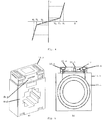
- the Fig. 1 shows a first exemplary embodiment of the protective circuit 12 according to the invention for a current transformer 10.
- the protective circuit 12 serves to prevent a secondary voltage Us on a secondary circuit 10.1 of the current transformer 10 from exceeding a secondary voltage threshold value.
- the control unit 16 is designed to provide a control signal to the switch unit 18 in response to the secondary voltage Us exceeding the secondary voltage threshold value.
- the switch unit 18 is designed to respond to that provided by the control unit 16 Control signal to short-circuit the protective circuit input 12.1.
- Fig. 1 is also a current measuring device 20, which is designed to measure the current through the secondary circuit 10.1.
- An overvoltage in the secondary circuit 10.1 is very unlikely to occur during measurement operation. However, the probability of an overvoltage or excessive secondary voltage Us occurring increases substantially as soon as the ammeter 20 is disconnected from the secondary circuit 10.1, which is shown in FIG Fig. 1 is indicated.
- the control unit 16 When an excessive secondary voltage Us occurs on the secondary circuit 10.1, a voltage is applied to the control unit 16 which exceeds a preset secondary voltage threshold value. In response to this exceedance, the control unit 16 provides a control signal to the switch unit 18, which, for example, changes from LOW to HIGH. In response to the control signal, the switching unit 18 reduces its internal resistance to approximately zero and thus short-circuits the secondary circuit 10.1.
- FIG. 10 shows a second exemplary embodiment of the protective circuit 12 according to the invention for a current transformer 10.
- the protective circuit 12 according to the FIG Fig. 2 embodiment shown a limiting unit 14, the is connected in parallel to the control unit 16 and to the switch unit 18 and is connected to the secondary circuit 10.1.
- Limiting unit 14, switch unit 18 and control unit 16 advantageously complement and support one another with regard to the protective function for current transformer 12.
- switch unit 18 is designed for higher currents than limiting unit 14.
- the components switch unit 18 and limiting unit 14 can withstand a greater current than each component on its own.
- the limiting unit 14 supports the control unit 16 because a defined voltage is provided at the input of the control unit 16 by means of the parallel connection of the limiting unit 14 and the control unit 16.
- suppressor diodes which are preferably used for the limiting unit 14, have after reaching the breakdown voltage (see Fig. 4 ) still have a finite internal resistance, so that they can only carry continuous currents that are lower than the usual secondary rated currents of converters. This is one possible reason why no protective circuits are known that consist solely of suppressor diodes.
- the short time required to short-circuit the switch unit 18 ensures a negligibly small inertia of the protective circuit 12, since the control unit 16 "scans" every half-wave of the voltage on the secondary circuit 10.1. can. As soon as the voltage has fallen again below a predetermined limit value, the short-circuit on the secondary side caused by the protective circuit 12 is automatically canceled within a very short time. The activation takes place periodically.
- the switch unit 18 comprises two MOSFETs T1, T2 arranged in a back-to-back circuit.
- the drain connections of the transistors T1, T2 are each connected to the terminals of the protective circuit input, and the gates are connected to the comparator K of the comparator unit 16.2 for supplying the control signal.
- a short circuit is advantageously established automatically with the small and light semiconductors of the two N-channel FETs that are arranged in the back-to-back circuit.
- the two transistors T1, T2 short-circuit the alternating current through the secondary circuit 10.1 with almost no power. This makes it possible to discharge very high currents, such as a thermal rated short-time current, which is 60 times the rated current of 5A, i.e. 300 A, for one second and a rated surge current which is 2.5 times the Rated short-term current, i.e. 750 A, is to be derived for a half-wave.
- very high currents such as a thermal rated short-time current, which is 60 times the rated current of 5A, i.e. 300 A, for one second and a rated surge current which is 2.5 times the Rated short-term current, i.e. 750 A, is to be derived for a half-wave.
- the short circuit is carried out before the voltage exceeds a dangerous level.
- a dangerous level corresponds to a quotient of the rated power and the secondary rated current of the measuring transformer.
- the rectified voltage Ug is determined by the comparator K, with the voltage on a Zener diode D2 compared.
- the current through the rectifier 22 charges the capacitor C, which provides the necessary voltage for the comparator K and the control of the transistors T1, T2.
- the secondary circuit 10.1 As soon as the voltage at the input of the comparator K reaches the threshold voltage of the comparator K, the secondary circuit 10.1 is short-circuited and the capacitor C discharges via R1, R2, R3, D1 and K until the cut-off voltage at the positive input of the comparator K is reached again.
- a secondary voltage threshold value results that is twice the level of the Zener voltage.
- the operating voltage of the comparator K is separated from the short circuit by the rectifier diodes. If, after the short circuit has been removed, the secondary circuit 10.1 is still too high in voltage, the process is repeated so that the switch-on voltage at the positive input of the comparator K can never be exceeded.
- the switch-on voltage and switch-off voltage at the positive input of the comparator K are separated via R4 by a hysteresis of the comparator unit 16.2, so that none undefined vibrations can arise.
- the switching thresholds are determined by the Zener diode D2 and the set hysteresis.
- the ratio of the resistors R2, R3 to the capacitor C determines the frequency of the switching process.
- This protective circuit 12 can be accommodated in the head of the current transformer 10 and firmly connected to the secondary circuit 10.1. Thus, the automatic short circuit always works, regardless of where the secondary circuit 10.1 is interrupted.
- a connection cable to the protective circuit 12 can be interrupted at any point between the current transformer 10 and the measuring device 20, directly or immediately at the connections of the current transformer 10 or of the measuring device 20.
- the protective circuit 12 can also be inserted into the secondary circuit after the current transformer 10 has been completed. This means that the current transformer 10 can be retrofitted with the protective circuit 12.
- One possibility for reducing costs and size is to limit the maximum current of the secondary circuit 10.1 by varying the material of the current transformer 10.
- the magnetic flux can be limited by adapted core material, which also limits the current in the secondary circuit 10.1.
- the protective circuit 12 is housed or arranged in the current transformer housing 10.2, preferably in the secondary terminal box 10.3.
- the protective circuit 12 is arranged directly or immediately at the secondary terminals of the secondary circuit 10.1.
- the protective circuit is thus completely integrated in the housing 10.2 of the current transformer 10.
Landscapes
- Engineering & Computer Science (AREA)
- Power Engineering (AREA)
- Physics & Mathematics (AREA)
- General Physics & Mathematics (AREA)
- Emergency Protection Circuit Devices (AREA)
- Dc-Dc Converters (AREA)
- Protection Of Static Devices (AREA)
Claims (7)
- Circuit de protection pour transformateur de courant (10), destiné à empêcher qu'une tension secondaire (Us) sur un circuit secondaire (10.1) du transformateur de courant (10) ne dépasse une valeur seuil de tension secondaire, comprenant- une entrée de circuit de protection (12.1) qui peut être couplée au circuit secondaire (10.1) du transformateur de courant (10), de manière à ce que la tension secondaire (Us) soit appliquée à l'entrée de circuit de protection (12.1),- une unité de commande (16) reliée à l'entrée de circuit de protection (12.1), et- une unité d'interrupteur (18) qui est reliée à l'entrée de circuit de protection (12.1) et est reliée avec possibilité d'activation à l'unité de commande (16),dans lequel- l'unité de commande (16) comprend une unité de comparateur (16.2) et est conçue pour réagir au dépassement de la valeur seuil de tension secondaire par la tension secondaire (Us) et fournir un signal de commande à l'unité d'interrupteur (18), si une tension d'entrée de l'unité de comparateur (16.2) dépasse une valeur seuil,- l'unité de commande (16) comprend en outre un redresseur (16.1) qui est relié à l'entrée de circuit de protection (12.1) et est destiné à fournir une tension continue (Ug) dépendant d'une amplitude de la tension secondaire (Us), en tant que tension d'entrée de l'unité de comparateur (16.2),- l'unité d'interrupteur (18) est réalisée sous forme de circuit à semi-conducteur comprenant deux MOSFETs (T1, T2) qui sont disposés dans un montage tête-bêche, dans une configuration anti-série, et sont reliés l'un à l'autre par une borne centrale,- le redresseur (16.1) comporte quatre branches de pont, où deux branches de pont fournissent la tension continue (Ug) et deux branches de pont sont reliées à la borne centrale de l'unité d'interrupteur, et- l'unité d'interrupteur (18) est agencée pour réagir au signal de commande fourni par l'unité de commande (16) et mettre en court-circuit l'entrée de circuit de protection (12.1).
- Circuit de protection selon la revendication 1, caractérisé en ce qu'il présente au moins l'une des caractéristiques suivantes :- l'unité de commande (16) est reliée directement ou indirectement à l'entrée de circuit de protection (12.1) ;- l'unité d'interrupteur (18) est reliée directement ou indirectement à l'entrée de circuit de protection (12.1) ;- le circuit de protection (12) comprend une unité de limitation (14) pour une protection contre les surtensions, qui est reliée à l'entrée de circuit de protection (12.1).
- Circuit de protection selon l'une des revendications précédentes, caractérisé en ce que l'unité de comparateur (16.2) comprend un ou plusieurs des composants suivants :- un comparateur (K) avec une entrée positive, une entrée négative, à laquelle est appliquée une tension d'une valeur correspondant approximativement à la tension d'entrée de l'unité de comparateur (16.2), et une sortie qui fournit le signal de commande ;- un diviseur de tension (R2, R3), l'entrée positive étant connectée à la tension d'entrée de l'unité de comparateur (16.2) par l'intermédiaire du diviseur de tension (R2, R3) ;- une diode Zener (D2) qui est reliée à l'entrée négative, en vue de la limitation d'une tension appliquée à l'entrée négative ;- un condensateur (C) qui est relié à l'entrée positive.
- Circuit de protection selon l'une des revendications précédentes, caractérisé en ce que l'unité d'interrupteur (18) comprend un coupleur optoélectronique destiné à coupler le signal de commande.
- Circuit de protection selon l'une des revendications précédentes, caractérisé en ce que l'unité de limitation (14) comprend un ou plusieurs des composants suivants :- une diode de suppression (D1) ;- un varistor ;- un élément d'évacuation de gaz.
- Transformateur de courant doté d'un circuit de protection (12) selon l'une des revendications précédentes.
- Transformateur de courant selon la revendication précédente, caractérisé en ce que le circuit de protection (12) est logé dans le boîtier (10.2), en particulier dans la boîte de bornes secondaires (10.3) du transformateur de courant (10).
Applications Claiming Priority (2)
| Application Number | Priority Date | Filing Date | Title |
|---|---|---|---|
| DE102012111061.1A DE102012111061A1 (de) | 2012-11-16 | 2012-11-16 | Schutzschaltung für einen Stromwandler und Stromwandler mit einer Schutzschaltung |
| PCT/EP2013/073305 WO2014075989A1 (fr) | 2012-11-16 | 2013-11-07 | Circuit de protection pour transformateur de courant et transformateur de courant comprenant un circuit de protection |
Publications (2)
| Publication Number | Publication Date |
|---|---|
| EP2920857A1 EP2920857A1 (fr) | 2015-09-23 |
| EP2920857B1 true EP2920857B1 (fr) | 2021-07-28 |
Family
ID=49554252
Family Applications (1)
| Application Number | Title | Priority Date | Filing Date |
|---|---|---|---|
| EP13789278.2A Active EP2920857B1 (fr) | 2012-11-16 | 2013-11-07 | Circuit de protection pour transformateur de courant et transformateur de courant comprenant un circuit de protection |
Country Status (5)
| Country | Link |
|---|---|
| US (1) | US10498138B2 (fr) |
| EP (1) | EP2920857B1 (fr) |
| CN (2) | CN111864712B (fr) |
| DE (1) | DE102012111061A1 (fr) |
| WO (1) | WO2014075989A1 (fr) |
Families Citing this family (18)
| Publication number | Priority date | Publication date | Assignee | Title |
|---|---|---|---|---|
| DE102014105888A1 (de) * | 2014-04-25 | 2015-10-29 | Phoenix Contact Gmbh & Co. Kg | Andockmodul für einen Stromwandler und Stromwandler mit einem Andockmodul |
| US9489026B2 (en) * | 2014-11-13 | 2016-11-08 | Electronic Systems Protection, Inc. | Selective event reaction processing in power control |
| US10014680B2 (en) * | 2014-12-09 | 2018-07-03 | Electronic Systems Protection, Inc. | Overvoltage notching of electricity delivered to an electrical load |
| WO2016125028A2 (fr) * | 2015-02-03 | 2016-08-11 | Abb Technology Ltd. | Système de surveillance de ligne de transport d'énergie électrique |
| DE102015103296B4 (de) * | 2015-03-06 | 2022-06-09 | Phoenix Contact Gmbh & Co. Kg | Messvorrichtung zum Bereitstellen eines normierten elektrischen Ausgangssignals und elektronischer Messumformer |
| DE102015115410A1 (de) * | 2015-09-11 | 2017-03-16 | Phoenix Contact Gmbh & Co. Kg | Induktive Strommesswandlervorrichtung |
| FR3047084B1 (fr) * | 2016-01-22 | 2018-02-16 | Safran Electrical & Power | Dispositif de mesure du courant protege contre les surtensions en cas d'ouverture du circuit |
| DE102017109378B4 (de) * | 2017-02-16 | 2022-07-07 | Dehn Se | Elektronische Sicherung für eine, an ein Niedervolt-Gleichspannungsnetz anschließbare Last zum Schutz vor transienten und temporären Überspannungen |
| IL264042B (en) | 2018-12-31 | 2020-07-30 | Doron Eyal | Systems and methods for regulating force withdrawal from inspiratory force |
| CN111537907A (zh) * | 2020-05-15 | 2020-08-14 | 北京小米移动软件有限公司 | 电源通断检测电路、方法、装置及存储介质 |
| CN112129985B (zh) * | 2020-09-09 | 2023-12-22 | 贵州电网有限责任公司 | 一种钳式互感器智能控制装置 |
| CN113064062A (zh) * | 2021-03-26 | 2021-07-02 | 广东电网有限责任公司 | 断路器二次回路的监测电路和装置 |
| JP2022177896A (ja) * | 2021-05-19 | 2022-12-02 | 株式会社ノーリツ | 浴槽洗浄コントローラ |
| CN113937725B (zh) * | 2021-09-07 | 2025-02-07 | 华为数字能源技术有限公司 | 短路保护装置、目标电路的短路保护方法及功率变换设备 |
| GB2614280B (en) * | 2021-12-23 | 2024-06-05 | Synaptec Ltd | Signal conditioning stage |
| EP4213327A1 (fr) | 2022-01-14 | 2023-07-19 | ADB Safegate BV | Dispositif de limitation de tension pour circuits à courant constant |
| EP4470080A1 (fr) * | 2022-01-24 | 2024-12-04 | Micro Motion, Inc. | Circuit de protection contre les anomalies sur temporisateur |
| CN120319593B (zh) * | 2025-06-16 | 2025-09-19 | 山东元星电子有限公司 | 一种带开路保护功能的电流互感器及其保护方法 |
Citations (5)
| Publication number | Priority date | Publication date | Assignee | Title |
|---|---|---|---|---|
| US3030524A (en) * | 1958-12-17 | 1962-04-17 | Bell Telephone Labor Inc | Balanced transistor swiching circuits |
| US5103154A (en) * | 1990-05-25 | 1992-04-07 | Texas Instruments Incorporated | Start winding switch protection circuit |
| WO2004040761A1 (fr) * | 2002-10-29 | 2004-05-13 | Koninklijke Philips Electronics N.V. | Commutateur a deux transistors nmos bidirectionnel |
| DE102007008264A1 (de) * | 2007-02-20 | 2008-08-21 | Robert Bosch Gmbh | Schaltungsanordnung mit einem bidirektional sperrenden Halbleiterrelais |
| US20100270982A1 (en) * | 2009-04-24 | 2010-10-28 | Lutron Electronics Co., Inc. | Smart Electronic Switch for Low-Power Loads |
Family Cites Families (22)
| Publication number | Priority date | Publication date | Assignee | Title |
|---|---|---|---|---|
| BE559161A (fr) | 1956-07-18 | |||
| CA1152556A (fr) * | 1981-03-03 | 1983-08-23 | Julien Simard | Protecteur de transformateur d'intensite |
| US4698740A (en) * | 1986-02-14 | 1987-10-06 | Westinghouse Electric Corp. | Current fed regulated voltage supply |
| FR2664760B1 (fr) * | 1990-07-13 | 1996-09-27 | Sgs Thomson Microelectronics | Dispositif de protection contre des surtensions et sa realisation monolithique. |
| US5488534A (en) * | 1993-08-19 | 1996-01-30 | Emerson Electric Co. | Transient voltage surge suppression module with ultrafast fusing |
| JPH08317561A (ja) * | 1995-05-22 | 1996-11-29 | Tokyo Electric Power Co Inc:The | 高調波抑制装置 |
| CA2183176C (fr) * | 1995-08-18 | 2000-10-24 | Brian R. Pelly | Dispositif de blocage de courant continu grande puissance pour la mise a la terre de courant alternatif et de defaut |
| DE69605530T2 (de) * | 1995-09-25 | 2000-07-20 | Koninklijke Philips Electronics N.V., Eindhoven | Leistungsversorgungsschaltung mit einem transformator und einem schalter auf der sekundärseite des transformators |
| DE19641187C2 (de) * | 1996-09-24 | 1998-07-23 | Siemens Ag | Schaltungsanordnung zur Energieversorgung von elektronischen Auslöseeinrichtungen |
| FR2764136B1 (fr) * | 1997-05-28 | 1999-08-13 | Sgs Thomson Microelectronics | Protection contre des surtensions d'un transistor mos de puissance integre |
| CN1190876C (zh) * | 2000-07-18 | 2005-02-23 | 全汉企业股份有限公司 | 电源供应器的过电压保护电路 |
| EP1304786A1 (fr) * | 2001-10-18 | 2003-04-23 | ABB Schweiz AG | Limiteur de tension |
| US7102253B2 (en) * | 2001-12-31 | 2006-09-05 | Lewis James M | MOSFET based, high voltage, electronic relays for AC power switching and inductive loads |
| JP3656911B2 (ja) * | 2002-09-27 | 2005-06-08 | オリオン電機株式会社 | 電源回路 |
| CN201528192U (zh) * | 2009-10-23 | 2010-07-14 | 佛山市南海展晴玩具有限公司 | 霓虹灯电子变压器保护电路 |
| CN101854766B (zh) * | 2010-04-23 | 2013-03-27 | 清华大学 | 无极灯电源电路,及其保护方法和保护电路 |
| US8861164B2 (en) * | 2011-02-04 | 2014-10-14 | Fairchild Semiconductor Corporation | Integrated overdrive and overvoltage protection device |
| US20120243136A1 (en) * | 2011-03-23 | 2012-09-27 | Satcon Technology Corporation | Surge protection arrangement for electrical circuits |
| US8929042B2 (en) * | 2011-03-30 | 2015-01-06 | Thomas & Betts International, Inc. | Surge protective device with contoller |
| US9066453B2 (en) * | 2012-03-06 | 2015-06-23 | Mission Motor Company | Power electronic system and method of assembly |
| CN102709901B (zh) * | 2012-06-14 | 2016-06-01 | 北京恒源利通电力技术有限公司 | 电流互感器过压保护方法和装置 |
| CN103683523B (zh) * | 2012-09-07 | 2018-04-13 | 捷通国际有限公司 | 用于双向无线功率传输的系统和方法 |
-
2012
- 2012-11-16 DE DE102012111061.1A patent/DE102012111061A1/de not_active Withdrawn
-
2013
- 2013-11-07 US US14/442,886 patent/US10498138B2/en active Active
- 2013-11-07 EP EP13789278.2A patent/EP2920857B1/fr active Active
- 2013-11-07 CN CN202010741426.8A patent/CN111864712B/zh active Active
- 2013-11-07 CN CN201380065720.XA patent/CN105191043A/zh active Pending
- 2013-11-07 WO PCT/EP2013/073305 patent/WO2014075989A1/fr not_active Ceased
Patent Citations (5)
| Publication number | Priority date | Publication date | Assignee | Title |
|---|---|---|---|---|
| US3030524A (en) * | 1958-12-17 | 1962-04-17 | Bell Telephone Labor Inc | Balanced transistor swiching circuits |
| US5103154A (en) * | 1990-05-25 | 1992-04-07 | Texas Instruments Incorporated | Start winding switch protection circuit |
| WO2004040761A1 (fr) * | 2002-10-29 | 2004-05-13 | Koninklijke Philips Electronics N.V. | Commutateur a deux transistors nmos bidirectionnel |
| DE102007008264A1 (de) * | 2007-02-20 | 2008-08-21 | Robert Bosch Gmbh | Schaltungsanordnung mit einem bidirektional sperrenden Halbleiterrelais |
| US20100270982A1 (en) * | 2009-04-24 | 2010-10-28 | Lutron Electronics Co., Inc. | Smart Electronic Switch for Low-Power Loads |
Also Published As
| Publication number | Publication date |
|---|---|
| CN111864712A (zh) | 2020-10-30 |
| DE102012111061A1 (de) | 2014-05-22 |
| US10498138B2 (en) | 2019-12-03 |
| EP2920857A1 (fr) | 2015-09-23 |
| CN111864712B (zh) | 2023-07-14 |
| WO2014075989A1 (fr) | 2014-05-22 |
| CN105191043A (zh) | 2015-12-23 |
| US20150333509A1 (en) | 2015-11-19 |
Similar Documents
| Publication | Publication Date | Title |
|---|---|---|
| EP2920857B1 (fr) | Circuit de protection pour transformateur de courant et transformateur de courant comprenant un circuit de protection | |
| DE102014105888A1 (de) | Andockmodul für einen Stromwandler und Stromwandler mit einem Andockmodul | |
| EP2418748B1 (fr) | Dispositif d'alimentation en énergie | |
| EP0890220B1 (fr) | Appareil de commutation electronique de derivation | |
| DE3622293A1 (de) | Festkoerper-nebenschlussschaltkreis fuer leckstromleistungssteuerung | |
| WO2011036287A1 (fr) | Procédé de mise en court-circuit | |
| BE1026372B1 (de) | Schutzvorrichtung | |
| WO2010046247A1 (fr) | Circuit de protection et appareil de mesure doté d'un tel circuit de protection | |
| DE102011011983A1 (de) | Fehlerstrom-Schutzeinrichtung | |
| EP0295415A2 (fr) | Circuit de protection contre les courants de défaut | |
| EP1078432B1 (fr) | Disjoncteur de protection | |
| DE3531023A1 (de) | Schaltungsanordnung zur erfassung eines fehler- bzw. differenzstromes | |
| WO2023011768A1 (fr) | Unité de disjoncteur | |
| DE102018112914B4 (de) | Elektrische Schutzvorrichtung für eine mechanische Anlage | |
| DE3814251C1 (en) | Protective circuit for capacitive loads | |
| EP2355287A1 (fr) | Dispositif de protection contre les surtensions pour moteurs électriques | |
| EP3053270B1 (fr) | Circuit inverseur à limitation de tension | |
| DE102020206253B3 (de) | Überspannungsschutz | |
| EP2394150A1 (fr) | Capteur de température à semiconducteur avec protection contre les décharges électrostatiques | |
| DE102018114129A1 (de) | Schutzvorrichtung | |
| DE102012222782A1 (de) | Schaltvorrichtung mit Überspannungsschutz | |
| DE102010061766A1 (de) | Schalter, insbesondere Leistungsschalter für Niederspannungen | |
| WO2008141595A1 (fr) | Câblage de sécurité | |
| DE102018212950B4 (de) | Niederspannungsleistungsschalter und Verfahren | |
| DE60112321T2 (de) | Einer messschnittstelle zuordbare einrichtung zur unterdrückung von störungen |
Legal Events
| Date | Code | Title | Description |
|---|---|---|---|
| PUAI | Public reference made under article 153(3) epc to a published international application that has entered the european phase |
Free format text: ORIGINAL CODE: 0009012 |
|
| 17P | Request for examination filed |
Effective date: 20150414 |
|
| AK | Designated contracting states |
Kind code of ref document: A1 Designated state(s): AL AT BE BG CH CY CZ DE DK EE ES FI FR GB GR HR HU IE IS IT LI LT LU LV MC MK MT NL NO PL PT RO RS SE SI SK SM TR |
|
| AX | Request for extension of the european patent |
Extension state: BA ME |
|
| DAX | Request for extension of the european patent (deleted) | ||
| STAA | Information on the status of an ep patent application or granted ep patent |
Free format text: STATUS: EXAMINATION IS IN PROGRESS |
|
| 17Q | First examination report despatched |
Effective date: 20180801 |
|
| REG | Reference to a national code |
Ref country code: DE Ref legal event code: R079 Ref document number: 502013015854 Country of ref document: DE Free format text: PREVIOUS MAIN CLASS: H02H0009040000 Ipc: H03K0017687000 |
|
| GRAP | Despatch of communication of intention to grant a patent |
Free format text: ORIGINAL CODE: EPIDOSNIGR1 |
|
| STAA | Information on the status of an ep patent application or granted ep patent |
Free format text: STATUS: GRANT OF PATENT IS INTENDED |
|
| RIC1 | Information provided on ipc code assigned before grant |
Ipc: H03K 17/687 20060101AFI20210325BHEP Ipc: H02H 9/04 20060101ALI20210325BHEP Ipc: H01F 27/40 20060101ALI20210325BHEP Ipc: G01R 1/36 20060101ALI20210325BHEP Ipc: G01R 15/18 20060101ALI20210325BHEP Ipc: H01F 38/32 20060101ALI20210325BHEP Ipc: H02H 7/04 20060101ALI20210325BHEP Ipc: H03K 17/082 20060101ALI20210325BHEP |
|
| INTG | Intention to grant announced |
Effective date: 20210420 |
|
| GRAS | Grant fee paid |
Free format text: ORIGINAL CODE: EPIDOSNIGR3 |
|
| GRAA | (expected) grant |
Free format text: ORIGINAL CODE: 0009210 |
|
| STAA | Information on the status of an ep patent application or granted ep patent |
Free format text: STATUS: THE PATENT HAS BEEN GRANTED |
|
| AK | Designated contracting states |
Kind code of ref document: B1 Designated state(s): AL AT BE BG CH CY CZ DE DK EE ES FI FR GB GR HR HU IE IS IT LI LT LU LV MC MK MT NL NO PL PT RO RS SE SI SK SM TR |
|
| REG | Reference to a national code |
Ref country code: GB Ref legal event code: FG4D Free format text: NOT ENGLISH |
|
| REG | Reference to a national code |
Ref country code: CH Ref legal event code: EP |
|
| REG | Reference to a national code |
Ref country code: DE Ref legal event code: R096 Ref document number: 502013015854 Country of ref document: DE |
|
| REG | Reference to a national code |
Ref country code: AT Ref legal event code: REF Ref document number: 1415639 Country of ref document: AT Kind code of ref document: T Effective date: 20210815 |
|
| REG | Reference to a national code |
Ref country code: IE Ref legal event code: FG4D Free format text: LANGUAGE OF EP DOCUMENT: GERMAN |
|
| REG | Reference to a national code |
Ref country code: LT Ref legal event code: MG9D |
|
| REG | Reference to a national code |
Ref country code: NL Ref legal event code: MP Effective date: 20210728 |
|
| PG25 | Lapsed in a contracting state [announced via postgrant information from national office to epo] |
Ref country code: NO Free format text: LAPSE BECAUSE OF FAILURE TO SUBMIT A TRANSLATION OF THE DESCRIPTION OR TO PAY THE FEE WITHIN THE PRESCRIBED TIME-LIMIT Effective date: 20211028 Ref country code: PT Free format text: LAPSE BECAUSE OF FAILURE TO SUBMIT A TRANSLATION OF THE DESCRIPTION OR TO PAY THE FEE WITHIN THE PRESCRIBED TIME-LIMIT Effective date: 20211129 Ref country code: RS Free format text: LAPSE BECAUSE OF FAILURE TO SUBMIT A TRANSLATION OF THE DESCRIPTION OR TO PAY THE FEE WITHIN THE PRESCRIBED TIME-LIMIT Effective date: 20210728 Ref country code: NL Free format text: LAPSE BECAUSE OF FAILURE TO SUBMIT A TRANSLATION OF THE DESCRIPTION OR TO PAY THE FEE WITHIN THE PRESCRIBED TIME-LIMIT Effective date: 20210728 Ref country code: ES Free format text: LAPSE BECAUSE OF FAILURE TO SUBMIT A TRANSLATION OF THE DESCRIPTION OR TO PAY THE FEE WITHIN THE PRESCRIBED TIME-LIMIT Effective date: 20210728 Ref country code: FI Free format text: LAPSE BECAUSE OF FAILURE TO SUBMIT A TRANSLATION OF THE DESCRIPTION OR TO PAY THE FEE WITHIN THE PRESCRIBED TIME-LIMIT Effective date: 20210728 Ref country code: LT Free format text: LAPSE BECAUSE OF FAILURE TO SUBMIT A TRANSLATION OF THE DESCRIPTION OR TO PAY THE FEE WITHIN THE PRESCRIBED TIME-LIMIT Effective date: 20210728 Ref country code: BG Free format text: LAPSE BECAUSE OF FAILURE TO SUBMIT A TRANSLATION OF THE DESCRIPTION OR TO PAY THE FEE WITHIN THE PRESCRIBED TIME-LIMIT Effective date: 20211028 Ref country code: HR Free format text: LAPSE BECAUSE OF FAILURE TO SUBMIT A TRANSLATION OF THE DESCRIPTION OR TO PAY THE FEE WITHIN THE PRESCRIBED TIME-LIMIT Effective date: 20210728 Ref country code: SE Free format text: LAPSE BECAUSE OF FAILURE TO SUBMIT A TRANSLATION OF THE DESCRIPTION OR TO PAY THE FEE WITHIN THE PRESCRIBED TIME-LIMIT Effective date: 20210728 |
|
| PG25 | Lapsed in a contracting state [announced via postgrant information from national office to epo] |
Ref country code: PL Free format text: LAPSE BECAUSE OF FAILURE TO SUBMIT A TRANSLATION OF THE DESCRIPTION OR TO PAY THE FEE WITHIN THE PRESCRIBED TIME-LIMIT Effective date: 20210728 Ref country code: LV Free format text: LAPSE BECAUSE OF FAILURE TO SUBMIT A TRANSLATION OF THE DESCRIPTION OR TO PAY THE FEE WITHIN THE PRESCRIBED TIME-LIMIT Effective date: 20210728 Ref country code: GR Free format text: LAPSE BECAUSE OF FAILURE TO SUBMIT A TRANSLATION OF THE DESCRIPTION OR TO PAY THE FEE WITHIN THE PRESCRIBED TIME-LIMIT Effective date: 20211029 |
|
| PG25 | Lapsed in a contracting state [announced via postgrant information from national office to epo] |
Ref country code: DK Free format text: LAPSE BECAUSE OF FAILURE TO SUBMIT A TRANSLATION OF THE DESCRIPTION OR TO PAY THE FEE WITHIN THE PRESCRIBED TIME-LIMIT Effective date: 20210728 |
|
| REG | Reference to a national code |
Ref country code: DE Ref legal event code: R097 Ref document number: 502013015854 Country of ref document: DE |
|
| PG25 | Lapsed in a contracting state [announced via postgrant information from national office to epo] |
Ref country code: SM Free format text: LAPSE BECAUSE OF FAILURE TO SUBMIT A TRANSLATION OF THE DESCRIPTION OR TO PAY THE FEE WITHIN THE PRESCRIBED TIME-LIMIT Effective date: 20210728 Ref country code: SK Free format text: LAPSE BECAUSE OF FAILURE TO SUBMIT A TRANSLATION OF THE DESCRIPTION OR TO PAY THE FEE WITHIN THE PRESCRIBED TIME-LIMIT Effective date: 20210728 Ref country code: RO Free format text: LAPSE BECAUSE OF FAILURE TO SUBMIT A TRANSLATION OF THE DESCRIPTION OR TO PAY THE FEE WITHIN THE PRESCRIBED TIME-LIMIT Effective date: 20210728 Ref country code: EE Free format text: LAPSE BECAUSE OF FAILURE TO SUBMIT A TRANSLATION OF THE DESCRIPTION OR TO PAY THE FEE WITHIN THE PRESCRIBED TIME-LIMIT Effective date: 20210728 Ref country code: CZ Free format text: LAPSE BECAUSE OF FAILURE TO SUBMIT A TRANSLATION OF THE DESCRIPTION OR TO PAY THE FEE WITHIN THE PRESCRIBED TIME-LIMIT Effective date: 20210728 Ref country code: AL Free format text: LAPSE BECAUSE OF FAILURE TO SUBMIT A TRANSLATION OF THE DESCRIPTION OR TO PAY THE FEE WITHIN THE PRESCRIBED TIME-LIMIT Effective date: 20210728 |
|
| PLBE | No opposition filed within time limit |
Free format text: ORIGINAL CODE: 0009261 |
|
| STAA | Information on the status of an ep patent application or granted ep patent |
Free format text: STATUS: NO OPPOSITION FILED WITHIN TIME LIMIT |
|
| PG25 | Lapsed in a contracting state [announced via postgrant information from national office to epo] |
Ref country code: MC Free format text: LAPSE BECAUSE OF FAILURE TO SUBMIT A TRANSLATION OF THE DESCRIPTION OR TO PAY THE FEE WITHIN THE PRESCRIBED TIME-LIMIT Effective date: 20210728 |
|
| REG | Reference to a national code |
Ref country code: CH Ref legal event code: PL |
|
| 26N | No opposition filed |
Effective date: 20220429 |
|
| GBPC | Gb: european patent ceased through non-payment of renewal fee |
Effective date: 20211107 |
|
| PG25 | Lapsed in a contracting state [announced via postgrant information from national office to epo] |
Ref country code: LU Free format text: LAPSE BECAUSE OF NON-PAYMENT OF DUE FEES Effective date: 20211107 Ref country code: IT Free format text: LAPSE BECAUSE OF FAILURE TO SUBMIT A TRANSLATION OF THE DESCRIPTION OR TO PAY THE FEE WITHIN THE PRESCRIBED TIME-LIMIT Effective date: 20210728 Ref country code: BE Free format text: LAPSE BECAUSE OF NON-PAYMENT OF DUE FEES Effective date: 20211130 |
|
| REG | Reference to a national code |
Ref country code: BE Ref legal event code: MM Effective date: 20211130 |
|
| PG25 | Lapsed in a contracting state [announced via postgrant information from national office to epo] |
Ref country code: LI Free format text: LAPSE BECAUSE OF NON-PAYMENT OF DUE FEES Effective date: 20211130 Ref country code: CH Free format text: LAPSE BECAUSE OF NON-PAYMENT OF DUE FEES Effective date: 20211130 |
|
| PG25 | Lapsed in a contracting state [announced via postgrant information from national office to epo] |
Ref country code: IE Free format text: LAPSE BECAUSE OF NON-PAYMENT OF DUE FEES Effective date: 20211107 Ref country code: GB Free format text: LAPSE BECAUSE OF NON-PAYMENT OF DUE FEES Effective date: 20211107 |
|
| PG25 | Lapsed in a contracting state [announced via postgrant information from national office to epo] |
Ref country code: FR Free format text: LAPSE BECAUSE OF NON-PAYMENT OF DUE FEES Effective date: 20211130 |
|
| REG | Reference to a national code |
Ref country code: AT Ref legal event code: MM01 Ref document number: 1415639 Country of ref document: AT Kind code of ref document: T Effective date: 20211107 |
|
| PG25 | Lapsed in a contracting state [announced via postgrant information from national office to epo] |
Ref country code: AT Free format text: LAPSE BECAUSE OF NON-PAYMENT OF DUE FEES Effective date: 20211107 |
|
| PG25 | Lapsed in a contracting state [announced via postgrant information from national office to epo] |
Ref country code: HU Free format text: LAPSE BECAUSE OF FAILURE TO SUBMIT A TRANSLATION OF THE DESCRIPTION OR TO PAY THE FEE WITHIN THE PRESCRIBED TIME-LIMIT; INVALID AB INITIO Effective date: 20131107 |
|
| P01 | Opt-out of the competence of the unified patent court (upc) registered |
Effective date: 20230424 |
|
| PG25 | Lapsed in a contracting state [announced via postgrant information from national office to epo] |
Ref country code: CY Free format text: LAPSE BECAUSE OF FAILURE TO SUBMIT A TRANSLATION OF THE DESCRIPTION OR TO PAY THE FEE WITHIN THE PRESCRIBED TIME-LIMIT Effective date: 20210728 |
|
| PG25 | Lapsed in a contracting state [announced via postgrant information from national office to epo] |
Ref country code: MK Free format text: LAPSE BECAUSE OF FAILURE TO SUBMIT A TRANSLATION OF THE DESCRIPTION OR TO PAY THE FEE WITHIN THE PRESCRIBED TIME-LIMIT Effective date: 20210728 |
|
| PG25 | Lapsed in a contracting state [announced via postgrant information from national office to epo] |
Ref country code: TR Free format text: LAPSE BECAUSE OF FAILURE TO SUBMIT A TRANSLATION OF THE DESCRIPTION OR TO PAY THE FEE WITHIN THE PRESCRIBED TIME-LIMIT Effective date: 20210728 |
|
| PG25 | Lapsed in a contracting state [announced via postgrant information from national office to epo] |
Ref country code: MT Free format text: LAPSE BECAUSE OF FAILURE TO SUBMIT A TRANSLATION OF THE DESCRIPTION OR TO PAY THE FEE WITHIN THE PRESCRIBED TIME-LIMIT Effective date: 20210728 |
|
| PGFP | Annual fee paid to national office [announced via postgrant information from national office to epo] |
Ref country code: DE Payment date: 20241231 Year of fee payment: 12 |