EP2921035B1 - Système de réflecteur - Google Patents
Système de réflecteur Download PDFInfo
- Publication number
- EP2921035B1 EP2921035B1 EP13753605.8A EP13753605A EP2921035B1 EP 2921035 B1 EP2921035 B1 EP 2921035B1 EP 13753605 A EP13753605 A EP 13753605A EP 2921035 B1 EP2921035 B1 EP 2921035B1
- Authority
- EP
- European Patent Office
- Prior art keywords
- reflector
- fixing
- circuit board
- fixing element
- led circuit
- Prior art date
- Legal status (The legal status is an assumption and is not a legal conclusion. Google has not performed a legal analysis and makes no representation as to the accuracy of the status listed.)
- Not-in-force
Links
Images


Classifications
-
- H—ELECTRICITY
- H05—ELECTRIC TECHNIQUES NOT OTHERWISE PROVIDED FOR
- H05K—PRINTED CIRCUITS; CASINGS OR CONSTRUCTIONAL DETAILS OF ELECTRIC APPARATUS; MANUFACTURE OF ASSEMBLAGES OF ELECTRICAL COMPONENTS
- H05K1/00—Printed circuits
- H05K1/02—Details
- H05K1/0274—Optical details, e.g. printed circuits comprising integral optical means
-
- F—MECHANICAL ENGINEERING; LIGHTING; HEATING; WEAPONS; BLASTING
- F21—LIGHTING
- F21V—FUNCTIONAL FEATURES OR DETAILS OF LIGHTING DEVICES OR SYSTEMS THEREOF; STRUCTURAL COMBINATIONS OF LIGHTING DEVICES WITH OTHER ARTICLES, NOT OTHERWISE PROVIDED FOR
- F21V17/00—Fastening of component parts of lighting devices, e.g. shades, globes, refractors, reflectors, filters, screens, grids or protective cages
- F21V17/005—Fastening of component parts of lighting devices, e.g. shades, globes, refractors, reflectors, filters, screens, grids or protective cages with keying means, i.e. for enabling the assembling of component parts in distinctive positions, e.g. for preventing wrong mounting
-
- F—MECHANICAL ENGINEERING; LIGHTING; HEATING; WEAPONS; BLASTING
- F21—LIGHTING
- F21V—FUNCTIONAL FEATURES OR DETAILS OF LIGHTING DEVICES OR SYSTEMS THEREOF; STRUCTURAL COMBINATIONS OF LIGHTING DEVICES WITH OTHER ARTICLES, NOT OTHERWISE PROVIDED FOR
- F21V19/00—Fastening of light sources or lamp holders
- F21V19/001—Fastening of light sources or lamp holders the light sources being semiconductors devices, e.g. LEDs
-
- F—MECHANICAL ENGINEERING; LIGHTING; HEATING; WEAPONS; BLASTING
- F21—LIGHTING
- F21V—FUNCTIONAL FEATURES OR DETAILS OF LIGHTING DEVICES OR SYSTEMS THEREOF; STRUCTURAL COMBINATIONS OF LIGHTING DEVICES WITH OTHER ARTICLES, NOT OTHERWISE PROVIDED FOR
- F21V7/00—Reflectors for light sources
- F21V7/0083—Array of reflectors for a cluster of light sources, e.g. arrangement of multiple light sources in one plane
-
- H—ELECTRICITY
- H05—ELECTRIC TECHNIQUES NOT OTHERWISE PROVIDED FOR
- H05K—PRINTED CIRCUITS; CASINGS OR CONSTRUCTIONAL DETAILS OF ELECTRIC APPARATUS; MANUFACTURE OF ASSEMBLAGES OF ELECTRICAL COMPONENTS
- H05K3/00—Apparatus or processes for manufacturing printed circuits
- H05K3/0058—Laminating printed circuit boards onto other substrates, e.g. metallic substrates
- H05K3/0061—Laminating printed circuit boards onto other substrates, e.g. metallic substrates onto a metallic substrate, e.g. a heat sink
-
- F—MECHANICAL ENGINEERING; LIGHTING; HEATING; WEAPONS; BLASTING
- F21—LIGHTING
- F21Y—INDEXING SCHEME ASSOCIATED WITH SUBCLASSES F21K, F21L, F21S and F21V, RELATING TO THE FORM OR THE KIND OF THE LIGHT SOURCES OR OF THE COLOUR OF THE LIGHT EMITTED
- F21Y2105/00—Planar light sources
- F21Y2105/10—Planar light sources comprising a two-dimensional [2D] array of point-like light-generating elements
-
- F—MECHANICAL ENGINEERING; LIGHTING; HEATING; WEAPONS; BLASTING
- F21—LIGHTING
- F21Y—INDEXING SCHEME ASSOCIATED WITH SUBCLASSES F21K, F21L, F21S and F21V, RELATING TO THE FORM OR THE KIND OF THE LIGHT SOURCES OR OF THE COLOUR OF THE LIGHT EMITTED
- F21Y2115/00—Light-generating elements of semiconductor light sources
- F21Y2115/10—Light-emitting diodes [LED]
-
- H—ELECTRICITY
- H05—ELECTRIC TECHNIQUES NOT OTHERWISE PROVIDED FOR
- H05K—PRINTED CIRCUITS; CASINGS OR CONSTRUCTIONAL DETAILS OF ELECTRIC APPARATUS; MANUFACTURE OF ASSEMBLAGES OF ELECTRICAL COMPONENTS
- H05K2201/00—Indexing scheme relating to printed circuits covered by H05K1/00
- H05K2201/09—Shape and layout
- H05K2201/09009—Substrate related
- H05K2201/09063—Holes or slots in insulating substrate not used for electrical connections
-
- H—ELECTRICITY
- H05—ELECTRIC TECHNIQUES NOT OTHERWISE PROVIDED FOR
- H05K—PRINTED CIRCUITS; CASINGS OR CONSTRUCTIONAL DETAILS OF ELECTRIC APPARATUS; MANUFACTURE OF ASSEMBLAGES OF ELECTRICAL COMPONENTS
- H05K2201/00—Indexing scheme relating to printed circuits covered by H05K1/00
- H05K2201/10—Details of components or other objects attached to or integrated in a printed circuit board
- H05K2201/10007—Types of components
- H05K2201/10106—Light emitting diode [LED]
-
- H—ELECTRICITY
- H05—ELECTRIC TECHNIQUES NOT OTHERWISE PROVIDED FOR
- H05K—PRINTED CIRCUITS; CASINGS OR CONSTRUCTIONAL DETAILS OF ELECTRIC APPARATUS; MANUFACTURE OF ASSEMBLAGES OF ELECTRICAL COMPONENTS
- H05K2201/00—Indexing scheme relating to printed circuits covered by H05K1/00
- H05K2201/10—Details of components or other objects attached to or integrated in a printed circuit board
- H05K2201/10007—Types of components
- H05K2201/10121—Optical component, e.g. opto-electronic component
-
- H—ELECTRICITY
- H05—ELECTRIC TECHNIQUES NOT OTHERWISE PROVIDED FOR
- H05K—PRINTED CIRCUITS; CASINGS OR CONSTRUCTIONAL DETAILS OF ELECTRIC APPARATUS; MANUFACTURE OF ASSEMBLAGES OF ELECTRICAL COMPONENTS
- H05K2201/00—Indexing scheme relating to printed circuits covered by H05K1/00
- H05K2201/10—Details of components or other objects attached to or integrated in a printed circuit board
- H05K2201/10431—Details of mounted components
- H05K2201/10598—Means for fastening a component, a casing or a heat sink whereby a pressure is exerted on the component towards the PCB
Definitions
- the invention relates to a reflector assembly according to the preamble of patent claim 1.
- Reflector arrangements with LED printed circuit boards arranged on a main body and reflectors arranged thereon are known from the prior art.
- the object of the present invention is to provide a reflector arrangement which enables positioning of a reflector in the most accurate possible manner.
- the reflector assembly comprises a base body which has a receiving region for receiving at least one LED printed circuit board, at least one LED printed circuit board which is arranged in the receiving region of the base body and has at least one recess, and at least one reflector element which has a first connecting element.
- the reflector arrangement comprises at least one fixing element with an upper and a lower side, wherein the upper side is arranged at a distance from the lower side, and wherein the lower side has a second connecting element which has a longitudinal extent in a longitudinal direction in the direction from the upper side to the lower side , Furthermore, the upper side of the fixing element has a depression in the longitudinal direction on.
- the second connection element of the fixing element and the recess of the LED circuit board are designed such that the second connection element can be inserted into the recess of the LED circuit board, so that the underside of the fixing element can be contacted with the circuit board.
- the depression of the upper side of the fixing element and the first connection element of the reflector element are designed such that the first connection element of the reflector element can be introduced into the depression of the upper side of the fixing element, so that the reflector element can be contacted with the upper side of the fixing element.
- the fixing element of the reflector arrangement according to the invention thus makes it possible, on the one hand, to observe a predetermined distance between a reflector element and an LED printed circuit board.
- the fixing element may for example be designed so that the distance between its top and its bottom is compliant with predetermined standards.
- a reflector element can be fixed to an LED printed circuit board at a defined location by the fixing element.
- a positioning of a reflector element in extremely accurate manner is made possible by the fixing.
- the fixing but also has a variety of other advantages.
- a reflector element can also be placed at a position on the top of the fixing, so that at this point by the fixing a distance from the LED circuit board is specified, and the reflector element this applied position is movable in at least one direction.
- a plurality of fixing element can be made possible, for example, that the reflector element is fixable by means of a fixing and can be placed at another location on another fixing, so that different manufacturing tolerances or thermal expansions can be taken into account.
- the fixing of the reflector assembly according to the invention has in contrast to, for example, integrally formed with a reflector element spacers also has the advantage that an orientation of the fixing element is independent of the reflector element possible. This provides further very advantageous possibilities of positioning and fixing, which will be explained in more detail below.
- the second connection element on the underside of the fixing element has a cylindrical basic shape, and the recess of the LED circuit board is cylindrical in such a way that the fixing element is inserted in the recess of the LED circuit board second connecting element in the direction the longitudinal direction extending axis is rotatable.
- the recess of the fixing element can be designed so that insertion of the first connecting element of the reflector element is only possible if they have a certain angular position to each other to allow by the fixing an alignment of the reflector element.
- rotation of the fixing in the cylindrical Recess of the LED circuit board so a corresponding orientation can be made much easier and more accurate than, for example, by rotation of the reflector element itself.
- the fixing element has an outer side which is arranged between the upper side and the lower side of the fixing element, wherein a hook-shaped connecting piece is arranged on the outer side.
- the base body has at least one counterpart element, which is designed such that the hook-shaped connecting piece can be hooked into the counterpart element.
- the hook-shaped connector can be done so an additional lateral fixation of the fixing.
- an additional fixing point of the fixing element is provided by the possibility of hooking into a counterpart element, which allows an even more accurate and stable alignment of the fixing element and thus also of the reflector element.
- this provides the opportunity to fix the LED circuit board.
- the fixing in particular by inserting the first connecting element in the recess of the LED circuit board and by hooking the hook-shaped connecting element of the fixing element in the counterpart element of the base body at the same time a fixing or fixing of the LED circuit board on the main body are accomplished.
- the counterpart element of the body is at least partially disposed along the receiving area of the LED circuit board.
- the counterpart element is preferably designed such that the hook-shaped connecting piece of the fixing element can be hooked into the counterpart element by rotating the fixing element about the axis extending in the direction of the longitudinal extension direction into the counterpart element when the second connecting element of the underside of the fixing element is inserted into the recess of the LED printed circuit board.
- This is a particularly easy-to-use way to hook the fixing in the counterpart element.
- a desirable desirable compact design of the reflector assembly and the fixing element is kept relatively small, so that the hooking represents by rotation of the fixing a particularly elegant attachment and Justageberichteit the fixing.
- the depression of the upper side of the fixing element and the first connection element of the reflector element may be round in a cross-section perpendicular to the direction of longitudinal extension so that the reflector element is rotatable about an axis extending in the direction of the longitudinal extension when the first connection element is inserted into the depression.
- the first connecting element of the reflector element may be formed as an index cylinder, so that upon insertion of this cylinder into the recess, the reflector element is so far rotatable until the index or indices engage in notches or recesses provided recess of the fixing.
- the upper side of the fixing element has a straight-line groove perpendicular to the direction of longitudinal extension
- the reflector element has a slide element which is designed such that it can be inserted into the groove
- a precise alignment of the reflector element is made possible.
- a fixation of the reflector element on the LED board at a certain point can be accomplished by, for example, a first fixing and by providing another such fixing the reflector can be aligned and fixed in a direction perpendicular to the groove. Due to the mobility of the reflector element in the direction of the groove in the positioning of the reflector element and manufacturing tolerances and different thermal expansion, in particular of the reflector element, are taken into account.
- the outer side of the fixing element is formed at least in one area as a flat surface, so that the fixing element can be aligned by means of this flat surface on the counterpart element of the main body.
- This flat surface can rest on the rectilinear counterpart element of the base body, for example, when introduced into the recess of the LED printed circuit board second connecting element of the fixing.
- the groove of the upper side of the fixing element can run parallel to this flat surface of the outer side, so that the reflector element can also be aligned parallel to the counterpart element with the slide element which can be inserted into the groove.
- the recess of the LED circuit board should be positioned in the circuit board such that the recess has such a distance from the counterpart element of the base body, that the flat surface of the outer side of the fixing element inserted into the recess of the LED circuit board second connecting element, the counterpart element of the body contacted.
- fixing elements which are used for guiding the carriage member of the reflector element by means of the groove, are so arranged with the second connection element in the recess of the LED circuit board, that they, due to the contacting of their flat surface with the counterpart element of the base body, are not rotatable, and that fixing elements for the introduction of the second connecting element of the reflector element are to be used, are rotatable.
- a stop element is arranged on the outside of the fixing element, by means of which the fixing element is rotatable when inserted into the recess of the LED circuit board second connecting element to a predetermined position.
- the outside of the fixing element can, for example, be configured substantially round with a flat surface arranged in a region, as described above, and the stop element, which is designed, for example, as a protrusion from the outside.
- the fixing element can be inserted into the recess of the LED circuit board and then rotated to hook the hook-shaped connecting element in the counterpart element of the body until the stop element contacts the counterpart element and thus prevents further rotation of the fixing.
- the fixing can be very precisely turned exactly until the hooked position is taken.
- the reflector element comprises spacer elements with a predetermined length in the longitudinal direction, so that when inserted into the recess of the top of the fixing element first connecting element of the reflector element and inserted into the recess of the LED circuit board second connecting element of the fixing element, the spacer elements contact the LED circuit board.
- the spacer elements are preferably arranged so that they contact in contact with the LED circuit board in areas in which no conductor tracks extend.
- the reflector element comprises snap-action elements, which are designed to snap in on reflector elements arranged on the LED printed circuit board under bearing surfaces of the base body, which are arranged at least partially along the receiving region of the LED printed circuit board.
- snap elements allow additional support, stabilization and / or fixation of the reflector element on the base body.
- the snap elements can be designed as Schnapphacken that snap under the arranged on both sides of the receiving area bearing surfaces.
- the contact surfaces can also be identical to the counterpart elements of the body, which can extend in particular rail-shaped on both sides along the receiving area of the body.
- Fig. 1 shows a schematic representation of an arranged on a base body 12 LED printed circuit board 14 for a reflector assembly 10 (see. Fig. 6-8 ) according to an embodiment of the invention.
- the main body 12 has a receiving area 16, in which the LED printed circuit board 14 is arranged.
- the receiving region 16 may be formed as a depression in the base body surface.
- a plurality of LEDs 18 is arranged, on each of which a single reflector 48 (see. Fig. 5a ) should be arranged.
- a single reflector 48 see. Fig. 5a
- the LED circuit board 14 here has two recesses 22, in which fixing elements 26 (see. Fig.
- These two recesses 22 preferably have the same distance to the edge of the receiving area 16, ie in particular to the counterpart element 20 running on the edge.
- an index 24 introduced in the form of a circular segment-like recess. This index 24 serves for a fixing element 26 to be rotatable with a second connecting element 44 inserted into the recess 22 of the LED printed circuit board 14, while a fixing element 26 introduced into the right-hand recess 22 is not rotatable.
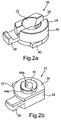
- Fig. 2a shows a schematic representation of a first perspective view of a fixing element 26 for a reflector assembly 10 according to an embodiment of the invention.
- the fixing element 26 is designed here as a rotary latch and has, in particular, a top side 28 and a bottom side 30 (cf. Fig. 2b ) on.
- the upper side 28 has a recess 32 which is frusto-conical here with a cylindrical continuation in the longitudinal direction. In this case, the direction from the upper side 28 of the fixing element 26 to the lower side 30 is referred to as the longitudinal direction of extension.
- the upper side 28 of the fixing element 26 has a rectilinear groove 34. This runs in this example centrally through the recess 32, but can generally be elsewhere.
- a hook-shaped connecting piece 38 is arranged on the outer side 36 of the fixing element 26 for engagement in a counterpart element 20 of the base body 12.
- a stop element 40 is still arranged, which protrudes on the substantially cylindrical outer side 36.
- the outer side 36 of the fixing element 26 is substantially cylindrical in that, in one region, it has a side formed as a flat surface 42 (cf. Fig. 2b ).
- Fig. 2b shows a schematic representation of a second perspective view of the fixing member 26 Fig. 2a , In particular, this representation is 180 ° opposite from Fig. 2a turned.
- the fixing element 26 comprises the same elements as in FIG Fig. 2a described.
- the second connecting element 44 can be seen on the underside 30 of the fixing element 26. This is preferably cylindrical in shape to be inserted into a cylindrical recess 22 of the LED circuit board 14.
- the second connecting element 44 may also be formed of cylindrical elements, such as two half-cylinders, and have recesses 44a and / or elevations 44b, for example, with appropriate design of the recess 22 of the LED circuit board 14 to allow a snap into a locked position.
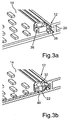
- Fig. 3a shows a schematic representation of a arranged on the LED printed circuit board 14 and the base body 12 fixing element 26 for a reflector assembly 10 according to an embodiment of the invention.
- Good to see here is formed as a recess of the body 12 receiving portion 16 for the LED circuit board 14 and the rail-shaped counterpart element 20 which extends rectilinear and laterally at the edge of the receiving area 16.
- the fixing element 26 shown here is in an hooked position.
- the arranged on the outer side 36 of the fixing member 26 hook-shaped connector 38 engages in the counterpart element 20 of the body 12.
- the fixing member 26 is inserted with its second connecting element 44 in the recess 22 of the LED circuit board 14 and indeed in a recess 22 as they in Fig.
- the fixing element 26 can first be inserted into the recess 22 of the LED circuit board 14, wherein the index 24 so sogt that the fixing element 26 is not applied to the counterpart element 20 or this contacted and thus the fixing member 26 can be rotated, in particular about a longitudinal axis extending along the axis.
- the hook-shaped connecting piece 38 can be hooked into the counterpart element 20 and in the as in Fig. 3a shown position.
- the stop element 40 of the fixing element 26 ensures that this position is very high can be taken precisely.
- Fig. 3b shows again in Fig. 3a
- the recess 32 of the top 28 of the fixing member 26 may be formed as a continuous hole extending from the top 28 to the bottom 30 and manufacturing technology particularly simple and inexpensive is.
- the LED printed circuit board 14 is clamped between the fixing element 26 and the base body 12 and thus fixed to the base body 12.
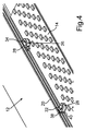
- Fig. 4 shows a schematic representation of two arranged on the LED printed circuit board 14 fixing elements 26 in different positions for a reflector assembly 10 according to an embodiment of the invention.
- the arrangement shown corresponds to the in Fig. 1 illustrated arrangement of the LED circuit board 14 on the base body 12 with now inserted into the two recesses 22 of the LED circuit board 14 second connecting elements 44 of the two illustrated fixing elements 26th
- the fixing element 26 is positioned such that the hook-shaped connecting piece 38 hooks into the counterpart element 20 of the base body 12. This can be done by inserting the fixing element 26 in the recess 22 and turning the fixing member 26 in the hooked position.
- the rotation of the fixing element 26 is characterized by the in Fig. 1 shown index 24 in the counterpart element 20 allows.
- the fixing element 26 is also provided with a stop element 40.
- the first connecting element 50 of the reflector element 46 can be inserted, whereby a point of the reflector element 46 is defined, positioned and fixed.
- the fixing element 26 is positioned such that the flat surface 42 of the outer side 36 of the fixing element 26 bears against the counterpart element 20.
- the groove 34 extending in the upper side 28 of the fixing element 26 is arranged parallel to the flat surface 42 and thus also parallel to the counterpart element 20. This groove 34 allows the reception of a slide element 52 arranged on the reflector element 46 so that the reflector element 46 is precisely parallel to the counterpart element 20 can be aligned.
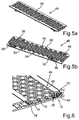
- Fig. 5a shows a schematic representation of a plan view of a reflector element 46 and Fig. 5b a schematic representation of a bottom view of this reflector element 46 for a reflector assembly 10 according to an embodiment of the invention.
- the reflector element 46 in this case comprises a plurality of individual reflectors 48, which are arranged in particular such that each individual reflector 48 is associated with an LED 18 of the LED circuit board 14.
- the geometric configuration of the arrangement of the individual reflectors 48 is thus identical to the geometric configuration of the LED arrangement on the LED printed circuit board 14.
- the reflector element 46 further comprises, in particular on its underside or the side which, when arranged on the LED printed circuit board 14th this is facing, a first connecting element 50 which is inserted into the recess 32 of a fixing member 26 and is formed in this case as an index cylinder. Furthermore, the reflector element 46 has a slide element 52 in order to engage in the groove 34 of a fixing element 26. In addition, spacer elements 54 are still arranged on the reflector element 46, by means of which the reflector element 46 rests on the LED printed circuit board 14 in this arrangement.
- FIGS. 7 and 8 each show a schematic representation of a cross section through a reflector assembly 10 according to embodiments of the invention.
- the reflector element 46 is fixed by the fixing elements 26 on the LED circuit board 14 and precisely positioned, in particular so that each individual reflector 48 as closely as possible via an LED 18 in a predetermined and in particular by the fixing elements 26 and spacers 54 certain distance is arranged
- Fig. 6 shows a cross section through a fixing element 26, in the recess 32, the first connecting element 50 of the reflector element 46 is inserted
- Fig. 7 shows a cross section through a fixing element 26, in the groove 34, a slide member 52 of the reflector element 46 is inserted
- FIG. 8 a cross section with a spacer element 54 shown of the reflector element 46 in order to support this in addition to the LED circuit board 14 and to keep in a predefined distance.
- the fixing elements 26 and the spacer elements 54 are arranged in such a way that they maintain a certain distance from the printed conductors 58 running on the LED printed circuit board 14.
- Fig. 9 shows a schematic representation of a reflector assembly 10 with a plurality of LED printed circuit boards 14, in particular two, and a plurality of reflector elements 46, in particular 4, according to an embodiment of the invention.
- the base body 12 has a receiving region 16, in which a plurality of LED printed circuit boards 14 are arranged.
- a plurality of fixing elements 26 for positioning the reflector elements 46 are arranged in each LED circuit board 14 .
- the reflector elements 46 can thus be plugged onto the LED printed circuit boards 14, preferably in such a way that a first connecting element 50 of a reflector element 46 is inserted into a recess 32 of a fixing element 26 and the slide element 52 of the reflector element 46 into the groove 34 of a further fixing element 26 is introduced.
- each fixing element 26 must have a groove 34, and it is also possible, for example, to provide only every second fixing element 26 with a groove 34 in the upper side 28.
- the base body 12 may further be an extruded aluminum profile and the reflector elements 46 may be metallized plastic injection molded parts. These designs are particularly easy to manufacture and particularly cost-effective options.
- Such a reflector arrangement which enables a positioning of a reflector with respect to an LED arrangement in an extremely accurate manner.
- a positioning is made possible, which can ensure the prescribed safety distances and is so accurate that there are no negative influences on the radiation characteristics.
- the thermally different expansion of the individual materials and the manufacturing tolerances can be accommodated by this reflector arrangement. All this is made possible by the provision of a fixing element, which can be arranged between the reflector and the LED circuit board.
- This fixing element can be used on the one hand to the reflector element at a defined To fix point on the LED circuit board and at the same time, such a fixing element can also be used to align the reflector element, so that the reflector element still remains movable in one direction to intercept manufacturing tolerances and thermal expansions can.
- fixing the fixing of the LED circuit board on the body can be made possible at the same time still.
- the reflector arrangement described here makes it possible to define the position of the boards and thus of the LEDs relative to the receptacle and the reflector element.
- the reflector assembly can be implemented at low cost and with low installation costs. Furthermore, it is still a very low height and thus realize a very flat body.
Landscapes
- Engineering & Computer Science (AREA)
- Microelectronics & Electronic Packaging (AREA)
- General Engineering & Computer Science (AREA)
- Manufacturing & Machinery (AREA)
- Fastening Of Light Sources Or Lamp Holders (AREA)
- Led Device Packages (AREA)
- Securing Globes, Refractors, Reflectors Or The Like (AREA)
Claims (10)
- Système réflecteur (10) comportant un corps de base (12), au moins une carte imprimée à LED (14) et au moins un élément réflecteur (46), le corps de base (12) présentant une zone de réception (16) pour loger l'au moins une carte imprimée à LED (14), l'au moins une carte imprimée à LED (14) étant agencée dans la zone de réception (16) du corps de base (12) et présentant au moins un évidement (22), l'élément réflecteur (46) comportant un premier élément de liaison (50), caractérisé en ce que le système réflecteur (10) comprend au moins un élément de fixation (26), l'élément de fixation (26) comprenant une face supérieure (28) et une face inférieure (30), la face supérieure (28) étant agencée à une distance de la face inférieure (30), la face inférieure (30) comportant un deuxième élément de liaison (44) qui présente une extension longitudinale dans un sens d'extension longitudinale allant de la face supérieure (28) vers la face inférieure (30), la face supérieure (28) de l'élément de fixation (26) présentant un creux (32) dans le sens d'extension longitudinale, le deuxième élément de liaison (44) de l'élément de fixation (26) et l'évidement (22) de la carte imprimée à LED (14) étant réalisés de telle sorte que le deuxième élément de liaison (44) peut être introduit dans l'évidement (22) de la carte imprimée à LED (14), de sorte que la face inférieure (30) de l'élément de fixation (26) peut être mise en contact avec la carte imprimée à LED (14), et le creux (32) de la face supérieure (28) de l'élément de fixation (26) et le premier élément de liaison (50) de l'élément réflecteur (46) étant réalisés de telle sorte que le premier élément de liaison (50) de l'élément réflecteur (46) peut être introduit dans le creux (32) de la face supérieure (28) de l'élément de fixation (26), de telle sorte que l'élément réflecteur (46) peut être mis en contact avec la face supérieure (28) de l'élément de fixation (26).
- Système réflecteur (10) selon la revendication 1, le deuxième élément de liaison (44) présentant, sur la face inférieure (30) de l'élément de fixation (26), une forme de base cylindrique et l'évidement (22) de la carte imprimée à LED (14) ayant une forme cylindrique telle que l'élément de fixation (26) avec le deuxième élément de liaison (44) peut, lorsqu'il est introduit dans l'évidement (22) de la carte imprimée à LED (14), tourner autour d'un axe allant dans le sens d'extension longitudinale.
- Système réflecteur (10) selon l'une des revendications précédentes, l'élément de fixation (26) présentant une face extérieure (36) qui est agencée entre la face supérieure (28) et la face inférieure (30) de l'élément de fixation (26), une pièce de liaison en forme de crochet (38) étant agencée sur la face extérieure (36), le corps de base (12) présentant au moins un élément complémentaire (20) qui est réalisé de telle sorte que la pièce de liaison en forme de crochet (38) peut être accrochée dans l'élément complémentaire (20).
- Système réflecteur (10) selon l'une des revendications précédentes, l'élément complémentaire (20) étant agencé au moins en partie le long de la zone de réception (16) de la carte imprimée à LED (14), l'élément complémentaire (20) étant réalisé de telle sorte que la pièce de liaison en forme de crochet (38) de l'élément de fixation (26) peut, lorsque le deuxième élément de liaison (44) de la face inférieure (30) de l'élément de fixation (26) est introduit dans l'évidement (22) de la carte imprimée à LED (14), être accroché dans l'élément complémentaire (20) par rotation de l'élément de fixation (26) autour de l'axe allant dans le sens de l'extension longitudinale.
- Système réflecteur (10) selon l'une des revendications précédentes, le creux (32) de la face supérieure (28) de l'élément de fixation (26) et le premier élément de liaison (50) de l'élément réflecteur (46) étant réalisés sous une forme ronde dans une section perpendiculaire au sens de l'extension longitudinale, de sorte que l'élément réflecteur (46) peut, lorsque l'élément de liaison (50) est introduit dans le creux (32), tourner autour d'un axe allant en direction du sens de l'extension longitudinale.
- Système réflecteur (10) selon l'une des revendications précédentes, la face supérieure (28) de l'élément de fixation (26) présentant une rainure rectiligne (34) perpendiculaire au sens de l'extension longitudinale et l'élément réflecteur (46) présentant un élément de patin (52) qui est réalisé de telle sorte qu'il peut être introduit dans la rainure (34).
- Système réflecteur (10) selon l'une des revendications précédentes, la face extérieure (36) de l'élément de fixation (26) étant, au moins dans une zone, réalisé en tant que surface plane (42), de telle sorte que l'élément de fixation (26) peut, au moyen de cette surface plane (42), être orienté sur l'élément complémentaire (20) du corps de base (12).
- Système réflecteur selon l'une des revendications précédentes, sur la face extérieure (36) de l'élément de fixation (26) étant agencé un élément de butée (40) au moyen duquel l'élément de fixation (26) peut tourner jusque dans une position prédéterminable lorsque le deuxième élément de liaison (44) est introduit dans l'évidement (22) de la carte imprimée à LED (14).
- Système réflecteur (10) selon l'une des revendications précédentes, l'élément réflecteur (46) comportant des éléments d'écartement (54) ayant une longueur prédéterminée dans le sens de l'extension longitudinale, de sorte que, lorsque le premier élément de liaison (50) de l'élément réflecteur (46) est introduit dans le creux (32) de la face supérieure (28) de l'élément de fixation (26) et que le deuxième élément de liaison (44) de l'élément de fixation (26) est introduit dans l'évidement (22) de la carte imprimée à LED (14), les éléments d'écartement (54) sont en contact avec la carte imprimée à LED (14).
- Système réflecteur (10) selon l'une des revendications précédentes, l'élément réflecteur (46) comprenant des éléments d'encliquetage (56) qui sont réalisés pour s'encliqueter, lorsque l'élément réflecteur (46) est agencé sur la carte imprimée à LED (14), sous des surfaces d'appui du corps de bases (12), qui sont situées au moins en partie le long de la zone de réception (16) de la carte imprimée à LED (14).
Applications Claiming Priority (2)
| Application Number | Priority Date | Filing Date | Title |
|---|---|---|---|
| DE102012220977.8A DE102012220977A1 (de) | 2012-11-16 | 2012-11-16 | Reflektoranordnung |
| PCT/EP2013/067315 WO2014075826A1 (fr) | 2012-11-16 | 2013-08-20 | Système de réflecteur |
Publications (2)
| Publication Number | Publication Date |
|---|---|
| EP2921035A1 EP2921035A1 (fr) | 2015-09-23 |
| EP2921035B1 true EP2921035B1 (fr) | 2016-11-02 |
Family
ID=49080851
Family Applications (1)
| Application Number | Title | Priority Date | Filing Date |
|---|---|---|---|
| EP13753605.8A Not-in-force EP2921035B1 (fr) | 2012-11-16 | 2013-08-20 | Système de réflecteur |
Country Status (3)
| Country | Link |
|---|---|
| EP (1) | EP2921035B1 (fr) |
| DE (1) | DE102012220977A1 (fr) |
| WO (1) | WO2014075826A1 (fr) |
Cited By (1)
| Publication number | Priority date | Publication date | Assignee | Title |
|---|---|---|---|---|
| DE102017105470A1 (de) | 2017-03-15 | 2018-09-20 | Vossloh-Schwabe Deutschland Gmbh | Leuchtenbaugruppe |
Families Citing this family (3)
| Publication number | Priority date | Publication date | Assignee | Title |
|---|---|---|---|---|
| DE202013010052U1 (de) * | 2013-11-06 | 2015-02-10 | Zumtobel Lighting Gmbh | Anordnung zur Lichtabgabe sowie Leuchte mit einer solchen Anordnung |
| DE102016124556A1 (de) | 2016-12-15 | 2018-06-21 | Osram Gmbh | Leuchte mit Tragschiene und Befestigungselement für eine Platine |
| DE102016124542A1 (de) | 2016-12-15 | 2018-06-21 | Osram Gmbh | Leuchte mit Positionierungselement zum Halten von Platine und optischen Bauteilen |
Family Cites Families (9)
| Publication number | Priority date | Publication date | Assignee | Title |
|---|---|---|---|---|
| DE10324909B4 (de) * | 2003-05-30 | 2017-09-07 | Osram Opto Semiconductors Gmbh | Gehäuse für ein strahlungsemittierendes Bauelement, Verfahren zu dessen Herstellung und strahlungsemittierendes Bauelement |
| US7086754B2 (en) * | 2003-10-31 | 2006-08-08 | Brocade Communications Systems, Inc. | Light reflector and barrier for light emitting diodes |
| US7281818B2 (en) * | 2003-12-11 | 2007-10-16 | Dialight Corporation | Light reflector device for light emitting diode (LED) array |
| EP1998105A1 (fr) * | 2007-05-29 | 2008-12-03 | Martin Professional A/S | Dispositif d'éclairage avec optique remplaçable |
| CN101556032B (zh) * | 2008-04-09 | 2010-09-29 | 富准精密工业(深圳)有限公司 | 发光二极管灯具 |
| MX2008007268A (es) * | 2008-06-06 | 2009-12-07 | Servicios Condumex Sa | Luminaria electronica a base de diodos emisores de luz. |
| DE102009053957A1 (de) * | 2009-11-19 | 2011-06-01 | Osram Gesellschaft mit beschränkter Haftung | Reflektor für eine Leuchtvorrichtung und Leuchtvorrichtung |
| ES2720356T3 (es) * | 2010-01-05 | 2019-07-19 | Signify Holding Bv | Motor de luz extraíble |
| CN103460813B (zh) * | 2011-03-22 | 2017-07-11 | 飞利浦照明控股有限公司 | 用于安装多个发光元件的基板 |
-
2012
- 2012-11-16 DE DE102012220977.8A patent/DE102012220977A1/de not_active Withdrawn
-
2013
- 2013-08-20 EP EP13753605.8A patent/EP2921035B1/fr not_active Not-in-force
- 2013-08-20 WO PCT/EP2013/067315 patent/WO2014075826A1/fr not_active Ceased
Cited By (2)
| Publication number | Priority date | Publication date | Assignee | Title |
|---|---|---|---|---|
| DE102017105470A1 (de) | 2017-03-15 | 2018-09-20 | Vossloh-Schwabe Deutschland Gmbh | Leuchtenbaugruppe |
| DE102017105470B4 (de) | 2017-03-15 | 2021-07-29 | Vossloh-Schwabe Deutschland Gmbh | Leuchtenbaugruppe |
Also Published As
| Publication number | Publication date |
|---|---|
| DE102012220977A1 (de) | 2014-05-22 |
| EP2921035A1 (fr) | 2015-09-23 |
| WO2014075826A1 (fr) | 2014-05-22 |
Similar Documents
| Publication | Publication Date | Title |
|---|---|---|
| EP3593413B1 (fr) | Connecteur circulaire femelle conçu pour une carte de circuits imprimés pouvant être disposée sur ce connecteur | |
| DE202008007783U1 (de) | In einem Loch befestigbares Halteelement | |
| EP2921035B1 (fr) | Système de réflecteur | |
| EP4033612A1 (fr) | Châssis-support en plusieurs parties procédé de montage et d'implantation | |
| DE3214528A1 (de) | Vorrichtung zur festlegung von geraeten in einer frontplatte oder schalttafel | |
| DE2911972A1 (de) | Anschlussklemme, vorzugsweise zum einbau auf leiterplatten von gedruckten schaltungen | |
| DE102008034775A1 (de) | Vorrichtung zum Verbinden zweier Schränke für Schaltgeräte | |
| DE1927066C3 (de) | Führungsteil für gedruckte Schaltungsplatten | |
| EP3608588B1 (fr) | Ressort de maintien pour luminaire | |
| EP2514287B1 (fr) | Unité modulaire | |
| DE102013213822B4 (de) | Bauteilanordnung für ein Lenkrad | |
| EP4223180B1 (fr) | Système de rayonnage | |
| EP3281252B1 (fr) | Module en nid d'abeille | |
| DE2715056C3 (de) | Halterung für ein Substrat in einer Mikrowellenbaugruppe | |
| EP3067465A1 (fr) | Dispositif de connexion | |
| EP2997315B1 (fr) | Système pour la fixation de rails de montage | |
| DE202011052516U1 (de) | Befestigungseinrichtung für ein Flächenelement in einem unterhaltungselektronischen Gerät | |
| EP2090789B1 (fr) | Connecteur pour tiges de profil en forme de cannelure et agencement de connexion | |
| EP3578731B1 (fr) | Élément de support et système de façade pourvu d'un tel élément de support | |
| EP3339724B1 (fr) | Éclairage à rail de support et élément de fixation pour une platine | |
| DE2510177A1 (de) | Steckbare flachkunststoffklammer | |
| DE3844310A1 (de) | Halterung fuer freistehende elektronische bauteile | |
| EP1611652B1 (fr) | Element de verrouillage pour fixer un appareil d'installation pour des barres omnibus | |
| DE10315501B3 (de) | Verriegelungselement zur Befestigung eines Installationsgerätes für Sammelschienen sowie Installationsgerät mit einem solchen Verriegelungselement | |
| DE102008007147A1 (de) | Klemmträgerprofil |
Legal Events
| Date | Code | Title | Description |
|---|---|---|---|
| PUAI | Public reference made under article 153(3) epc to a published international application that has entered the european phase |
Free format text: ORIGINAL CODE: 0009012 |
|
| 17P | Request for examination filed |
Effective date: 20150616 |
|
| AK | Designated contracting states |
Kind code of ref document: A1 Designated state(s): AL AT BE BG CH CY CZ DE DK EE ES FI FR GB GR HR HU IE IS IT LI LT LU LV MC MK MT NL NO PL PT RO RS SE SI SK SM TR |
|
| AX | Request for extension of the european patent |
Extension state: BA ME |
|
| DAX | Request for extension of the european patent (deleted) | ||
| GRAP | Despatch of communication of intention to grant a patent |
Free format text: ORIGINAL CODE: EPIDOSNIGR1 |
|
| INTG | Intention to grant announced |
Effective date: 20160610 |
|
| GRAS | Grant fee paid |
Free format text: ORIGINAL CODE: EPIDOSNIGR3 |
|
| GRAA | (expected) grant |
Free format text: ORIGINAL CODE: 0009210 |
|
| AK | Designated contracting states |
Kind code of ref document: B1 Designated state(s): AL AT BE BG CH CY CZ DE DK EE ES FI FR GB GR HR HU IE IS IT LI LT LU LV MC MK MT NL NO PL PT RO RS SE SI SK SM TR |
|
| REG | Reference to a national code |
Ref country code: GB Ref legal event code: FG4D Free format text: NOT ENGLISH |
|
| REG | Reference to a national code |
Ref country code: AT Ref legal event code: REF Ref document number: 842991 Country of ref document: AT Kind code of ref document: T Effective date: 20161115 Ref country code: CH Ref legal event code: EP |
|
| REG | Reference to a national code |
Ref country code: IE Ref legal event code: FG4D Free format text: LANGUAGE OF EP DOCUMENT: GERMAN |
|
| REG | Reference to a national code |
Ref country code: DE Ref legal event code: R096 Ref document number: 502013005205 Country of ref document: DE |
|
| REG | Reference to a national code |
Ref country code: CH Ref legal event code: NV Representative=s name: BOVARD AG PATENT- UND MARKENANWAELTE, CH |
|
| PG25 | Lapsed in a contracting state [announced via postgrant information from national office to epo] |
Ref country code: LV Free format text: LAPSE BECAUSE OF FAILURE TO SUBMIT A TRANSLATION OF THE DESCRIPTION OR TO PAY THE FEE WITHIN THE PRESCRIBED TIME-LIMIT Effective date: 20161102 |
|
| REG | Reference to a national code |
Ref country code: NL Ref legal event code: MP Effective date: 20161102 |
|
| REG | Reference to a national code |
Ref country code: LT Ref legal event code: MG4D |
|
| PG25 | Lapsed in a contracting state [announced via postgrant information from national office to epo] |
Ref country code: NL Free format text: LAPSE BECAUSE OF FAILURE TO SUBMIT A TRANSLATION OF THE DESCRIPTION OR TO PAY THE FEE WITHIN THE PRESCRIBED TIME-LIMIT Effective date: 20161102 Ref country code: SE Free format text: LAPSE BECAUSE OF FAILURE TO SUBMIT A TRANSLATION OF THE DESCRIPTION OR TO PAY THE FEE WITHIN THE PRESCRIBED TIME-LIMIT Effective date: 20161102 Ref country code: LT Free format text: LAPSE BECAUSE OF FAILURE TO SUBMIT A TRANSLATION OF THE DESCRIPTION OR TO PAY THE FEE WITHIN THE PRESCRIBED TIME-LIMIT Effective date: 20161102 Ref country code: GR Free format text: LAPSE BECAUSE OF FAILURE TO SUBMIT A TRANSLATION OF THE DESCRIPTION OR TO PAY THE FEE WITHIN THE PRESCRIBED TIME-LIMIT Effective date: 20170203 Ref country code: NO Free format text: LAPSE BECAUSE OF FAILURE TO SUBMIT A TRANSLATION OF THE DESCRIPTION OR TO PAY THE FEE WITHIN THE PRESCRIBED TIME-LIMIT Effective date: 20170202 |
|
| PG25 | Lapsed in a contracting state [announced via postgrant information from national office to epo] |
Ref country code: HR Free format text: LAPSE BECAUSE OF FAILURE TO SUBMIT A TRANSLATION OF THE DESCRIPTION OR TO PAY THE FEE WITHIN THE PRESCRIBED TIME-LIMIT Effective date: 20161102 Ref country code: IS Free format text: LAPSE BECAUSE OF FAILURE TO SUBMIT A TRANSLATION OF THE DESCRIPTION OR TO PAY THE FEE WITHIN THE PRESCRIBED TIME-LIMIT Effective date: 20170302 Ref country code: RS Free format text: LAPSE BECAUSE OF FAILURE TO SUBMIT A TRANSLATION OF THE DESCRIPTION OR TO PAY THE FEE WITHIN THE PRESCRIBED TIME-LIMIT Effective date: 20161102 Ref country code: FI Free format text: LAPSE BECAUSE OF FAILURE TO SUBMIT A TRANSLATION OF THE DESCRIPTION OR TO PAY THE FEE WITHIN THE PRESCRIBED TIME-LIMIT Effective date: 20161102 Ref country code: PL Free format text: LAPSE BECAUSE OF FAILURE TO SUBMIT A TRANSLATION OF THE DESCRIPTION OR TO PAY THE FEE WITHIN THE PRESCRIBED TIME-LIMIT Effective date: 20161102 Ref country code: PT Free format text: LAPSE BECAUSE OF FAILURE TO SUBMIT A TRANSLATION OF THE DESCRIPTION OR TO PAY THE FEE WITHIN THE PRESCRIBED TIME-LIMIT Effective date: 20170302 Ref country code: ES Free format text: LAPSE BECAUSE OF FAILURE TO SUBMIT A TRANSLATION OF THE DESCRIPTION OR TO PAY THE FEE WITHIN THE PRESCRIBED TIME-LIMIT Effective date: 20161102 |
|
| PG25 | Lapsed in a contracting state [announced via postgrant information from national office to epo] |
Ref country code: SK Free format text: LAPSE BECAUSE OF FAILURE TO SUBMIT A TRANSLATION OF THE DESCRIPTION OR TO PAY THE FEE WITHIN THE PRESCRIBED TIME-LIMIT Effective date: 20161102 Ref country code: EE Free format text: LAPSE BECAUSE OF FAILURE TO SUBMIT A TRANSLATION OF THE DESCRIPTION OR TO PAY THE FEE WITHIN THE PRESCRIBED TIME-LIMIT Effective date: 20161102 Ref country code: DK Free format text: LAPSE BECAUSE OF FAILURE TO SUBMIT A TRANSLATION OF THE DESCRIPTION OR TO PAY THE FEE WITHIN THE PRESCRIBED TIME-LIMIT Effective date: 20161102 Ref country code: RO Free format text: LAPSE BECAUSE OF FAILURE TO SUBMIT A TRANSLATION OF THE DESCRIPTION OR TO PAY THE FEE WITHIN THE PRESCRIBED TIME-LIMIT Effective date: 20161102 Ref country code: CZ Free format text: LAPSE BECAUSE OF FAILURE TO SUBMIT A TRANSLATION OF THE DESCRIPTION OR TO PAY THE FEE WITHIN THE PRESCRIBED TIME-LIMIT Effective date: 20161102 |
|
| REG | Reference to a national code |
Ref country code: DE Ref legal event code: R097 Ref document number: 502013005205 Country of ref document: DE |
|
| REG | Reference to a national code |
Ref country code: FR Ref legal event code: PLFP Year of fee payment: 5 |
|
| PG25 | Lapsed in a contracting state [announced via postgrant information from national office to epo] |
Ref country code: SM Free format text: LAPSE BECAUSE OF FAILURE TO SUBMIT A TRANSLATION OF THE DESCRIPTION OR TO PAY THE FEE WITHIN THE PRESCRIBED TIME-LIMIT Effective date: 20161102 Ref country code: BG Free format text: LAPSE BECAUSE OF FAILURE TO SUBMIT A TRANSLATION OF THE DESCRIPTION OR TO PAY THE FEE WITHIN THE PRESCRIBED TIME-LIMIT Effective date: 20170202 |
|
| PLBE | No opposition filed within time limit |
Free format text: ORIGINAL CODE: 0009261 |
|
| STAA | Information on the status of an ep patent application or granted ep patent |
Free format text: STATUS: NO OPPOSITION FILED WITHIN TIME LIMIT |
|
| 26N | No opposition filed |
Effective date: 20170803 |
|
| PGFP | Annual fee paid to national office [announced via postgrant information from national office to epo] |
Ref country code: GB Payment date: 20170822 Year of fee payment: 5 Ref country code: CH Payment date: 20170821 Year of fee payment: 5 Ref country code: IT Payment date: 20170828 Year of fee payment: 5 |
|
| PG25 | Lapsed in a contracting state [announced via postgrant information from national office to epo] |
Ref country code: SI Free format text: LAPSE BECAUSE OF FAILURE TO SUBMIT A TRANSLATION OF THE DESCRIPTION OR TO PAY THE FEE WITHIN THE PRESCRIBED TIME-LIMIT Effective date: 20161102 |
|
| PG25 | Lapsed in a contracting state [announced via postgrant information from national office to epo] |
Ref country code: MC Free format text: LAPSE BECAUSE OF FAILURE TO SUBMIT A TRANSLATION OF THE DESCRIPTION OR TO PAY THE FEE WITHIN THE PRESCRIBED TIME-LIMIT Effective date: 20161102 |
|
| REG | Reference to a national code |
Ref country code: IE Ref legal event code: MM4A |
|
| REG | Reference to a national code |
Ref country code: BE Ref legal event code: MM Effective date: 20170831 |
|
| PG25 | Lapsed in a contracting state [announced via postgrant information from national office to epo] |
Ref country code: LU Free format text: LAPSE BECAUSE OF NON-PAYMENT OF DUE FEES Effective date: 20170820 |
|
| PG25 | Lapsed in a contracting state [announced via postgrant information from national office to epo] |
Ref country code: IE Free format text: LAPSE BECAUSE OF NON-PAYMENT OF DUE FEES Effective date: 20170820 |
|
| REG | Reference to a national code |
Ref country code: FR Ref legal event code: PLFP Year of fee payment: 6 |
|
| PG25 | Lapsed in a contracting state [announced via postgrant information from national office to epo] |
Ref country code: BE Free format text: LAPSE BECAUSE OF NON-PAYMENT OF DUE FEES Effective date: 20170831 |
|
| PG25 | Lapsed in a contracting state [announced via postgrant information from national office to epo] |
Ref country code: MT Free format text: LAPSE BECAUSE OF FAILURE TO SUBMIT A TRANSLATION OF THE DESCRIPTION OR TO PAY THE FEE WITHIN THE PRESCRIBED TIME-LIMIT Effective date: 20161102 |
|
| REG | Reference to a national code |
Ref country code: CH Ref legal event code: PL |
|
| GBPC | Gb: european patent ceased through non-payment of renewal fee |
Effective date: 20180820 |
|
| PG25 | Lapsed in a contracting state [announced via postgrant information from national office to epo] |
Ref country code: CH Free format text: LAPSE BECAUSE OF NON-PAYMENT OF DUE FEES Effective date: 20180831 Ref country code: LI Free format text: LAPSE BECAUSE OF NON-PAYMENT OF DUE FEES Effective date: 20180831 |
|
| PG25 | Lapsed in a contracting state [announced via postgrant information from national office to epo] |
Ref country code: HU Free format text: LAPSE BECAUSE OF FAILURE TO SUBMIT A TRANSLATION OF THE DESCRIPTION OR TO PAY THE FEE WITHIN THE PRESCRIBED TIME-LIMIT; INVALID AB INITIO Effective date: 20130820 |
|
| PG25 | Lapsed in a contracting state [announced via postgrant information from national office to epo] |
Ref country code: IT Free format text: LAPSE BECAUSE OF NON-PAYMENT OF DUE FEES Effective date: 20180820 |
|
| PG25 | Lapsed in a contracting state [announced via postgrant information from national office to epo] |
Ref country code: GB Free format text: LAPSE BECAUSE OF NON-PAYMENT OF DUE FEES Effective date: 20180820 Ref country code: CY Free format text: LAPSE BECAUSE OF FAILURE TO SUBMIT A TRANSLATION OF THE DESCRIPTION OR TO PAY THE FEE WITHIN THE PRESCRIBED TIME-LIMIT Effective date: 20161102 |
|
| PG25 | Lapsed in a contracting state [announced via postgrant information from national office to epo] |
Ref country code: MK Free format text: LAPSE BECAUSE OF FAILURE TO SUBMIT A TRANSLATION OF THE DESCRIPTION OR TO PAY THE FEE WITHIN THE PRESCRIBED TIME-LIMIT Effective date: 20161102 |
|
| REG | Reference to a national code |
Ref country code: DE Ref legal event code: R082 Ref document number: 502013005205 Country of ref document: DE Representative=s name: BOEHMERT & BOEHMERT ANWALTSPARTNERSCHAFT MBB -, DE Ref country code: DE Ref legal event code: R081 Ref document number: 502013005205 Country of ref document: DE Owner name: SITECO GMBH, DE Free format text: FORMER OWNER: OSRAM GMBH, 80807 MUENCHEN, DE |
|
| PG25 | Lapsed in a contracting state [announced via postgrant information from national office to epo] |
Ref country code: TR Free format text: LAPSE BECAUSE OF FAILURE TO SUBMIT A TRANSLATION OF THE DESCRIPTION OR TO PAY THE FEE WITHIN THE PRESCRIBED TIME-LIMIT Effective date: 20161102 |
|
| PG25 | Lapsed in a contracting state [announced via postgrant information from national office to epo] |
Ref country code: AL Free format text: LAPSE BECAUSE OF FAILURE TO SUBMIT A TRANSLATION OF THE DESCRIPTION OR TO PAY THE FEE WITHIN THE PRESCRIBED TIME-LIMIT Effective date: 20161102 |
|
| REG | Reference to a national code |
Ref country code: AT Ref legal event code: PC Ref document number: 842991 Country of ref document: AT Kind code of ref document: T Owner name: SITECO GMBH, DE Effective date: 20210629 |
|
| PGFP | Annual fee paid to national office [announced via postgrant information from national office to epo] |
Ref country code: DE Payment date: 20220822 Year of fee payment: 10 Ref country code: AT Payment date: 20220818 Year of fee payment: 10 |
|
| PGFP | Annual fee paid to national office [announced via postgrant information from national office to epo] |
Ref country code: FR Payment date: 20220822 Year of fee payment: 10 |
|
| REG | Reference to a national code |
Ref country code: DE Ref legal event code: R119 Ref document number: 502013005205 Country of ref document: DE |
|
| REG | Reference to a national code |
Ref country code: AT Ref legal event code: MM01 Ref document number: 842991 Country of ref document: AT Kind code of ref document: T Effective date: 20230820 |
|
| PG25 | Lapsed in a contracting state [announced via postgrant information from national office to epo] |
Ref country code: AT Free format text: LAPSE BECAUSE OF NON-PAYMENT OF DUE FEES Effective date: 20230820 |
|
| PG25 | Lapsed in a contracting state [announced via postgrant information from national office to epo] |
Ref country code: AT Free format text: LAPSE BECAUSE OF NON-PAYMENT OF DUE FEES Effective date: 20230820 |
|
| PG25 | Lapsed in a contracting state [announced via postgrant information from national office to epo] |
Ref country code: FR Free format text: LAPSE BECAUSE OF NON-PAYMENT OF DUE FEES Effective date: 20230831 Ref country code: DE Free format text: LAPSE BECAUSE OF NON-PAYMENT OF DUE FEES Effective date: 20240301 |