EP2921114B1 - Procédé et appareil permettant de modifier une direction ou position d'une ligne de sélection de plan sur la base d'un motif - Google Patents
Procédé et appareil permettant de modifier une direction ou position d'une ligne de sélection de plan sur la base d'un motif Download PDFInfo
- Publication number
- EP2921114B1 EP2921114B1 EP14197361.0A EP14197361A EP2921114B1 EP 2921114 B1 EP2921114 B1 EP 2921114B1 EP 14197361 A EP14197361 A EP 14197361A EP 2921114 B1 EP2921114 B1 EP 2921114B1
- Authority
- EP
- European Patent Office
- Prior art keywords
- selection line
- plane selection
- plane
- image
- pattern
- Prior art date
- Legal status (The legal status is an assumption and is not a legal conclusion. Google has not performed a legal analysis and makes no representation as to the accuracy of the status listed.)
- Active
Links
Images




Classifications
-
- A—HUMAN NECESSITIES
- A61—MEDICAL OR VETERINARY SCIENCE; HYGIENE
- A61B—DIAGNOSIS; SURGERY; IDENTIFICATION
- A61B8/00—Diagnosis using ultrasonic, sonic or infrasonic waves
- A61B8/13—Tomography
- A61B8/14—Echo-tomography
-
- A—HUMAN NECESSITIES
- A61—MEDICAL OR VETERINARY SCIENCE; HYGIENE
- A61B—DIAGNOSIS; SURGERY; IDENTIFICATION
- A61B8/00—Diagnosis using ultrasonic, sonic or infrasonic waves
- A61B8/46—Ultrasonic, sonic or infrasonic diagnostic devices with special arrangements for interfacing with the operator or the patient
- A61B8/461—Displaying means of special interest
- A61B8/466—Displaying means of special interest adapted to display 3D data
-
- A—HUMAN NECESSITIES
- A61—MEDICAL OR VETERINARY SCIENCE; HYGIENE
- A61B—DIAGNOSIS; SURGERY; IDENTIFICATION
- A61B8/00—Diagnosis using ultrasonic, sonic or infrasonic waves
- A61B8/46—Ultrasonic, sonic or infrasonic diagnostic devices with special arrangements for interfacing with the operator or the patient
- A61B8/467—Ultrasonic, sonic or infrasonic diagnostic devices with special arrangements for interfacing with the operator or the patient characterised by special input means
- A61B8/469—Ultrasonic, sonic or infrasonic diagnostic devices with special arrangements for interfacing with the operator or the patient characterised by special input means for selection of a region of interest
-
- A—HUMAN NECESSITIES
- A61—MEDICAL OR VETERINARY SCIENCE; HYGIENE
- A61B—DIAGNOSIS; SURGERY; IDENTIFICATION
- A61B8/00—Diagnosis using ultrasonic, sonic or infrasonic waves
- A61B8/48—Diagnostic techniques
- A61B8/483—Diagnostic techniques involving the acquisition of a 3D volume of data
-
- A—HUMAN NECESSITIES
- A61—MEDICAL OR VETERINARY SCIENCE; HYGIENE
- A61B—DIAGNOSIS; SURGERY; IDENTIFICATION
- A61B8/00—Diagnosis using ultrasonic, sonic or infrasonic waves
- A61B8/52—Devices using data or image processing specially adapted for diagnosis using ultrasonic, sonic or infrasonic waves
- A61B8/5215—Devices using data or image processing specially adapted for diagnosis using ultrasonic, sonic or infrasonic waves involving processing of medical diagnostic data
- A61B8/523—Devices using data or image processing specially adapted for diagnosis using ultrasonic, sonic or infrasonic waves involving processing of medical diagnostic data for generating planar views from image data in a user selectable plane not corresponding to the acquisition plane
-
- G—PHYSICS
- G06—COMPUTING OR CALCULATING; COUNTING
- G06T—IMAGE DATA PROCESSING OR GENERATION, IN GENERAL
- G06T3/00—Geometric image transformations in the plane of the image
-
- G—PHYSICS
- G06—COMPUTING OR CALCULATING; COUNTING
- G06T—IMAGE DATA PROCESSING OR GENERATION, IN GENERAL
- G06T7/00—Image analysis
- G06T7/0002—Inspection of images, e.g. flaw detection
- G06T7/0012—Biomedical image inspection
-
- G—PHYSICS
- G01—MEASURING; TESTING
- G01S—RADIO DIRECTION-FINDING; RADIO NAVIGATION; DETERMINING DISTANCE OR VELOCITY BY USE OF RADIO WAVES; LOCATING OR PRESENCE-DETECTING BY USE OF THE REFLECTION OR RERADIATION OF RADIO WAVES; ANALOGOUS ARRANGEMENTS USING OTHER WAVES
- G01S7/00—Details of systems according to groups G01S13/00, G01S15/00, G01S17/00
- G01S7/52—Details of systems according to groups G01S13/00, G01S15/00, G01S17/00 of systems according to group G01S15/00
- G01S7/52017—Details of systems according to groups G01S13/00, G01S15/00, G01S17/00 of systems according to group G01S15/00 particularly adapted to short-range imaging
- G01S7/52053—Display arrangements
- G01S7/52057—Cathode ray tube displays
- G01S7/5206—Two-dimensional coordinated display of distance and direction; B-scan display
-
- G—PHYSICS
- G01—MEASURING; TESTING
- G01S—RADIO DIRECTION-FINDING; RADIO NAVIGATION; DETERMINING DISTANCE OR VELOCITY BY USE OF RADIO WAVES; LOCATING OR PRESENCE-DETECTING BY USE OF THE REFLECTION OR RERADIATION OF RADIO WAVES; ANALOGOUS ARRANGEMENTS USING OTHER WAVES
- G01S7/00—Details of systems according to groups G01S13/00, G01S15/00, G01S17/00
- G01S7/52—Details of systems according to groups G01S13/00, G01S15/00, G01S17/00 of systems according to group G01S15/00
- G01S7/52017—Details of systems according to groups G01S13/00, G01S15/00, G01S17/00 of systems according to group G01S15/00 particularly adapted to short-range imaging
- G01S7/52053—Display arrangements
- G01S7/52057—Cathode ray tube displays
- G01S7/52073—Production of cursor lines, markers or indicia by electronic means
-
- G—PHYSICS
- G01—MEASURING; TESTING
- G01S—RADIO DIRECTION-FINDING; RADIO NAVIGATION; DETERMINING DISTANCE OR VELOCITY BY USE OF RADIO WAVES; LOCATING OR PRESENCE-DETECTING BY USE OF THE REFLECTION OR RERADIATION OF RADIO WAVES; ANALOGOUS ARRANGEMENTS USING OTHER WAVES
- G01S7/00—Details of systems according to groups G01S13/00, G01S15/00, G01S17/00
- G01S7/52—Details of systems according to groups G01S13/00, G01S15/00, G01S17/00 of systems according to group G01S15/00
- G01S7/52017—Details of systems according to groups G01S13/00, G01S15/00, G01S17/00 of systems according to group G01S15/00 particularly adapted to short-range imaging
- G01S7/52053—Display arrangements
- G01S7/52057—Cathode ray tube displays
- G01S7/52074—Composite displays, e.g. split-screen displays; Combination of multiple images or of images and alphanumeric tabular information
Definitions
- One or more embodiments of the present invention relate to a method and apparatus for changing at least one of a direction and position of a plane selection line, based on a pattern.
- Ultrasound diagnostic apparatuses transfer an ultrasound signal from a surface of an object to a certain part of a human body, and obtain a tomography image of a soft tissue or an image of blood flow by using information of an ultrasound signal reflected from an internal tissue of the human body.
- ultrasound diagnostic apparatuses transmits an ultrasound signal, which is generated by a transducer of a probe, to an object, and receives information of an echo signal reflected from the object to obtain an image of an internal part of the object.
- the ultrasound diagnostic apparatuses display information about an object in real time.
- ultrasound diagnostic apparatuses have high stability because an object is not exposed to X-rays or the like, and thus are being widely used along with other image diagnostic apparatuses such as X-ray diagnostic apparatuses, computerized tomography (CT) scanners, magnetic resonance imaging (MRI) apparatuses, and nuclear medicine diagnostic apparatuses.
- the EP 2 700 364 A2 relates to a method of managing an ultrasound image, the method including storing a plurality of pieces of setting information to respectively match a plurality of observation operations for diagnosing an object, each of the plurality of pieces of setting information including at least one from among information about an observation plane that splits ultrasound volume data in a predetermined direction, information about a split method of splitting the ultrasound volume data, and information about a reference point; displaying a plurality of plane images for a current observation operation, wherein the plurality of plane images are obtained based on a piece of the setting information matching the current observation operation; storing an image selected from among the plurality of plane images according to an external input signal such that the selected image matches the current observation operation.
- the US 2005/049494 A1 provides a method and apparatus for presenting multiple enhanced images of different anatomic features is provided.
- An ultrasonic volume data set having multiple anatomic features is acquired.
- Multiple enhanced images are presented simultaneously based on the multiple anatomic features within the data set.
- the US 2011/282207 A1 relates to an apparatus including a slice image generation unit, a three-dimensional image generation unit, a display unit, a setting unit, an updating unit, and a changing unit.
- the slice image generation unit generates the data of slice images based on a volume data.
- the three-dimensional image generation unit generates the data of a three-dimensional image based on the volume data.
- the display unit displays the slice images and the three-dimensional image.
- the setting unit sets the vector on the first slice image of the displayed slice images in accordance with an instruction from an operator.
- the updating unit updates the displayed three-dimensional image based on the vector.
- the changing unit changes the position of a slice of a remaining slice image of the displayed slice images to a position where the slice intersects the vector and is perpendicular to the slice of the first slice image.
- One or more embodiments of the present invention include a method of changing at least one of a direction and position of a plane selection line based on a pattern for acquiring an image of a plane of interest (POI) of an object.
- PHI plane of interest
- the term “medical image” may denote an ultrasonic image, an X-ray image, a magnetic resonance (MR) image, or a computerized tomography (CT) image.
- An “ultrasonic image” refers to an image of an object obtained using an ultrasonic wave.
- object may include a person or an animal, or a part of a person or an animal.
- the object may include the liver, the heart, the womb, the brain, a breast, the abdomen, or a blood vessel.
- the "object” may include a phantom.
- the phantom means a material having a volume that is approximately the intensity and effective atomic number of a living thing, and may include a spherical phantom having a property similar to a human body.
- the term "user" used herein is a medical expert, and may be a doctor, a nurse, a medical technologist, a medical image expert, or the like, or may be an engineer repairing a medical apparatus. However, the user is not limited thereto.
- a user of a medical apparatus may perform various measurements depending on the kind of examination and an examination item, for examining an object.
- the user may measure various examination items (for example, bi-parietal diameter (BPD), occipito frontal diameter (OFD), femur length (FL), head circumference (HC), posterior ventricle diameter (Vp), cerebellum diameter (CBLL), and cisterna magna (CM)) for determining a growth state and malformation of a fetus.
- BPD bi-parietal diameter
- OFD occipito frontal diameter
- HC head circumference
- Vp posterior ventricle diameter
- CBLL cerebellum diameter
- CM cerebellum diameter
- CM cerebellum diameter
- CM cerebellum diameter
- CM cerebellum diameter
- CM cerebellum diameter
- CM cerebellum diameter
- CM cerebellum diameter
- CM cerebellum diameter
- CM cerebellum diameter
- CM cerebellum diameter
- ROI region of interest
- POI plane of interest
- a pattern for changing at least one of a direction and position of a plane selection line may be set, and when selecting a plane, a user may quickly and accurately detect an ROI (for example, a POI) by using the pattern.
- an ROI for example, a POI
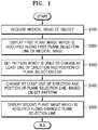
- FIG. 1 is a flowchart illustrating a method of changing at least one of a direction and position of a plane selection line, according to an embodiment of the present invention.
- a method of changing at least one of a direction and position of a plane selection line for acquiring an image of a POI of an object includes operation S100 of acquiring a medical image of an object, operation S200 of displaying a first plane image acquired along a first plane selection line of the medical image, operation S300 of setting a pattern which is used to change at least one of the direction and position of the plane selection line, operation S400 of changing at least one of the direction and position of the plane selection line, based on the set pattern, and operation S500 of displaying a second plane image acquired along the changed plane selection line.
- the plane selection line according to an embodiment of the present invention is automatically or manually selected based on an anatomical position of a part of interest, a measurement target item, and an anatomical view in the object.
- the direction or position of the plane selection line according to an embodiment of the present invention may be referred to as a geometry of the plane selection line.
- the method may receive an echo signal based on an ultrasound wave, which is transmitted from a probe of an ultrasound diagnostic apparatus to the object, to acquire an ultrasound image of the object.
- the ultrasound image may be at least one of a brightness (B) mode image, a color (C) mode image, a Doppler (D) mode image, but is not limited thereto.
- the medical image may include a two-dimensional (2D) image, a three-dimensional (3D) volume image, or a dynamic image.
- a plane image may be acquired from a rendered image (for example, a 3D volume image) which is obtained by using ultrasound 3D data, based on the plane selection line.
- the plane selection line may be expressed as a plane selection surface in a VCT mode of 3D data.
- Operation S200 of displaying the first plane image acquired along the first plane selection line of the medical image may include an operation of displaying the medical image and first plane image of the object.
- the medical image and first plane image of the object may be displayed in parallel.
- the displaying of the medical image and first plane image of the object in parallel denotes that the images may be arranged in a certain direction and displayed in parallel with each other.
- the certain direction may include at least one of an up direction, a down direction, a left direction, a right direction, and a diagonal direction.
- the pattern for changing at least one of the direction and position of the plane selection line may be previously set and stored in a storage device (not shown), or may be set (S300) based on an external input from a user.
- At least one of the direction and position of the plane selection line may be changed based on the set pattern in operation S400, and the second plane image acquired along the changed plane selection line may be displayed by a display in operation S500.
- the first and second plane images according to an embodiment of the present invention may be images that are acquired along the plane selection line, in a direction vertical to a medical image 210.
- x, y, and z may be coordinate values in a space where a 3D image is expressed and which is composed of an x axis, a y axis, and a z axis.
- the pattern for changing at least one of the direction and position of the plane selection line may be expressed as a 3x4 matrix as in Equation (2).
- a parallel movement of a line according to an embodiment of the present invention may be achieved by a parallel movement conversion of a point included in the line.
- a position of the line may be changed by changing the coordinate values (for example, x, y, and z) in the space composed of the x axis, the y axis, and the z axis with respect to the object as expressed in the following Equation (3): 1 0 0 tx 0 1 0 ty 0 0 1 tz 0 0 0 1
- a rotation movement of the line may be achieved by a rotation movement conversion of the point included in the line.
- a direction of the line may be changed by changing the coordinate values (for example, x, y, and z) in the space composed of the x axis, the y axis, and the z axis with respect to the object as expressed in the following Equation (4): cos ⁇ 0 sin ⁇ 0 0 1 0 0 ⁇ sin ⁇ 0 cos ⁇ 0 0 0 0 1
- a pattern for changing the line according to an embodiment of the present invention may be generated by a combination of a matrix of Equation (3) and a matrix of Equation (4).
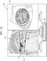
- FIGS. 2A and 2B illustrate an example of a method of determining an ROI and changing at least one of a direction and position of a plane selection line based on a pattern which is generated based on the determined ROI.
- the medical image 210 of an object may be acquired in operation S100.
- the medical image of a head of the fetus may be acquired, and displayed on a screen 200.
- a first plane image 220 acquired along a first plane selection line 212 in the medical image 210 may be displayed in operation S200.
- a user may perform various measurements depending on the kind of examination and an examination item for an object, for accurately performing a clinical determination of the object. It is important for the user to accurately find an ROI (for example, a POI), for accurately measuring an examination item (for example, bi-parietal diameter (BPD)) of the object. Therefore, the user may variously change at least one of a direction and position of a plane selection line to detect the POI.
- an ROI for example, a POI
- BPD bi-parietal diameter
- a pattern for detecting the POI is previously set, and the user may detect the POI by using the set pattern, thereby shortening a time taken in detecting the POI. Accordingly, an efficiency of a diagnosis by the user increases in comparison to that of the related art.
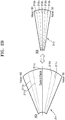
- Operation S300 of setting the pattern for changing at least one of the direction and position of the plane selection line may include an operation of determining an ROI 211 including a first-direction plane selection line 212 in the acquired medical image 210, an operation of generating at least one plane selection lines which have different directions or positions and are included in the determined ROI 211, an operation of extracting the generated at least one plane selection lines, and an operation of generating a pattern in order where the at least one plane selection lines are extracted.
- the ROI 211 may have a fan shape in a width-direction.
- the ROI 211 may be determined as a region which is unfolded at a certain angle within a certain range with respect to the first-direction plane selection line 212.
- the certain angle and the certain range may be previously determined based on at least one of the kind of examination and an examination item for the object. Also, the certain angle and the certain range may be set and adjusted according to an external input from the user.
- At least one plane selection lines 211a to 211e which have different directions or positions and are included in the ROI 211 may be generated. Also, the generated at least one plane selection lines 211a to 211e may be extracted one by one. A pattern for changing at least one of a direction and position of a plane selection line may be generated in order where the at least one plane selection lines 211a to 211e are extracted. For example, a plane may be extracted in the order of the plane selection line 211c, plane selection line 211b, plane selection line 211d, plane selection line 211a, and plane selection line 211e.
- the first-direction plane selection line 212 may be the plane selection line 211c, and hereinafter, may be referred to as a line indicating a currently displayed surface or plane 220. Since the plane may be extracted in the order of the plane selection line 211c, plane selection line 211b, plane selection line 211d, plane selection line 211a, and plane selection line 211e, a plane selection line may be changed in the order of the plane selection line 211c, plane selection line 211b, plane selection line 211d, plane selection line 211a, and plane selection line 211e. In the plane selection lines 211a to 211e, at least one of directions and positions may differ.
- At least one generated plane selection line may be removed based on an external input signal.
- the plane selection line 211a or the plane selection line 211e may be removed from the ROI 211 according to a line removal signal which is input from the outside by the user.
- a plane selection line may be changed in the order of the plane selection line 211c, plane selection line 211b, and plane selection line 211d.
- Operation S300 of setting the pattern for changing at least one of the direction and position of the plane selection line may further include an operation of re-determining an ROI, an operation of regenerating at least one plane selection lines which have different directions or positions and are included in the re-determined ROI, an operation of re-extracting the regenerated at least one plane selection lines, and an operation of regenerating the pattern in order where the at least one plane selection lines are re-extracted.
- An interval between the at least one plane selection lines when a plane selection line is regenerated may be denser than an interval of when the plane selection line is generated.
- the ROI 211 may be re-determined as a new ROI 213.
- a pattern for changing at least one of a direction and position of a plane selection line may be more minutely generated than a pattern which is generated based on an ROI (for example, 211).
- an interval between the regenerated at least one plane selection lines 213a to 213e may be denser than the interval between the plane selection lines 211a to 211e which are generated to be included in the ROI 211.
- the user may re-determine the new ROI 213 by narrowing the ROI 211 which was previously determined, thereby allowing a more precise selection of a plane of the object and allowing a pattern, which is used to change at least one of a direction and position of a plane selection line, to be more minutely generated.
- At least one of the direction and position of the plane selection line may be changed based on the set pattern in operation S400, and the second plane image acquired along the changed plane selection line may be displayed by a display in operation S500.
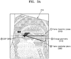
- FIGS. 3A and 3B illustrate an example of a method of changing at least one of a direction and position of a plane selection line based on a generated pattern, according to an embodiment of the present invention.
- Operation S300 of setting the pattern for changing at least one of the direction and position of the plane selection line includes an operation of extracting the first plane selection line, for a first standard image to be acquired as the first plane image, an operation of extracting a reference region from the acquired medical image and may include an operation of rotating the extracted first plane selection line by a certain angle based on the reference region to change the extracted first plane selection line to a second plane selection line, and an operation of generating, as a pattern, a rotation movement from the first plane selection line to the second plane selection line.
- a change pattern may be generated by using anatomical information of an object.
- a first plane selection line 310 may be extracted from a medical image 210 in order for the first standard image to be acquired as the first plane image.
- the first standard image may be referred to as a first standard view.
- the first standard image may be an image indicating mid-sagittal plane, transventricle plane, transthalamic plane, and transcerebellar plane.
- the first standard image may include four chamber views, five chamber views, three vessel views, RVOT, LVOT, a bicaval view, aortic arch, ductral arch, a high short axis view, and a low short axis view.
- the first standard image may be an image may include a plane (or a view) for abdominal circumference (AC) measurement, a plane (or a view) for head circumference (HC) measurement, and a plane (or a view) for crown-rump length (CRL) measurement.
- AC abdominal circumference
- HC head circumference
- CTL crown-rump length
- a reference region 320 may be extracted from the acquired medical image 210.
- the reference region 320 is a position or a region which includes a unique tissue in the object, and may be referred to as a landmark.
- the reference region 320 may include a cavum septum pellucidum (CSP).
- CSP cavum septum pellucidum
- by changing the extracted first plane selection line 310 by a certain angle based on the reference region 320 the first plane selection line 310 may be changed to a second plane selection line 330.
- the second plane selection line 330 may be a line from which a trans-cerebellar plane is acquired.
- a rotation movement from the first plane selection line 310 to the second plane selection line 330 may be generated as a pattern.
- a first plane selection line for example, a line from which a trans-thalamic plane is acquired
- a reference region for example, CSP
- the extracted first plane selection line may be rotated and moved with respect to the reference region, thereby generating a pattern in which the first plane selection line is changed to a second plane selection line (for example, a line from which a trans-cerebellar plane is acquired).
- a pattern may be generated based on a relationship (for example, a rotation movement of a certain angle) between a reference region, referred to as a landmark, and various views (for example, a first plane based on a first plane selection line and a second plane based on a second plane selection line).
- a plane selection line may be changed through a rotation movement from a start line 311 to an end line 331 according to a pattern in which the first plane selection line is set as a start line 311 and the second plane selection line is set as an end line 331 for changing a pattern, and thus, a plane 220 based on each line may be displayed.
- FIGS. 4A to 4D illustrate an example of a generated pattern according to an embodiment of the present invention.
- FIG. 4A illustrates an example of a generated basic change pattern according to an embodiment of the present invention.
- Operation S300 of setting the pattern for changing at least one of the direction and position of the plane selection line may include an operation of generating at least one plane selection lines adjacent to the first plane selection line, an operation of extracting the generated at least one plane selection lines, and an operation of generating a pattern for changing a line in order where the at least one plane selection lines are extracted.
- At least one plane selection lines 421a to 426a may be generated adjacent to upper and lower positions with respect to a first plane selection line 410a that is a current line.
- the generated at least one plane selection lines 421a to 426a may be extracted sequentially or randomly from an upper end (or a lower end).
- lines may be extracted in the order of the plane selection line 421a, plane selection line 422a, and plane selection line 423a.
- lines may be randomly extracted, for example, in the order of the plane selection line 421a, plane selection line 425a, and plane selection line 423a.
- a pattern for changing a line may be generated in order where lines are extracted. In other words, a line may be moved or changed from a first plane selection line to at least one plane selection line disposed adjacent to the first plane selection line, and thus, a user may acquire a POI.
- Operation S300 of setting the pattern for changing at least one of the direction and position of the plane selection line may include an operation of extracting the first plane selection line, for a first standard image to be acquired as the first plane image, an operation of generating at least one plane selection lines which are moved and disposed in a certain direction from the extracted first plane selection line, an operation of extracting the generated at least one plane selection lines, and an operation of generating a pattern for changing a line in order where the at least one plane selection lines are extracted.
- the certain direction may include at least one of an up direction, a down direction, a left direction, a right direction, and a diagonal direction.
- a first plane selection line 430, from which the first standard image is acquired, may be referred to as a standard view line.
- the first standard image may include a mid-sagittal image or a trans-thalamic image.
- the first plane selection line 430 for acquiring the first standard image is extracted, at least one plane selection lines 421b to 426b which are disposed to be spaced apart from the extracted first plane selection line 430 in a certain direction may be generated.
- the at least one plane selection lines 421b to 426b which are disposed to be spaced apart from the first plane selection line 430 by a certain interval in a down direction may be generated.
- the certain interval may be an interval equal to a height of one pixel or two pixels.
- the at least one plane selection lines 421b to 426b which are generated in a certain direction (for example, a down direction) from the first plane selection line 430 may be extracted sequentially or randomly.
- lines may be extracted in the order of the plane selection line 421b, plane selection line 422b, and plane selection line 423b.
- lines may be randomly extracted, for example, in the order of the plane selection line 421b, plane selection line 425b, and plane selection line 423b.
- a pattern for changing a line may be generated in order where the at least one plane selection lines 421b to 426b are extracted.
- Operation S300 of setting the pattern for changing at least one of the direction and position of the plane selection line may include an operation of extracting a reference region from the acquired medical image, an operation of generating at least one plane selection lines which pass through the reference region and are within a certain angle range, an operation of extracting the generated at least one plane selection lines, and an operation of generating a pattern for changing a line in order where the at least one plane selection lines are rotated with respect to the reference region and extracted.
- a reference region 320 may be extracted from the medical image of the object.
- the reference region 320 is a position or a region which includes a unique tissue in the object, and may be referred to as a landmark.
- the reference region 320 may include a CSP or a thalamus of a diencephalon.
- At least one plane selection lines 421c to 427c which pass through the extracted reference region 320 and are within a certain angle range, may be generated.
- the generated at least one plane selection lines 421c to 427c may be rotated with respect to the reference region 320 and extracted sequentially or randomly.
- a pattern for changing a line may be generated in order where the at least one plane selection lines 421c to 427c are extracted.
- At least one plane selection lines 421d to 425d may be generated by rotating and moving a line 410 indicating a current plane (for example, 220 in FIG. 2A or 3B ) by a certain angle based on a first plane selection line 430 (from which a first standard image is acquired) and a reference region 320 of an object.
- the generated at least one plane selection lines 421d to 425d may be extracted sequentially or randomly, and a pattern for changing a line may be generated in order where the plane selection lines 421d to 425d are extracted.
- a line change pattern may be set in order for a line to be changed depending on the at least one plane selection lines (for example, 211a to 211e or 213a to 213e) generated in the ROI 211 or 213.
- the ROI 211 or 213 may be a region within a range having a high probability that includes a standard plane image acquirable in a position or a direction which is recommended by an international organization.
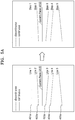
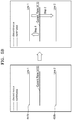
- FIGS. 5A to 5D illustrate an example of a generated pattern according to another embodiment not forming part of the present invention.
- Operation S300 of setting the pattern for changing at least one of the direction and position of the plane selection line may include an operation of generating at least one plane selection lines in order where an external input signal is applied, an operation of extracting the at least one plane selection lines in order where the at least one plane selection lines are generated, and an operation of generating a pattern for changing a line in order where the at least one plane selection lines are extracted.
- At least one plane selection lines 451a to 455a may be generated based on an external input signal from a user.
- the at least one plane selection lines 451a to 455a may be generated in order where the external input signal is applied to the ultrasound diagnostic apparatus for generating a line.
- a user may input the external input signal to the ultrasound diagnostic apparatus by using a cursor having an arrow shape or a linear-direction touch in a touch screen.
- a plane selection line may be extracted according to a generated order.
- lines may be generated in the order of a line 451a, a line 452a, a line 453a, a line 454a, and a line 455a
- a plane selection line may be extracted according to the generated order.
- a pattern for example, step 1 to step 5 in FIG. 5A
- a line for example, an order of from 451a to 455a
- the pattern for changing the line may be generated as a pattern in which lines are discontinuously moved in the order of the line 451a, line 452a, line 453a, line 454a, and line 455a from a line 410 indicating a current plane image and thus are changed.
- Operation S300 of setting the pattern for changing at least one of the direction and position of the plane selection line may include an operation of generating a second plane selection line adjacent to the first plane selection line, based on an external input signal, an operation of generating at least one plane selection lines which are provided between the first and second plane selection lines, an operation of sequentially extracting at least one plane selection lines, which are provided between the first and second selection lines, while moving lines in a certain direction from the first plane selection line to the second plane selection line, and an operation of generating a pattern for changing a line in order where the at least one plane selection lines are extracted.
- the certain direction may include at least one of an up direction, a down direction, a left direction, a right direction, and a diagonal direction.
- a second plane selection line adjacent to a first plane selection line may be generated based on an external input signal.
- the first plane selection line may be a line 410 from which a current plane image is acquired.
- at least one plane selection lines (not shown) which are provided between a first plane selection line 410 and a second plane selection line 451b may be generated.
- the at least one plane selection lines which are provided between the first plane selection line 410 and the second plane selection line 451b and moved in a certain direction from the first plane selection line 410 to the second plane selection line 451b may be sequentially extracted.
- a pattern for changing a line may be generated in order where the at least one plane selection lines are extracted.
- At least one plane selection lines (not shown) which have a certain thickness and are provided between the first plane selection line 410 and the second plane selection line 451b may be generated.
- the certain thickness may be the same as that of the first plane selection line 410 or second plane selection line 451b.
- the at least one plane selection lines which are provided between the first plane selection line 410 and the second plane selection line 451b and moved in an up direction from the first plane selection line 410 to the second plane selection line 451b may be sequentially extracted, and a pattern for changing a line may be generated in order where the at least one plane selection lines are extracted. Therefore, the pattern for changing the line may be set to be changed depending on all plane selection lines which are provided between the first plane selection line 410 and the second plane selection line 451b.
- the at least one plane selection lines which are provided between the first plane selection line 410 and the second plane selection line 451b and moved from the first plane selection line 410 (which is a line from which a current plane image is acquired) to the second plane selection line 451b may be continuously extracted, and a pattern for changing a line may be generated in order where the at least one plane selection lines are extracted.
- a portion (for example, step 1 in FIG. 5B ) of a pattern for changing a line may be generated in order where all lines (not shown), which are provided between the first plane selection line 410 and the second plane selection line 451b and moved in an up direction from the first plane selection line 410 to the second plane selection line 451b, are extracted.
- a portion (for example, step 2 in FIG. 5B ) of the pattern for changing the line may be generated in order where all lines (not shown), which are provided between the second plane selection line 451b and a third plane selection line 452b and moved in a down direction from the second plane selection line 451b to the third plane selection line 452b, are extracted.
- a pattern (including the portion (for example, step 1 or step 2 in FIG. 5B ) of the pattern described above with reference to FIG. 5B ) for changing a line may be generated.
- the pattern for changing the line may be generated by combining step 1 and step 2 of FIG. 5B .
- a second plane selection line which is disposed adjacent to a first plane selection line in a certain direction may be generated based on an external input signal.
- the first plane selection line may be a line 410 from which a current plane image is acquired.
- at least one plane selection lines (not shown) provided between a first plane selection line 410 and a second plane selection line 451c may be generated.
- At least one plane selection lines which are provided between the first plane selection line 410 and the second plane selection line 451c and are rotated and moved by a certain angle to the second plane selection line 451c with respect to the first plane selection line 410 may be sequentially extracted, and a pattern for changing a line may be generated in order where the at least one plane selection lines are extracted.
- a pattern for changing a line may be set to be changed along all plane selection lines which are provided between the first plane selection line 410 and the second plane selection line 451c.
- at least one plane selection lines which are provided between the first plane selection line 410 and the second plane selection line 451c and are rotated and moved by a certain angle " ⁇ 1 " from the first plane selection line 410 to the second plane selection line 451c may be continuously extracted, and a portion (step 1) of a pattern for changing a line may be generated in order where the at least one plane selection lines are extracted.
- At least one plane selection lines which are provided between the second plane selection line 451c and a third plane selection line 452c and are rotated and moved by a certain angle " ⁇ 2 " from the second plane selection line 451c to the third plane selection line 452c may be continuously extracted, and a portion (step 2) of a pattern for changing a line may be generated in order where the at least one plane selection lines are extracted.
- a pattern including the portion (for example, step 1 or step 2 in FIG. 5C ) of the pattern described above with reference to FIG. 5C ) for changing a line may be generated. In other words, the pattern for changing the line may be generated by combining step 1 and step 2 of FIG. 5C .
- a pattern may be generated by combining the above-described methods of changing a line.
- a pattern in which a line is discontinuously moved (for example, step 1) from the first plane selection line 410 (which is a line from which a current plane image is acquired) to a line 451d, a line is continuously moved (for example, step 2) from the line 451d to a line 452d, a line is rotated and moved by a certain angle " ⁇ 3 " from the line 452d to a line 453d, and a line is discontinuously moved (step 4 and step 5) to a line 454d and a line 455d may be generated as a pattern for changing a line.
- Operation S300 of setting the pattern for changing at least one of the direction and position of the plane selection line may include an operation of loading a pattern which is predetermined and is previously stored in a storage device (not shown), and setting a pattern, based on the loaded pattern.
- a pattern which is predetermined and is previously stored in a storage device may be loaded, and the loaded pattern may be set as a pattern for changing at least one of a direction and position of a plane selection line.
- the loaded pattern may be edited by the above-described method, and may be set as a pattern for changing at least one of a direction and position of a plane selection line.
- Operation S400 of changing at least one of the direction and position of the plane selection line based on the set pattern may include an operation of changing at least one of the direction and position of the plane selection line based on the set pattern automatically or according to an external input,.
- At least one from among the direction and position of the plane selection line may be automatically changed based on the set pattern.
- at least one from among the direction and position of the plane selection line may be automatically changed based on the set pattern in operation S400, and the second plane image acquired along the changed plane selection line may be displayed by a display in operation S500.
- an orientation adjusting unit (for example, 230 in FIG. 2A ) may be adjusted according to an external input, and at least one from among a direction and position of a plane selection line may be easily changed based on a pattern.
- an up, down, left, and right rotation movement of a 3D image of an object are performed on an x axis, a y axis, and a z axis a plurality of times, for acquiring a POI.
- the orientation adjusting unit (for example, 230 in FIG.
- the orientation adjusting unit may be, for example, a controller including a bar and a rotation button as in 230 of FIG. 2A .
- Operation S400 of changing at least one from among the direction and position of the plane selection line based on the set pattern may further include an operation of tracing at least one from among the direction and position of the plane selection line which are changed based on the set pattern and an operation of displaying a result of the tracing as a time-series image.
- a pattern (which is generated by the above-described method) for changing a line may be displayed as a time-series image.
- a user may analyze the pattern displayed as the time-series image, and correct the pattern by adding or deleting a line.
- a trace result of a pattern for changing a line may be displayed as a time-series image, and thus, it is easy to analyze an anatomical structure of an object.
- a plane image based on lines adjacent to a line from which a current plane is acquired may be displayed in time series, and thus, a longest region or largest region of an object may be detected.
- Vp is clearly included in a currently displayed plane image (for example, 220) and whether Vp is the largest shown.
- TCD is clearly included in a currently displayed plane image (for example, 220) and whether TCD is the largest shown.
- FIGS. 6A and 6B illustrate an example of a method of changing a plane selection line based on an external input, not forming part of the present invention.
- the method may further include an operation of selecting a first point from an acquired medical image according to a first external input and selecting a second point according to a second external input, an operation of generating a first plane selection line including the selected first and second points, and an operation of displaying information about a pattern which is set for changing at least one from among a direction and position of a plane selection line by the above-described method.
- the first plane selection line may be moved according to a third external input in the acquired medical image, based on the displayed information, and a plane image may be acquired along the moved first plane selection line.
- a first point 611 may be selected from a medical image 210 according to a first external input 610
- a second point 621 may be selected according to a second external input 620.
- the first and second external inputs 610 and 620 may include a click input using a cursor or a touch input on a touch screen.
- a first plane selection line 410 including the selected first and second points 611 and 621 may be generated.
- information about a pattern which is set for changing at least one from among a direction and position of the generated first plane selection line 410 by the above-described method may be displayed.
- a user may change at least one from among the direction and position of the first plane selection line 410 by using a third input 630 with reference to the displayed information about the pattern for changing a line.
- the third input 630 may include a drag for the first plane selection line 410.
- a first point 613 may be selected from a medical image 210 according to a first external input 610, and a second point 623 may be selected according to a second external input 620.
- the first and second external inputs 610 and 620 may include a click input using a cursor or an input corresponding to a touch of a touch screen.
- the first point 613 which is selected according to the first external input 610 may be a point which is the closest to a point to which the first external input 610 is applied.
- a point corresponding to a predetermined position may be selected.
- the point corresponding to the predetermined position may include a point in a first plane selection line 410 which is to be generated based on a pattern which is set by the above-described method.
- the first plane selection line 410 including the selected first and second points 611 and 621 may be generated. Also, information about a pattern which is set for changing at least one from among a direction and position of the generated first plane selection line 410 by the above-described method may be displayed. The user may change at least one from among the direction and position of the first plane selection line 410 by using a third input 630 with reference to the displayed information about the pattern for changing a line.
- the third input 630 may include a drag for the first plane selection line 410.
- FIG. 7 is a block diagram illustrating an apparatus 700 for changing at least one from among a direction and position of a plane selection line, according to an embodiment of the present invention.
- the apparatus 700 for changing at least one from among a direction and position of a plane selection line includes a medical image acquiring unit 710 that acquires a medical image of an object, a display 720 that displays a first plane image acquired along a first plane selection line of the medical image, a pattern setting device 730 that setting a pattern which is used to change at least one from among the direction and position of the plane selection line, and a line changing device 740 that changes at least one from among the direction and position of the plane selection line, based on the set pattern.
- the display displays a second plane image acquired along the changed plane selection line.
- the plane selection line according to an embodiment of the present invention may be automatically or manually selected based on an anatomical position of a part of interest, a measurement target item, and an anatomical view in the object.
- the medical image may include a 2D image, a 3D volume image, or a dynamic image.
- the display 720 may display the medical image and first plane image of the object.
- the pattern setting device 730 may determine an ROI including a first-direction plane selection line in the acquired medical image, generate at least one plane selection lines which have different directions or positions and are included in the determined ROI, extract the generated at least one plane selection lines, and generate the pattern in order where the at least one plane selection lines are extracted.
- the generated at least one plane selection lines may be removed according to an external input from a user.
- the ROI 211 may have a width-direction fan shape.
- the ROI 211 may be determined as a region which is unfolded at a certain angle within a certain range with respect to the first-direction plane selection line 212.
- the certain angle and the certain range may be previously determined based on at least one from among the kind of examination and an examination item for the object.
- the certain angle and the certain range may be set and adjusted according to an external input from the user.
- the pattern setting device 730 may re-determine an ROI, regenerate at least one plane selection lines which have different directions or positions and are included in the re-determined ROI, re-extract the regenerated at least one plane selection lines, and regenerate the pattern in order where the at least one plane selection lines are re-extracted.
- An interval between the at least one plane selection lines when a plane selection line is regenerated may be denser than an interval of when the plane selection line is generated.
- the pattern setting device 730 may extract the first plane selection line, for a first standard image to be acquired as the first plane image, extract a reference region from the acquired medical image, rotate the extracted first plane selection line by a certain angle based on the reference region to change the extracted first plane selection line to a second plane selection line, and generate, as the pattern, a rotation movement from the first plane selection line to the second plane selection line.
- the pattern setting device 730 may generate at least one plane selection lines adjacent to the first plane selection line, extract the generated at least one plane selection lines, and generate the pattern in order where the at least one plane selection lines are extracted.
- the pattern setting device 730 may extract the first plane selection line, for a first standard image to be acquired as the first plane image, generate at least one plane selection lines which are moved and disposed in a certain direction from the extracted first plane selection line, extract the generated at least one plane selection lines, and generate the pattern in order where the at least one plane selection lines are extracted.
- the certain direction may include at least one from among an up direction, a down direction, a left direction, a right direction, and a diagonal direction.
- the pattern setting device 730 may extract a reference region from the acquired medical image, generate at least one plane selection lines which pass through the reference region and are within a certain angle range, extract the generated at least one plane selection lines, and generate the pattern in order where the at least one plane selection lines are rotated with respect to the reference region and extracted.
- the apparatus 700 may further include an external input receiving unit 750.
- the pattern setting device 730 may generate at least one plane selection lines in order where an external input signal is applied, extract the at least one plane selection lines in order where the at least one plane selection lines are generated, and generate the pattern in order where the at least one plane selection lines are extracted.
- the pattern setting device 730 may generate a second plane selection line adjacent to the first plane selection line, based on an external input signal, generate at least one plane selection lines which are provided between the first and second plane selection lines, sequentially extract at least one plane selection lines which are provided between the first and second selection lines, while moving lines in a certain direction from the first plane selection line to the second plane selection line, and generate a pattern for changing a line in order where the at least one plane selection lines are extracted.
- the certain direction may include at least one from among an up direction, a down direction, a left direction, a right direction, and a diagonal direction.
- the pattern setting device 730 may load a pattern which is predetermined and is previously stored in a storage device, and set a pattern for changing at least one from among the direction and position of the plane selection line, based on the loaded pattern.
- the storage device may be included in the apparatus 700 according to an embodiment of the present invention, or may be provided in the outside and connected to the apparatus 700.
- the storage device may be connected to the pattern setting device 730.
- a pattern which is predetermined and is previously stored in a storage device may be loaded, and the loaded pattern may be set as a pattern for changing at least one from among a direction and position of a plane selection line.
- the loaded pattern may be edited by the above-described method, and may be set as a pattern for changing at least one from among a direction and position of a plane selection line.
- the line changing device 740 may change at least one from among the direction and position of the plane selection line based on the set pattern automatically or according to an external input.
- the line changing device 740 may trace at least one from among the direction and position of the plane selection line which is changed based on the set pattern, and the display 720 may display a result of the tracing as a time-series image.
- the pattern setting device 730 may select a first point from the acquired medical image according to a first external input, select a second point according to a second external input, generate a first plane selection line including the selected first and second points, and display information about a pattern which is set for changing at least one from among the direction and position of the plane selection line.
- the first plane selection line may be moved according to a third external input in the acquired medical image, based on the displayed information, and a plane image may be acquired along the moved first plane selection line.
- Examples of the computer-readable recording medium include magnetic storage media (e.g., ROM, floppy disks, hard disks, etc.) and optical recording media (e.g., CD-ROMs, or DVDs), etc).
- magnetic storage media e.g., ROM, floppy disks, hard disks, etc.
- optical recording media e.g., CD-ROMs, or DVDs
Landscapes
- Health & Medical Sciences (AREA)
- Life Sciences & Earth Sciences (AREA)
- Engineering & Computer Science (AREA)
- Physics & Mathematics (AREA)
- Medical Informatics (AREA)
- General Health & Medical Sciences (AREA)
- Nuclear Medicine, Radiotherapy & Molecular Imaging (AREA)
- Radiology & Medical Imaging (AREA)
- Surgery (AREA)
- Biomedical Technology (AREA)
- Molecular Biology (AREA)
- Pathology (AREA)
- Animal Behavior & Ethology (AREA)
- Biophysics (AREA)
- Public Health (AREA)
- Veterinary Medicine (AREA)
- Heart & Thoracic Surgery (AREA)
- Computer Vision & Pattern Recognition (AREA)
- Computer Graphics (AREA)
- General Engineering & Computer Science (AREA)
- General Physics & Mathematics (AREA)
- Theoretical Computer Science (AREA)
- Quality & Reliability (AREA)
- Ultra Sonic Daignosis Equipment (AREA)
- Magnetic Resonance Imaging Apparatus (AREA)
- Apparatus For Radiation Diagnosis (AREA)
- Image Analysis (AREA)
Claims (6)
- Procédé de modification d'au moins une parmi une direction et une position d'une ligne de sélection de plan pour acquérir une image d'un plan d'intérêt (POI) d'un objet, le procédé comprenant :l'acquisition d'une image médicale (210) d'un objet ;l'affichage d'une première image de plan (220) acquise le long d'une première ligne de sélection de plan (212) de l'image médicale (210) ;la définition d'un motif qui est utilisé pour modifier au moins l'une de la direction et de la position de la ligne de sélection de plan ;la modification d'au moins l'une de la direction et de la position de la ligne de sélection de plan, sur la base du motif défini ; etl'affichage d'une seconde image de plan acquise le long de la ligne de sélection de plan modifiée,dans lequel la ligne de sélection de plan est sélectionnée automatiquement ou manuellement sur la base d'une position anatomique d'une partie d'intérêt, d'un élément cible de mesure, et d'une vue anatomique dans l'objet,dans lequel la définition du motif comprend :l'extraction de la première ligne de sélection de plan (212), pour une première image standard à acquérir en tant que première image de plan (220) et les étapes (a-c) de :a) l'extraction d'une région de référence à partir de l'image médicale acquise (210) ;b) la rotation de la première ligne de sélection de plan extraite (212) d'un certain angle sur la base de la région de référence afin de modifier la première ligne de sélection de plan extraite (212) en une seconde ligne de sélection de plan ; etc) la génération, en tant que motif, d'un mouvement de rotation de la première ligne de sélection de plan (212) à la seconde ligne de sélection de plan,ou les étapes (d-g) de :d) la génération d'au moins une seconde ligne de sélection de plan qui est déplacée et disposée dans une certaine direction à partir de la première ligne de sélection de plan extraite (212) ;e) l'extraction de ladite au moins une seconde ligne de sélection de plan générée ; etf) la génération du motif dans un ordre où ladite au moins une seconde ligne de sélection de plan est extraite,g) dans lequel ladite certaine direction comprend au moins l'une d'une direction vers le haut, une direction vers le bas, une direction vers la gauche, une direction vers la droite, et une direction diagonale.
- Procédé selon la revendication 1, dans lequel l'image médicale (210) comprend une image bidimensionnelle (2D), une image de volume tridimensionnelle (3D), ou une image dynamique.
- Procédé selon la revendication 1, dans lequel l'affichage de la première image de plan (220) comprend l'affichage à la fois de l'image médicale (210) de l'objet et de la première image de plan (220) de l'objet.
- Procédé selon la revendication 1, dans lequel la modification d'au moins l'une de la direction et de la position de la ligne de sélection de plan comprend la modification d'au moins l'une de la direction et de la position de la ligne de sélection de plan sur la base du motif défini automatiquement ou selon une entrée externe.
- Procédé selon la revendication 1, dans lequel la modification d'au moins l'une de la direction et de la position de la ligne de sélection de plan comprend :le traçage d'au moins l'une de la direction et de la position de la ligne de sélection de plan qui est modifiée sur la base du motif défini ; etl'affichage du résultat de traçage sous forme d'image de série chronologique.
- Appareil (700) pour modifier au moins l'une d'une direction et d'une position d'une ligne de sélection de plan pour acquérir une image d'un plan d'intérêt (POI) d'un objet, l'appareil comprenant :un dispositif d'acquisition d'images médicales (710) configuré pour acquérir une image médicale d'un objet ;un écran (720) configuré pour afficher une première image de plan (220) acquise le long d'une première ligne de sélection de plan (212) de l'image médicale (210) ;un dispositif de définition de motif (730) configuré pour définir un motif qui est utilisé pour modifier au moins l'une de la direction et de la position de la ligne de sélection de plan ; etun dispositif de modification de ligne (740) configuré pour modifier au moins l'une de la direction et de la position de la ligne de sélection de plan, sur la base du motif défini,dans lequel,l'écran (720) configuré pour afficher une seconde image de plan acquise le long de la ligne de sélection de plan modifiée, etla ligne de sélection de plan est sélectionnée automatiquement ou manuellement sur la base d'une position anatomique d'une partie d'intérêt, d'un élément cible de mesure, et d'une vue anatomique dans l'objet,dans lequel le dispositif de définition de motif (730) est en outre configuré pourextraire la première ligne de sélection de plan (212), pour une première image standard à acquérir en tant que première image de plan (220) et a) - c) de :a) l'extraction d'une région de référence à partir de l'image médicale acquise (210) ;b) la rotation de la première ligne de sélection de plan extraite (212) d'un certain angle sur la base de la région de référence afin de modifier la première ligne de sélection de plan extraite (212) en une seconde ligne de sélection de plan ; etc) la génération, en tant que motif, d'un mouvement de rotation de la première ligne de sélection de plan (212) à la seconde ligne de sélection de plan,ou d) - g) de :d) la génération d'au moins une seconde ligne de sélection de plan qui est déplacée et disposée dans une certaine direction à partir de la première ligne de sélection de plan extraite (212) ;e) l'extraction de ladite au moins une seconde ligne de sélection de plan générée ; etf) la génération du motif dans un ordre où ladite au moins une seconde ligne de sélection de plan est extraite,g) dans lequel ladite certaine direction comprend au moins l'une d'une direction vers le haut, une direction vers le bas, une direction vers la gauche, une direction vers la droite, et une direction diagonale.
Applications Claiming Priority (1)
| Application Number | Priority Date | Filing Date | Title |
|---|---|---|---|
| KR1020140031159A KR102245202B1 (ko) | 2014-03-17 | 2014-03-17 | 단면 선택 라인의 방향 및 위치 중 적어도 하나를 소정의 패턴에 따라 변경하기 위한 방법 및 장치 |
Publications (2)
| Publication Number | Publication Date |
|---|---|
| EP2921114A1 EP2921114A1 (fr) | 2015-09-23 |
| EP2921114B1 true EP2921114B1 (fr) | 2020-06-17 |
Family
ID=52023319
Family Applications (1)
| Application Number | Title | Priority Date | Filing Date |
|---|---|---|---|
| EP14197361.0A Active EP2921114B1 (fr) | 2014-03-17 | 2014-12-11 | Procédé et appareil permettant de modifier une direction ou position d'une ligne de sélection de plan sur la base d'un motif |
Country Status (4)
| Country | Link |
|---|---|
| US (1) | US9747686B2 (fr) |
| EP (1) | EP2921114B1 (fr) |
| KR (1) | KR102245202B1 (fr) |
| CN (1) | CN104921752B (fr) |
Families Citing this family (5)
| Publication number | Priority date | Publication date | Assignee | Title |
|---|---|---|---|---|
| KR102531117B1 (ko) * | 2015-10-07 | 2023-05-10 | 삼성메디슨 주식회사 | 대상체를 나타내는 영상을 디스플레이하는 방법 및 장치. |
| CN110072468B (zh) * | 2016-12-19 | 2022-11-18 | 皇家飞利浦有限公司 | 胎儿超声成像 |
| US12329580B2 (en) | 2020-03-05 | 2025-06-17 | Koninklijke Philips N.V. | Contextual multiplanar reconstruction of three-dimensional ultrasound imaging data and associated devices, systems, and methods |
| WO2021175629A1 (fr) * | 2020-03-05 | 2021-09-10 | Koninklijke Philips N.V. | Reconstruction multiplanaire contextuelle de données d'imagerie ultrasonores tridimensionnelles et dispositifs, systèmes et méthodes associés |
| DE102023116736A1 (de) * | 2022-06-30 | 2024-01-04 | Koninklijke Philips N.V. | Verarbeitung von ultraschallabtastdaten |
Family Cites Families (12)
| Publication number | Priority date | Publication date | Assignee | Title |
|---|---|---|---|---|
| JP2884218B2 (ja) | 1994-09-27 | 1999-04-19 | 松下電工株式会社 | 超音波センサーシステム |
| US20050049494A1 (en) * | 2003-08-29 | 2005-03-03 | Arthur Gritzky | Method and apparatus for presenting multiple enhanced images |
| JP5148057B2 (ja) | 2004-10-19 | 2013-02-20 | 株式会社東芝 | 超音波診断装置 |
| US7883467B2 (en) | 2004-10-19 | 2011-02-08 | Kabushiki Kaisha Toshiba | Ultrasonic diagnostic apparatus |
| JP5091556B2 (ja) | 2007-06-22 | 2012-12-05 | 株式会社東芝 | 超音波診断装置及び超音波画像生成方法 |
| KR100978479B1 (ko) | 2008-11-03 | 2010-08-30 | 주식회사 메디슨 | 스캔 변환을 고속으로 수행하는 초음파 시스템 및 방법 |
| KR101183767B1 (ko) | 2009-12-15 | 2012-09-17 | 삼성메디슨 주식회사 | 삼차원 초음파 이미지로부터 이차원 슬라이스 이미지를 선택하는 초음파 시스템 및 그 방법 |
| EP2335596A1 (fr) * | 2009-12-15 | 2011-06-22 | Medison Co., Ltd. | Système à ultrasons et procédé de sélection d'image en coupe à partir d'une image ultrasonore tridimensionnelle |
| JP5606076B2 (ja) * | 2010-01-08 | 2014-10-15 | 株式会社東芝 | 超音波診断装置、医用画像処理装置及び医用画像処理プログラム |
| JP5631629B2 (ja) * | 2010-05-17 | 2014-11-26 | 株式会社東芝 | 超音波画像処理装置及び超音波診断装置 |
| US9107607B2 (en) * | 2011-01-07 | 2015-08-18 | General Electric Company | Method and system for measuring dimensions in volumetric ultrasound data |
| KR20140024190A (ko) * | 2012-08-20 | 2014-02-28 | 삼성메디슨 주식회사 | 초음파 영상 관리 방법, 표시 방법 및 그 장치 |
-
2014
- 2014-03-17 KR KR1020140031159A patent/KR102245202B1/ko active Active
- 2014-12-11 EP EP14197361.0A patent/EP2921114B1/fr active Active
-
2015
- 2015-01-07 US US14/591,799 patent/US9747686B2/en active Active
- 2015-03-17 CN CN201510117073.3A patent/CN104921752B/zh active Active
Non-Patent Citations (1)
| Title |
|---|
| None * |
Also Published As
| Publication number | Publication date |
|---|---|
| CN104921752B (zh) | 2020-02-28 |
| KR20150108226A (ko) | 2015-09-25 |
| KR102245202B1 (ko) | 2021-04-28 |
| US20150262353A1 (en) | 2015-09-17 |
| US9747686B2 (en) | 2017-08-29 |
| EP2921114A1 (fr) | 2015-09-23 |
| CN104921752A (zh) | 2015-09-23 |
Similar Documents
| Publication | Publication Date | Title |
|---|---|---|
| US12029615B2 (en) | Ultrasound diagnosis apparatus and method for generating image from volume data and displaying the same | |
| US12496038B2 (en) | Image-based diagnostic systems | |
| EP2700364B1 (fr) | Procédé et appareil de gestion et d'affichage d'image ultrasonore | |
| US20210089812A1 (en) | Medical Imaging Device and Image Processing Method | |
| EP2916285B1 (fr) | Appareil de traitement d'image médicale et procédé de traitement d'image médicale en utilisant l'appareil | |
| EP2921114B1 (fr) | Procédé et appareil permettant de modifier une direction ou position d'une ligne de sélection de plan sur la base d'un motif | |
| US10192337B2 (en) | Method and apparatus for displaying an additional information related to measured value of object | |
| EP2989987B1 (fr) | Appareil de diagnostic à ultrasons et procédé et support de stockage lisible par ordinateur | |
| KR20250145102A (ko) | 초음파 이미지의 사용자 지원 획득을 위한 시스템 및 방법 | |
| EP2601637B1 (fr) | Système et procédé de segmentation multi-modalité d'un tissu interne avec rétroaction en direct | |
| JP2011530367A (ja) | 超音波イメージング・システムにおける体積のメッシュ作成及び計算の方法 | |
| EP2887319B1 (fr) | Procédé et appareil permettant d'indiquer un point dont l'emplacement a été ajusté sur la base du type d'étrier dans une image médicale | |
| US12161497B2 (en) | Medical image display apparatus | |
| JP2019153180A (ja) | 画像処理装置、3d造形装置及びデータ構造 |
Legal Events
| Date | Code | Title | Description |
|---|---|---|---|
| PUAI | Public reference made under article 153(3) epc to a published international application that has entered the european phase |
Free format text: ORIGINAL CODE: 0009012 |
|
| AK | Designated contracting states |
Kind code of ref document: A1 Designated state(s): AL AT BE BG CH CY CZ DE DK EE ES FI FR GB GR HR HU IE IS IT LI LT LU LV MC MK MT NL NO PL PT RO RS SE SI SK SM TR |
|
| AX | Request for extension of the european patent |
Extension state: BA ME |
|
| 17P | Request for examination filed |
Effective date: 20160321 |
|
| RBV | Designated contracting states (corrected) |
Designated state(s): AL AT BE BG CH CY CZ DE DK EE ES FI FR GB GR HR HU IE IS IT LI LT LU LV MC MK MT NL NO PL PT RO RS SE SI SK SM TR |
|
| STAA | Information on the status of an ep patent application or granted ep patent |
Free format text: STATUS: EXAMINATION IS IN PROGRESS |
|
| 17Q | First examination report despatched |
Effective date: 20170407 |
|
| GRAP | Despatch of communication of intention to grant a patent |
Free format text: ORIGINAL CODE: EPIDOSNIGR1 |
|
| STAA | Information on the status of an ep patent application or granted ep patent |
Free format text: STATUS: GRANT OF PATENT IS INTENDED |
|
| INTG | Intention to grant announced |
Effective date: 20200309 |
|
| GRAS | Grant fee paid |
Free format text: ORIGINAL CODE: EPIDOSNIGR3 |
|
| GRAA | (expected) grant |
Free format text: ORIGINAL CODE: 0009210 |
|
| STAA | Information on the status of an ep patent application or granted ep patent |
Free format text: STATUS: THE PATENT HAS BEEN GRANTED |
|
| AK | Designated contracting states |
Kind code of ref document: B1 Designated state(s): AL AT BE BG CH CY CZ DE DK EE ES FI FR GB GR HR HU IE IS IT LI LT LU LV MC MK MT NL NO PL PT RO RS SE SI SK SM TR |
|
| REG | Reference to a national code |
Ref country code: GB Ref legal event code: FG4D |
|
| REG | Reference to a national code |
Ref country code: CH Ref legal event code: EP |
|
| REG | Reference to a national code |
Ref country code: IE Ref legal event code: FG4D |
|
| REG | Reference to a national code |
Ref country code: DE Ref legal event code: R096 Ref document number: 602014066644 Country of ref document: DE |
|
| REG | Reference to a national code |
Ref country code: AT Ref legal event code: REF Ref document number: 1280382 Country of ref document: AT Kind code of ref document: T Effective date: 20200715 |
|
| PG25 | Lapsed in a contracting state [announced via postgrant information from national office to epo] |
Ref country code: FI Free format text: LAPSE BECAUSE OF FAILURE TO SUBMIT A TRANSLATION OF THE DESCRIPTION OR TO PAY THE FEE WITHIN THE PRESCRIBED TIME-LIMIT Effective date: 20200617 Ref country code: LT Free format text: LAPSE BECAUSE OF FAILURE TO SUBMIT A TRANSLATION OF THE DESCRIPTION OR TO PAY THE FEE WITHIN THE PRESCRIBED TIME-LIMIT Effective date: 20200617 Ref country code: NO Free format text: LAPSE BECAUSE OF FAILURE TO SUBMIT A TRANSLATION OF THE DESCRIPTION OR TO PAY THE FEE WITHIN THE PRESCRIBED TIME-LIMIT Effective date: 20200917 Ref country code: GR Free format text: LAPSE BECAUSE OF FAILURE TO SUBMIT A TRANSLATION OF THE DESCRIPTION OR TO PAY THE FEE WITHIN THE PRESCRIBED TIME-LIMIT Effective date: 20200918 Ref country code: SE Free format text: LAPSE BECAUSE OF FAILURE TO SUBMIT A TRANSLATION OF THE DESCRIPTION OR TO PAY THE FEE WITHIN THE PRESCRIBED TIME-LIMIT Effective date: 20200617 |
|
| REG | Reference to a national code |
Ref country code: LT Ref legal event code: MG4D |
|
| REG | Reference to a national code |
Ref country code: NL Ref legal event code: MP Effective date: 20200617 |
|
| PG25 | Lapsed in a contracting state [announced via postgrant information from national office to epo] |
Ref country code: LV Free format text: LAPSE BECAUSE OF FAILURE TO SUBMIT A TRANSLATION OF THE DESCRIPTION OR TO PAY THE FEE WITHIN THE PRESCRIBED TIME-LIMIT Effective date: 20200617 Ref country code: BG Free format text: LAPSE BECAUSE OF FAILURE TO SUBMIT A TRANSLATION OF THE DESCRIPTION OR TO PAY THE FEE WITHIN THE PRESCRIBED TIME-LIMIT Effective date: 20200917 Ref country code: RS Free format text: LAPSE BECAUSE OF FAILURE TO SUBMIT A TRANSLATION OF THE DESCRIPTION OR TO PAY THE FEE WITHIN THE PRESCRIBED TIME-LIMIT Effective date: 20200617 Ref country code: HR Free format text: LAPSE BECAUSE OF FAILURE TO SUBMIT A TRANSLATION OF THE DESCRIPTION OR TO PAY THE FEE WITHIN THE PRESCRIBED TIME-LIMIT Effective date: 20200617 |
|
| REG | Reference to a national code |
Ref country code: AT Ref legal event code: MK05 Ref document number: 1280382 Country of ref document: AT Kind code of ref document: T Effective date: 20200617 |
|
| PG25 | Lapsed in a contracting state [announced via postgrant information from national office to epo] |
Ref country code: NL Free format text: LAPSE BECAUSE OF FAILURE TO SUBMIT A TRANSLATION OF THE DESCRIPTION OR TO PAY THE FEE WITHIN THE PRESCRIBED TIME-LIMIT Effective date: 20200617 Ref country code: AL Free format text: LAPSE BECAUSE OF FAILURE TO SUBMIT A TRANSLATION OF THE DESCRIPTION OR TO PAY THE FEE WITHIN THE PRESCRIBED TIME-LIMIT Effective date: 20200617 |
|
| PG25 | Lapsed in a contracting state [announced via postgrant information from national office to epo] |
Ref country code: EE Free format text: LAPSE BECAUSE OF FAILURE TO SUBMIT A TRANSLATION OF THE DESCRIPTION OR TO PAY THE FEE WITHIN THE PRESCRIBED TIME-LIMIT Effective date: 20200617 Ref country code: SM Free format text: LAPSE BECAUSE OF FAILURE TO SUBMIT A TRANSLATION OF THE DESCRIPTION OR TO PAY THE FEE WITHIN THE PRESCRIBED TIME-LIMIT Effective date: 20200617 Ref country code: CZ Free format text: LAPSE BECAUSE OF FAILURE TO SUBMIT A TRANSLATION OF THE DESCRIPTION OR TO PAY THE FEE WITHIN THE PRESCRIBED TIME-LIMIT Effective date: 20200617 Ref country code: AT Free format text: LAPSE BECAUSE OF FAILURE TO SUBMIT A TRANSLATION OF THE DESCRIPTION OR TO PAY THE FEE WITHIN THE PRESCRIBED TIME-LIMIT Effective date: 20200617 Ref country code: RO Free format text: LAPSE BECAUSE OF FAILURE TO SUBMIT A TRANSLATION OF THE DESCRIPTION OR TO PAY THE FEE WITHIN THE PRESCRIBED TIME-LIMIT Effective date: 20200617 Ref country code: ES Free format text: LAPSE BECAUSE OF FAILURE TO SUBMIT A TRANSLATION OF THE DESCRIPTION OR TO PAY THE FEE WITHIN THE PRESCRIBED TIME-LIMIT Effective date: 20200617 Ref country code: PT Free format text: LAPSE BECAUSE OF FAILURE TO SUBMIT A TRANSLATION OF THE DESCRIPTION OR TO PAY THE FEE WITHIN THE PRESCRIBED TIME-LIMIT Effective date: 20201019 |
|
| PG25 | Lapsed in a contracting state [announced via postgrant information from national office to epo] |
Ref country code: IS Free format text: LAPSE BECAUSE OF FAILURE TO SUBMIT A TRANSLATION OF THE DESCRIPTION OR TO PAY THE FEE WITHIN THE PRESCRIBED TIME-LIMIT Effective date: 20201017 Ref country code: PL Free format text: LAPSE BECAUSE OF FAILURE TO SUBMIT A TRANSLATION OF THE DESCRIPTION OR TO PAY THE FEE WITHIN THE PRESCRIBED TIME-LIMIT Effective date: 20200617 Ref country code: SK Free format text: LAPSE BECAUSE OF FAILURE TO SUBMIT A TRANSLATION OF THE DESCRIPTION OR TO PAY THE FEE WITHIN THE PRESCRIBED TIME-LIMIT Effective date: 20200617 |
|
| REG | Reference to a national code |
Ref country code: DE Ref legal event code: R097 Ref document number: 602014066644 Country of ref document: DE |
|
| PLBE | No opposition filed within time limit |
Free format text: ORIGINAL CODE: 0009261 |
|
| STAA | Information on the status of an ep patent application or granted ep patent |
Free format text: STATUS: NO OPPOSITION FILED WITHIN TIME LIMIT |
|
| PG25 | Lapsed in a contracting state [announced via postgrant information from national office to epo] |
Ref country code: DK Free format text: LAPSE BECAUSE OF FAILURE TO SUBMIT A TRANSLATION OF THE DESCRIPTION OR TO PAY THE FEE WITHIN THE PRESCRIBED TIME-LIMIT Effective date: 20200617 |
|
| 26N | No opposition filed |
Effective date: 20210318 |
|
| PG25 | Lapsed in a contracting state [announced via postgrant information from national office to epo] |
Ref country code: SI Free format text: LAPSE BECAUSE OF FAILURE TO SUBMIT A TRANSLATION OF THE DESCRIPTION OR TO PAY THE FEE WITHIN THE PRESCRIBED TIME-LIMIT Effective date: 20200617 |
|
| REG | Reference to a national code |
Ref country code: CH Ref legal event code: PL |
|
| GBPC | Gb: european patent ceased through non-payment of renewal fee |
Effective date: 20201211 |
|
| PG25 | Lapsed in a contracting state [announced via postgrant information from national office to epo] |
Ref country code: MC Free format text: LAPSE BECAUSE OF FAILURE TO SUBMIT A TRANSLATION OF THE DESCRIPTION OR TO PAY THE FEE WITHIN THE PRESCRIBED TIME-LIMIT Effective date: 20200617 |
|
| REG | Reference to a national code |
Ref country code: BE Ref legal event code: MM Effective date: 20201231 |
|
| PG25 | Lapsed in a contracting state [announced via postgrant information from national office to epo] |
Ref country code: LU Free format text: LAPSE BECAUSE OF NON-PAYMENT OF DUE FEES Effective date: 20201211 Ref country code: IE Free format text: LAPSE BECAUSE OF NON-PAYMENT OF DUE FEES Effective date: 20201211 |
|
| PG25 | Lapsed in a contracting state [announced via postgrant information from national office to epo] |
Ref country code: CH Free format text: LAPSE BECAUSE OF NON-PAYMENT OF DUE FEES Effective date: 20201231 Ref country code: GB Free format text: LAPSE BECAUSE OF NON-PAYMENT OF DUE FEES Effective date: 20201211 Ref country code: LI Free format text: LAPSE BECAUSE OF NON-PAYMENT OF DUE FEES Effective date: 20201231 |
|
| PG25 | Lapsed in a contracting state [announced via postgrant information from national office to epo] |
Ref country code: IS Free format text: LAPSE BECAUSE OF FAILURE TO SUBMIT A TRANSLATION OF THE DESCRIPTION OR TO PAY THE FEE WITHIN THE PRESCRIBED TIME-LIMIT Effective date: 20201017 Ref country code: TR Free format text: LAPSE BECAUSE OF FAILURE TO SUBMIT A TRANSLATION OF THE DESCRIPTION OR TO PAY THE FEE WITHIN THE PRESCRIBED TIME-LIMIT Effective date: 20200617 Ref country code: MT Free format text: LAPSE BECAUSE OF FAILURE TO SUBMIT A TRANSLATION OF THE DESCRIPTION OR TO PAY THE FEE WITHIN THE PRESCRIBED TIME-LIMIT Effective date: 20200617 Ref country code: CY Free format text: LAPSE BECAUSE OF FAILURE TO SUBMIT A TRANSLATION OF THE DESCRIPTION OR TO PAY THE FEE WITHIN THE PRESCRIBED TIME-LIMIT Effective date: 20200617 |
|
| PG25 | Lapsed in a contracting state [announced via postgrant information from national office to epo] |
Ref country code: MK Free format text: LAPSE BECAUSE OF FAILURE TO SUBMIT A TRANSLATION OF THE DESCRIPTION OR TO PAY THE FEE WITHIN THE PRESCRIBED TIME-LIMIT Effective date: 20200617 |
|
| PG25 | Lapsed in a contracting state [announced via postgrant information from national office to epo] |
Ref country code: BE Free format text: LAPSE BECAUSE OF NON-PAYMENT OF DUE FEES Effective date: 20201231 |
|
| PGFP | Annual fee paid to national office [announced via postgrant information from national office to epo] |
Ref country code: DE Payment date: 20251105 Year of fee payment: 12 |
|
| PGFP | Annual fee paid to national office [announced via postgrant information from national office to epo] |
Ref country code: IT Payment date: 20251106 Year of fee payment: 12 |
|
| PGFP | Annual fee paid to national office [announced via postgrant information from national office to epo] |
Ref country code: FR Payment date: 20251111 Year of fee payment: 12 |