EP2921118B1 - Outil de fabrication d'une contre-dépouille dans un os - Google Patents
Outil de fabrication d'une contre-dépouille dans un os Download PDFInfo
- Publication number
- EP2921118B1 EP2921118B1 EP15000497.6A EP15000497A EP2921118B1 EP 2921118 B1 EP2921118 B1 EP 2921118B1 EP 15000497 A EP15000497 A EP 15000497A EP 2921118 B1 EP2921118 B1 EP 2921118B1
- Authority
- EP
- European Patent Office
- Prior art keywords
- cutting sleeve
- cutting
- core
- shank
- tool according
- Prior art date
- Legal status (The legal status is an assumption and is not a legal conclusion. Google has not performed a legal analysis and makes no representation as to the accuracy of the status listed.)
- Active
Links
Images



Classifications
-
- A—HUMAN NECESSITIES
- A61—MEDICAL OR VETERINARY SCIENCE; HYGIENE
- A61B—DIAGNOSIS; SURGERY; IDENTIFICATION
- A61B17/00—Surgical instruments, devices or methods
- A61B17/16—Instruments for performing osteoclasis; Drills or chisels for bones; Trepans
- A61B17/1613—Component parts
- A61B17/1633—Sleeves, i.e. non-rotating parts surrounding the bit shaft, e.g. the sleeve forming a single unit with the bit shaft
-
- A—HUMAN NECESSITIES
- A61—MEDICAL OR VETERINARY SCIENCE; HYGIENE
- A61B—DIAGNOSIS; SURGERY; IDENTIFICATION
- A61B17/00—Surgical instruments, devices or methods
- A61B17/16—Instruments for performing osteoclasis; Drills or chisels for bones; Trepans
- A61B17/1613—Component parts
- A61B17/1615—Drill bits, i.e. rotating tools extending from a handpiece to contact the worked material
- A61B17/1617—Drill bits, i.e. rotating tools extending from a handpiece to contact the worked material with mobile or detachable parts
-
- A—HUMAN NECESSITIES
- A61—MEDICAL OR VETERINARY SCIENCE; HYGIENE
- A61B—DIAGNOSIS; SURGERY; IDENTIFICATION
- A61B17/00—Surgical instruments, devices or methods
- A61B17/16—Instruments for performing osteoclasis; Drills or chisels for bones; Trepans
- A61B17/1613—Component parts
- A61B17/1615—Drill bits, i.e. rotating tools extending from a handpiece to contact the worked material
-
- A—HUMAN NECESSITIES
- A61—MEDICAL OR VETERINARY SCIENCE; HYGIENE
- A61B—DIAGNOSIS; SURGERY; IDENTIFICATION
- A61B17/00—Surgical instruments, devices or methods
- A61B17/16—Instruments for performing osteoclasis; Drills or chisels for bones; Trepans
- A61B17/1637—Hollow drills or saws producing a curved cut, e.g. cylindrical
Definitions
- the present invention relates to a tool for producing an undercut in a human or animal bone, in particular for producing an undercut in a hole introduced into the bone for attaching a bone anchor.
- a surgical instrument with a shaft in which a cutting element is attached to the distal end of the shaft and can be brought from a position aligned with the longitudinal axis of the shaft into a deflected position.
- a surgical instrument for generating a cavity at the distal end of a shaft has a side window, wherein a blade, hoe or tip can be brought from a position within the shaft to a position that at least partially protrudes from the window.
- the known tools mentioned are relatively complex and are not optimal in terms of their handling in the application, especially for small bore diameters.
- a cannulated retrograde borehole reamer having a drill bit, an elongate outer tubular shaft, and one or more cutting elements. By moving the outer tubular shaft in the direction of the drill bit, the cutting elements hit a stop of the drill bit and rotate outward.
- the hole reamer can be used with a guidewire.
- a tool according to the invention for producing an undercut in a bone of a human or an animal, in particular in a blind hole introduced into the bone comprises a core having an elongate shaft and a distal end, i.e. a distal end. remote user, stamp attached to the end of the shaft.
- the shank has a smaller outer diameter than the stamp.
- the shaft and the punch can be solid or hollow.
- the punch is preferably fixedly connected to the shaft.
- the punch has in a transition region to the shaft on a rising in the distal direction run-on slope.
- the run-on slope can be a stop surface that widens in the distal direction and is rotationally symmetrical with respect to a longitudinal axis of the core.
- the stamper may be substantially cylindrical, with the proximal, i. closer to the user, the end area of the punch merges the lateral surface of the punch over the starting slope or the contact surface into the lateral surface of the likewise substantially cylindrical shaft.
- the cylindrical formation of the punch facilitates the introduction of the punch into the previously applied bore in the bone and the guidance and centering in the bore.
- the punch is closed on the distal side and provided distally with a chamfer on the edge, in order to allow an atraumatic introduction into the bore.
- the punch may be formed dull on the distal side, wherein the distal end of the punch is preferably formed by a convexly curved or a perpendicular to a longitudinal axis of the shaft standing flat surface which extends substantially over the entire width of the punch and have a peripheral chamfer can.
- the tool according to the invention further comprises a longitudinally displaceably arranged on the shaft of the core cutting sleeve.
- the cutting sleeve is substantially tubular and encloses the shaft of the core at least in sections.
- the distal end of the cutting sleeve is formed as at least one segment, which can be bent in such a way is connected to a shaft of the cutting sleeve, that it can be spread laterally by sliding on the run-on slope.
- the segment is thus in a first position, which it occupies, if it does not touch the run-on slope, arranged within an extension of the outer contour of the shaft of the cutting sleeve and is angled by sliding on the run-up slope to a second position in which it Outside contour of the cutting sleeve protrudes.
- the cutting sleeve can be integrally formed with the at least one segment.
- the outer contour of the punch is aligned with the outer contour of the cutting sleeve, so that the tool has a slid on the shaft of the core cutting sleeve, but not yet splayed segment, a substantially cylindrical shape.
- the tool can be easily inserted into a bore made in a bone having an inner diameter corresponding to or larger than the outer diameter of the punch and the cutting sleeve; It can also be provided that first the punch is inserted into the bore and then the cutting sleeve is tracked.
- the at least one segment has a laterally arranged cutting edge.
- the cutting edge which may also be formed as a cutting edge of a cutting blade, can be moved by rotation of the cutting sleeve about its longitudinal axis in a tangential direction to which the cutting edge is perpendicular or obliquely directed.
- the cutting edge can thereby cut into tissue that surrounds the tool circumferentially.
- bone material which forms the wall of the bore into which the tool has been introduced can be removed.
- the at least one segment can also be designed for removing tissue by movement in the axial direction and, for example, also have a cutting edge or a cutting blade on its end face for this purpose.
- the cutting sleeve can thus also be designed as a drill sleeve.
- the cutting sleeve and / or the core may be designed for single or multiple use.
- the tool comprises a core with a punch, which has a proximally formed start-up surface, and that by pushing on the stop surface, a distal-side segment of the cutting sleeve, which has a lateral cutting edge, spreads can be removed, a removal of bone tissue in the lateral direction in a bore introduced into a bone by rotation of the cutting sleeve allows.
- a cavity with an undercut can be created in a blind hole, into which a bone anchor can be inserted in a form-fitting manner.
- the depth of the undercut or the diameter of the cavity can be controlled by the amount of the sliding of the segment on the run-up slope, while the expansion of the cavity in the longitudinal direction of the tool can be determined by a common longitudinal movement of the core and cutting sleeve.
- the distal end of the cutting sleeve is formed as a plurality of segments which are formed by slots introduced distally into the distal end of the cutting sleeve. At least one of the segments, preferably all segments, each have at least one laterally arranged cutting edge.
- a plurality of segments with laterally arranged edges can be produced in a simple manner, which can each serve as cutting edges.
- the cutting edges may be formed by the edge of the slots, which may be sharp-edged, or may be cutting edges arranged on the cutting blades.
- the segment or segments may also have cutting edges on both sides in order to enable a cutting action during a rotation in both directions of rotation.
- bone tissue can be removed by a rotation of the cutting sleeve about its longitudinal axis particularly effective. Furthermore, a particularly simple production of the cutting sleeve is made possible by introducing slots into the distal end of a tube.
- the slots or the cutting edges formed by the slots and optionally arranged on the cutting edges cutting blade may be directed parallel or obliquely to the longitudinal axis.
- an oblique such as a helical training
- the cutting edges or slots can be achieved an improved cutting action and the removal of cut tissue parts can be facilitated.
- the at least one cutting edge of the at least one segment is curved and / or toothed; If the cutting action is achieved by a arranged on an edge of the at least one segment cutting blade, this is true for the or the cutting blade.
- a curved cutting edge may be continuously curved so that a rounding results in a longitudinal section, or also have an outwardly directed corner or tip. As a result, a further improved tissue-removing effect can be achieved.
- the at least one segment with respect to a predetermined direction of rotation of the cutting sleeve having a leading and a following edge, wherein the leading edge is at least partially formed as a cutting edge; the following edge need not be formed as a cutting edge.
- the following edge is lower than the leading edge with respect to the longitudinal axis of the cutting sleeve.
- the following edge is thus located at a smaller radius than the leading edge.
- An outer surface of the at least one segment which connects to the following edge runs correspondingly inclined to a tangential direction. This makes it possible that the leading edge cuts particularly effective in the laterally arranged tissue and at the same time there is an improved removal of cut tissue chips.
- a transition region between the at least one segment and the shank of the cutting sleeve is weakened.
- This can be achieved, for example, by material thinning, such as by a groove or notch made internally or externally in the transition region, or by using another material at the base of the segments, so that a lesser force is necessary to move the at least one segment upon pushing to bend on the run-in slope in the transition area and thereby regardsspreizen.
- material thinning such as by a groove or notch made internally or externally in the transition region, or by using another material at the base of the segments
- the cutting sleeve at least the transition region between the segment and the shaft of the cutting sleeve, made of an elastic material.
- a material may be, for example spring steel, Nitinol or another elastic metallic or non-metallic material.
- the segment itself and / or the shaft of the cutting sleeve may also comprise or consist of the elastic material.
- a distal-side inner edge of the cutting sleeve or of the at least one segment is rounded or has a chamfer.
- the friction is reduced when pushed onto the run-on slope and facilitates the usability of the tool.
- a lateral inner edge of the at least one segment may be rounded or have a chamfer; This is particularly advantageous in the case that the core does not rotate during the rotation of the cutting sleeve for the removal of tissue.
- the run-on slope is approximately conical, in particular bell-shaped.
- a conically shaped contact surface allows a particularly effective simultaneous spreading of all segments that form the distal end of the cutting sleeve, when pushing the cutting sleeve on the run-on slope.
- the run-up slope may in particular have a profile curved in longitudinal section, preferably one which increases in the distal direction with increasing slope. This results in a spreading of the at least one segment with a uniform or with an increasing spread allows increasing force and thereby facilitates the handling of the tool.
- a bell-shaped contact surface allows a particularly easily controllable spreading of a plurality of segments at the distal end of the cutting sleeve.
- the shaft of the core or even a transition region between the punch and the shaft of the core has an axially acting stop which cooperates with a corresponding stop of the cutting sleeve for limiting an axial displacement of the cutting sleeve relative to the core.
- the abutment of the core and of the cutting sleeve can each be formed as a step which allows a displacement of the cutting sleeve relative to the core up to a predetermined maximum displacement, wherein a spread of the at least one segment corresponds to a predetermined diameter of the cavity to be produced. This facilitates the generation of an undercut which is exactly fitting for a specific application or for a specific implant.
- an axially continuous gap is arranged between the shaft of the core and the cutting sleeve.
- a rinsing liquid can be passed between the shaft of the core and the cutting sleeve.
- guide means for example guide ribs, can be arranged on the outside of the shaft of the core and / or on the inside of the shank of the cutting sleeve, which extend in the longitudinal direction and between which the axially continuous one Space for the passage of rinsing liquid remains.
- the shaft of the core with an axially continuous cavity and the punch may be hollow at least in sections, wherein a cavity formed within the punch is connected to the continuous cavity of the shaft of the core and wherein the punch has lateral openings.
- the breakthroughs can be arranged in a cylindrical portion of the punch and / or in the region of the run-up slope or in the contact surface.
- both an axially continuous gap between the shank of the core and the cutting sleeve and a through-going into the punch cavity within the core are provided, wherein the cavity of the core via openings in the punch with the outer space of the punch is in communication ,
- a continuous flow of rinsing fluid and a particularly effective removal of cut tissue parts and a particularly effective cooling is possible.
- one or more ports may be arranged for connection to a purge and suction device.
- a tool designed as described above is used.
- the method is based on a drill channel, which has been previously applied in the bone in a conventional manner, in particular by a blind hole.
- a cutting sleeve is pushed onto the shaft of a core, wherein the cutting sleeve and the core are formed as described above.
- the cutting sleeve is advanced so far on the shaft of the core that the at least one segment is not spread over the run-on slope.
- the core and the cutting sleeve mounted thereon are inserted into the wellbore and co-propagated downhole until the distal end portion of the cutting sleeve is disposed in a region of the wellbore in which a cavity with an undercut is to be applied;
- the punch of the core can be advanced to the bottom of the blind hole.
- the core can be inserted into the borehole and then the cutting sleeve can be tracked over the shaft of the core. It is also possible that a drill with which the bore has been produced, is formed as a core and remains after insertion of the bore in the borehole and for producing the undercut, the cutting sleeve is advanced over the shaft of the core.
- the cutting sleeve is set into rotation at the latest now and further advanced to the distal, so that when hitting the run-on slope, the at least one segment is spread apart and thereby rotated about the longitudinal axis of the cutting sleeve.
- the cutting edge of the at least one segment carries off bone tissue on the wall of the blind hole, the diameter of a cavity produced thereby being determined by the extent of the sliding of the cutting sleeve onto the run-on slope of the core.
- the cutting sleeve is withdrawn, optionally after slight advancement of the core, so that the at least one segment is rebounded or pushed back by contact with the bone material and again within the extension of the outer contour of the cutting sleeve comes.
- the cutting sleeve and core are then removed from the wellbore.
- the cutting sleeve can be connected to a mechanical or electrical drive, which can be designed approximately in the manner of driving a surgical drill or Morcellators. Furthermore, a connection to an external rinsing and suction device can be made to rinse by a arranged between the shaft of the core and the cutting sleeve cavity and through openings in the wall of the punch and a subsequent in this and in the shaft of the core cavity. As a result, tissue chips that arise during the creation of the undercut can be removed; At the same time, excessive heating of the tool and of the bone internal space can be avoided.
- the connection to the drive and with the flushing and suction device is preferably made before inserting the cutting sleeve into the wellbore, but can also be accomplished thereafter.
- An implant such as a bone anchor
- An implant can then be introduced through the borehole in the bone internal cavity produced in this way and can be anchored by spreading in the cavity in a form-fitting, preferably mold-filling manner.
- a bone anchor suitable for this purpose is for example out US 2010/0331881 A1 known.
- the core is preferably stationary when the undercut is produced, ie the shaft of the core is not driven by a drill drive.
- the cutting sleeve thus rotates on the core, and the at least one segment rotates on the particular conical or bell-shaped contact surface of the punch.
- the inside of the at least one segment is rounded, in particular the lateral inner edges of the at least one segment are rounded or have a chamfer to reduce the friction at the abutment surface of the punch. Since the inserted into the blind hole stamp is stationary in this process variant, this is a particularly secure guidance of the cutting sleeve guaranteed; Furthermore, overheating of bone tissue in the region of the bottom of the blind hole can be avoided particularly reliably.
- the core when creating the undercut, may rotate together with the cutting sleeve.
- the generation of abrasion between the splayed at least one segment and the starting slope of the punch can be avoided;
- the drive can be designed particularly simple.
- the run-up slope can be adapted in this case to the number and arrangement of the spreadable segments and, for example, in the case that only a single segment is provided, be formed only on one side. Rinsing can also avoid overheating the bone tissue remaining at the edge of the cavity.
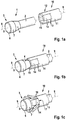
- An inventive tool consists according to a first embodiment, which in Fig. 1a is shown, consisting of a core 1 and a cutting sleeve 10, wherein the core 1 consists of a cylindrical shaft 2 and a stamping on the distal end of the punch 3.
- the punch 3 is also substantially cylindrical and has a larger outer diameter than the shaft 2.
- the punch In its proximal end portion, the punch a substantially conical abutment surface 4, the diameter of which widens distally on the outer diameter of the punch 3 from the diameter of the shaft 2.
- the edge passes with a chamfer 6 in the lateral surface 7 of the punch 3.
- the cutting sleeve 10 comprises a cylindrical shaft 11 whose distal end portion 12 is divided into a plurality of segments 14 by a plurality of longitudinally extending slots 13. The segments have a chamfer or a rounding 15 on their distal inner side.
- the inner diameter of the shaft 11 of the cutting sleeve 10 is matched to the outer diameter of the shaft 2 of the core 1, that the cutting sleeve on the shaft 2 of the core 1 is longitudinally displaceable, in particular from the proximal direction can be pushed over the shaft 2.
- the outer diameter of the cutting sleeve 10 coincides with that of the punch 3.
- the wall thickness of the cutting sleeve 10 in Fig. 1a and the other figures in relation to the diameter shown larger than is preferred in the described embodiments.
- a handle or a coupling for connection to a drive may be provided (not shown).
- Fig. 1b shows the cutting sleeve 10 in a position in which it is pushed so far distally over the shaft 2 of the core that the segments 14 touch the contact surface 4 or almost touch, but not spread.
- the cutting sleeve 10 and the core 1 are arranged coaxially with a common longitudinal axis 9 after pushing. If now the cutting sleeve 10 is further advanced in the distal direction, the segments 14 are spread by pushing onto the contact surface 4 and thereby project beyond the outer contour of the arrangement of the core 1 and the cutting sleeve 10 (FIG. Fig. 1c ).
- a transition region 17 between the segments 14 and the shaft 11 of the cutting sleeve acts as a hinge and is elastically bendable formed for this purpose.
- the pushing and spreading is facilitated by the rounding 15 at the distal inner edge of the segments 14.
- Each segment 14 has a cutting edge 16 at a lateral outer edge.
- the shaft 2 and the punch 3 each having an inner cavity, wherein the cavity of the shaft 2 is connected to that of the punch 3 and to the proximal end of the shaft 2 for connection to an exhaust continuous (not shown).
- the lateral surface 7 of the punch 3 has a number of penetrating into the run-up surface 4 openings 8, through which the cavity of the punch 3 is in communication with the outside space.
- the inner diameter of the cutting sleeve of the shaft 11 of the cutting sleeve 10 is greater than the outer diameter of the shaft 2 of the core 1, so that rinsing liquid can be guided into the region of the contact surface 4 by the intermediate space formed thereby.
- a flushing connection can be provided for this purpose (not shown). In this way, a closed rinse cycle for the removal of bone tissue, which has been removed with the cutting edges 16, be created.
- proximal end portion of the shaft 2 of the core 1 and the cutting sleeve 10 rinsing and suction ports and a handle or a clutch for connection to a drive are arranged.
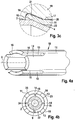
- Fig. 3a and 3b is the tool according to Fig. 2 in two relative positions, which correspond to those for the first embodiment
- Fig. 1b and 1c correspond to shown situations, each shown in a sectional longitudinal section
- Fig. 3c shows an enlarged detail.
- the segments 14 are within the outer contour defined by the outside of the shaft 11 of the cutting sleeve 10 and by the lateral surface 7 of the punch 3. By sliding on the contact surface 4, the segments 14 are spread and then protrude beyond the outer contour ( Fig. 3b ).
- the distal inner edge of the segments 14 is provided with a rounding 15 in order to reduce friction and wear when sliding on the stop surface 4.
- an edge formed by the execution of the slot 13 is formed as a cutting edge 16.
- the cutting edge 16 is rounded in a longitudinal profile and extends in the proximal direction to the transition region 17 between the respective segment 14 and the shaft 11 of the cutting sleeve 10 or close to this to facilitate the working out of the undercut 21. In order to be able to remove tissue even during a displacement in the distal direction, the cutting edge 16 extends as far as into or into the rounding 15.
- FIGS. 3a to 3c Shown are the core 1, a distal portion of the shaft 2 of the core 1, the segments 14 and a distal portion of the shaft 11 of the cutting sleeve 10 in an inserted into a bone 19 bore 20 which is formed as a blind hole with a conical bottom 33 , introduced.
- the outer diameter of the punch 3 and the cutting sleeve 10 is slightly smaller than the inner diameter of the bore 20 to facilitate insertion into the bore 20. Furthermore, this makes flushing easier.
- rinsing liquid is supplied through a continuous gap 22 extending between the shaft 2 of the core 1 and the shaft 11 of the cutting sleeve 10, passes through the working region of the cutting edges 16, passes through the openings 8 in the interior of the ram 3 and the shaft 2 of the Kerns arranged cavity 18 and is discharged through this proximally.
- proximal end portion of the shaft 2 of the core 1 and the cutting sleeve 10 rinsing and suction ports and a clutch for connection to a drive are arranged.
- the core 1 and the cutting sleeve 10 are inserted together or successively into the bore 20 until the punch 3 abuts with its end wall 5 at the bottom of the blind hole ( Fig. 3a ). Then, the cutting sleeve 10 is set in rotation about the longitudinal axis 9 and further displaced relative to the core 1 in the distal direction to spread the segments 14 and to introduce an undercut 21 in the side wall of the bore 20 ( Fig. 3b and 3c ).
- a third embodiment of the invention is shown in two different views, wherein in Fig. 4b which is slid onto the shaft 2 of the core 1 cutting sleeve 10 is cut in the region of the segments 14 transverse to the longitudinal axis.
- the slits 13 introduced distally into the cutting sleeve 10 are made wide in order to to create enough space for the flow through with rinsing liquid.
- the cutting edge 16 formed as a tangentially projecting edge on a side wall of the slot 13. This allows a particularly effective removal of bone material.
- a direction of rotation when operating the tool is predetermined, wherein the cutting edge 16 is arranged on the leading edge of the segment 14.
- the following edge 23 has no cutting edge.
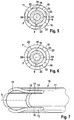
- the shaft 2 of the core 1 carries on its outer side a plurality of longitudinally extending ribs 24 which divide the gap 22 in longitudinally extending cavities, can be guided by the rinsing liquid in the region of the cutting edges 16 and also a secure guidance of the shaft 11 of the cutting sleeve 10 on the shaft 2 of the core 1 ensure.
- the cutting sleeve 10 and the core 1 are formed as described above.
- the outer sides of the segments 14 may be inclined, so that the leading edge, which is formed as a cutting edge 16, is increased relative to the following edge 23. As a result, the cutting action and the removal of the generated bone chips are further improved. Otherwise, the fourth embodiment corresponds to the in Fig. 4a and 4b illustrated third embodiment.
- Fig. 6 is in one of the Fig. 4b corresponding representation indicated that the ribs 24 may be disposed on the inside of the shaft 11 of the cutting sleeve 10.
- this explains the gap 22 is divided into axially extending cavities for the passage of flushing fluid; Furthermore, the ribs 24 serve for the secure guidance of the cutting sleeve 10 on the shaft 2.
- the segments 14 may be rounded off distally according to a further embodiment of the invention.
- the cutting edges 16, which extend here along the outside of the segments 14, are therefore curved and extend at least up to the vertex of the respective segment 14.
- a cutting sleeve 10 designed in this way allows a particularly sensitive removal of bone tissue.
- a cutting sleeve 10 according to the embodiments described above can also be designed such that in the transition region 17 between the segments 14 and the shaft 11 of the cutting sleeve 10, the wall thickness of the cutting sleeve 10 is reduced to allow for easier bending of the segment 14.
- a groove or notch 25 in the transition region 17 may be introduced, as exemplified in the FIGS. 8a and 8b in two different axial relative positions of core 1 and cutting sleeve 10, the in Fig. 3a and 3b shown, is shown. Incidentally, the correspond in the FIGS. 6 to 8b illustrated embodiments of the invention described above.
- Fig. 9 the punch 3 of a core 1 according to an eighth embodiment of the invention is shown.
- the punch 3 is likewise arranged at the distal end of a shaft 2 and merges with a conical contact surface 4 into the lateral surface of the shaft 2.
- the cylindrical portion of the punch 3 has no apertures, however, the stop surface 4 has apertures 26 which may be elongated and which form a connection from the outside into the internal cavity of the punch 3 which is connected to the continuous cavity of the stem 2 , In order to reduce friction by the rotation of the voltage applied to the contact surface 4 segments, the apertures 26 may have rounded edges.
- FIG Fig. 10 Another embodiment of a punch 3 is shown in FIG Fig. 10 shown.
- the contact surface 4 is bell-shaped, wherein the slope of the run-up slope formed thereby increases from proximal to distal.
- the stamp 3 in the in the FIGS. 9 and 10 shown embodiments as described above and can be used in combination with the cutting sleeves 10 described above.
- the contact surface 4 may have one or more openings 26 to improve the flushing in particular at the beginning of the elaboration of the undercut.
- a step 28 may be provided in a distal end region of the shaft 2, said step being provided with a step 29 on the inside of the shaft 11 of the cutting sleeve 10 cooperates to limit the displacement in the axial direction.
- an outer diameter of a cavity to be produced can be determined particularly accurately. Incidentally, this is in Fig. 11 shown embodiment as the embodiments described above.
- a punch 3 and a shaft 2 and a core 1 formed by the punch 3 and the shaft 2 with a cutting sleeve 10 which are also encompassed by the invention.
- the punch 3 according to the embodiments described above may in particular have an outer diameter of about 2 to 5 mm.
- the outer diameter of the cutting sleeve 10 is also about 2 to 5 mm, wherein the cutting sleeve 10 and the segments 14 may have a wall thickness of for example about 0.2 mm.
- the cutting sleeve 10 is made of a suitable for surgical application elastic material, preferably made of an elastic metallic material, such as spring steel or Nitinol.
- the punch 3 and the shaft 2 of the core 1 consist of a suitable for the surgical application of metallic or non-metallic material, such as stainless steel or polyetheretherketone (PEEK).
- the core 1 may be formed in one piece.
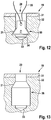
- Fig. 12 schematically an example of a cavity 30 is shown, which can be created with a tool according to the invention.
- a cylindrical bore 20 is first introduced with a conventional surgical bone drill.
- the bore 20 penetrates the outer layer (cortex 31) and terminates in the cancellous bone 32 of the bone 19.
- the bottom 33 of the bore 20 is, depending on the shape of the drill used, usually conical. After the introduction of the bore 20, the drill is pulled out of this again.
- the punch 3 of the core 1 is inserted into the bore 20 until it rests against the bottom 33 of the bore.
- the pushed onto the shaft 2 of the core 1 cutting sleeve 10 is inserted into the bore 20 (s. Fig. 1b . 3a . 8a ).
- the cutting sleeve 10 is pushed by touching the run-on surface 4 while rotating about its longitudinal axis even further in the distal direction, whereby the segments 14 are spread open and cut into the surrounding bone tissue (cancellous bone 32) (s. Fig. 1c . 3b . 3c . 8b ).
- the core 1 and the cutting sleeve 10 in the in Fig. 1b .
- the cutting sleeve are moved further in the distal direction.
- the core 1 is not rotated, but this may also be possible.
- the cutting sleeve 10 When an undercut 21 of sufficient depth has been created, first the cutting sleeve 10 is retracted in the proximal direction. The segments 14 are after sliding down from the contact surface 4 again within the extension of the outer contour of the shaft 11 of the cutting sleeve 10 (s. Fig. 1b . 3a . 8a ), so that the cutting sleeve 10 can be removed without further removal of bone tissue from the bore 20. Thereafter, the core 1 is pulled out of the bore 20. In the cavity 30, which is formed by the undercut 21, then a bone anchor 34 is inserted, spread with a spreading mechanism and thereby anchored in the cavity 30. The bone anchor 34 thus makes it possible, for example via a thread 35, to hold soft tissue or even a surgical implant on the outside of the bone 19.
- substantially cylindrical cavity 36 are created in the bone 19.
- 10 of the core 1 and the cutting sleeve 10 are moved together in the proximal direction with further rotation of the cutting sleeve.
- a cavity 36 of sufficient length has been created, the core 1 is retained or slightly moved in the distal direction and the
- a cavity 30, 36 are provided for the positive fixing of a bone anchor with suitable dimensions for many applications.
- an undercut of approx. 0.5 mm depth is sufficient, ie the cavity 30, 36 is widened by approx. 1 mm in diameter compared with the bore.
- the bone anchor may, for example, have a length of about 10 mm.
Landscapes
- Health & Medical Sciences (AREA)
- Surgery (AREA)
- Life Sciences & Earth Sciences (AREA)
- Biomedical Technology (AREA)
- Medical Informatics (AREA)
- Orthopedic Medicine & Surgery (AREA)
- Oral & Maxillofacial Surgery (AREA)
- Engineering & Computer Science (AREA)
- Dentistry (AREA)
- Heart & Thoracic Surgery (AREA)
- Nuclear Medicine, Radiotherapy & Molecular Imaging (AREA)
- Molecular Biology (AREA)
- Animal Behavior & Ethology (AREA)
- General Health & Medical Sciences (AREA)
- Public Health (AREA)
- Veterinary Medicine (AREA)
- Surgical Instruments (AREA)
Claims (11)
- Outil de fabrication d'une contre-dépouille (21) dans un os (19), comprenant un noyau (1) avec une tige (2) et un poinçon (3) attaché à une extrémité distale de la tige (2), le poinçon (3) présentant, dans une région de transition à la tige (2), un biseau de montée montant dans la direction distale, et une douille de coupe (10) disposée de manière déplaçable longitudinalement sur la tige (2), dont l'extrémité distale est formée par au moins un segment (14) pouvant être écarté en le poussant sur le biseau de montée, l'au moins un segment (14) présentant au moins une arête de coupe disposée latéralement (16) et la douille de coupe (10), au moins dans une région de transition entre l'au moins un segment (14) et une tige (11) de la douille de coupe (10), se composant d'un matériau élastique.
- Outil selon la revendication 1, caractérisé en ce que l'extrémité distale de la douille de coupe (10) est formée par une pluralité de segments (14) présentant à chaque fois au moins une arête de coupe (16) disposée latéralement, lesquels segments sont séparés les uns des autres par des fentes (13) pratiquées du côté distal dans l'extrémité distale de la douille de coupe (10).
- Outil selon la revendication 1 ou 2, caractérisé en ce que l'arête de coupe ou les arêtes de coupe (16) est/sont disposée (s) obliquement par rapport à un axe longitudinal (9) de la douille de coupe (10) .
- Outil selon l'une quelconque des revendications précédentes, caractérisé en ce que l'arête de coupe ou les arêtes de coupe (16) est/sont courbée(s) et/ou dentée(s).
- Outil selon l'une quelconque des revendications précédentes, caractérisé en ce que l'au moins un segment (14) présente, par rapport à une direction de rotation prédéfinie de la douille de coupe (10), une arête d'attaque et une arête de fuite (23), l'arête d'attaque étant réalisée au moins en partie sous forme d'arête de coupe (16) et l'arête de fuite (23) étant disposée radialement plus profondément que l'arête d'attaque.
- Outil selon l'une quelconque des revendications précédentes, caractérisé en en ce qu'une région de transition entre l'au moins un segment (14) et une tige (11) de la douille de coupe (10) est affaiblie.
- Outil selon l'une quelconque des revendications précédentes, caractérisé en ce qu'une arête distale intérieure de l'au moins un segment (14) présente un arrondi (15) ou un chanfrein.
- Outil selon l'une quelconque des revendications précédentes, caractérisé en ce que le biseau de montée est réalisé sous forme de surface de montée (4) essentiellement conique ou en forme de cloche.
- Outil selon l'une quelconque des revendications précédentes, caractérisé en ce que la tige (2) du noyau (1) ou une région de transition entre le poinçon (3) et la tige (2) du noyau (1) dans la direction axiale présente une butée qui coopère avec une butée de la douille de coupe (10) pour limiter une course de déplacement axiale de la douille de coupe (10) par rapport au noyau (1).
- Outil selon l'une quelconque des revendications précédentes, caractérisé en ce qu'entre la tige (2) du noyau (1) et la douille de coupe (10) est disposé un espace intermédiaire (22) s'étendant axialement.
- Outil selon l'une quelconque des revendications précédentes, caractérisé en ce que le poinçon (3) et la tige (2) du noyau (1) présentent une cavité interne (18) s'étendant en continu jusque dans une région d'extrémité proximale de la tige (2) et le poinçon (3) présente au moins un orifice latéral (8) .
Priority Applications (1)
| Application Number | Priority Date | Filing Date | Title |
|---|---|---|---|
| US14/661,942 US9848891B2 (en) | 2014-03-18 | 2015-03-18 | Tool and method for generating an undercut in a bone |
Applications Claiming Priority (1)
| Application Number | Priority Date | Filing Date | Title |
|---|---|---|---|
| DE102014003721.5A DE102014003721A1 (de) | 2014-03-18 | 2014-03-18 | Werkzeug und Verfahren zum Erzeugen eines Hinterschnitts in einem Knochen |
Publications (2)
| Publication Number | Publication Date |
|---|---|
| EP2921118A1 EP2921118A1 (fr) | 2015-09-23 |
| EP2921118B1 true EP2921118B1 (fr) | 2017-12-20 |
Family
ID=52626949
Family Applications (1)
| Application Number | Title | Priority Date | Filing Date |
|---|---|---|---|
| EP15000497.6A Active EP2921118B1 (fr) | 2014-03-18 | 2015-02-20 | Outil de fabrication d'une contre-dépouille dans un os |
Country Status (3)
| Country | Link |
|---|---|
| US (1) | US9848891B2 (fr) |
| EP (1) | EP2921118B1 (fr) |
| DE (1) | DE102014003721A1 (fr) |
Families Citing this family (9)
| Publication number | Priority date | Publication date | Assignee | Title |
|---|---|---|---|---|
| US10076349B2 (en) | 2013-03-15 | 2018-09-18 | Misonix, Inc. | Ultrasonic surgical drill and associated surgical method |
| US11219466B2 (en) * | 2018-06-06 | 2022-01-11 | Acumed Llc | Orthopedic reamer with expandable cutting head |
| EP4233741B1 (fr) | 2014-10-19 | 2025-10-08 | T.A.G. Medical Products Corporation Ltd. | Kit comprenant un système de guidage et un dispositif d'ablation de matière osseuse |
| EP3282956A4 (fr) * | 2015-04-09 | 2019-01-16 | T.A.G. Medical Devices - Agriculture Cooperative Ltd. | Dispositif de retrait de matière osseuse et son procédé d'utilisation |
| WO2017137998A2 (fr) | 2016-02-11 | 2017-08-17 | T.A.G. Medical Devices - Agriculture Cooperative Ltd. | Dispositif de retrait de matière osseuse et procédé pour l'utiliser |
| WO2017187436A1 (fr) | 2016-04-24 | 2017-11-02 | T.A.G. Medical Devices - Agriculture Cooperative Ltd. | Dispositif de guidage et procédés d'utilisation correspondants |
| AU2019298584B2 (en) * | 2018-07-03 | 2025-03-13 | Bosonic Ag | Device for perforating a dense bone layer |
| CN112672670B (zh) | 2018-08-01 | 2024-08-30 | Tag医疗器材农业合作有限公司 | 可调整钻孔装置及其使用方法 |
| DE102020111483A1 (de) | 2020-04-28 | 2021-10-28 | H & B Electronic Gmbh & Co. Kg | Hinterschnittwerkzeug |
Family Cites Families (22)
| Publication number | Priority date | Publication date | Assignee | Title |
|---|---|---|---|---|
| DE3126472A1 (de) * | 1981-07-04 | 1983-01-20 | Hawera Probst Gmbh + Co, 7980 Ravensburg | Bohrwerkzeug zur radialen erweiterung einer zylindrischen grundbohrung |
| US4635737A (en) * | 1984-03-08 | 1987-01-13 | Kabushiki Kaishi Miyanaga | Undercutting drill |
| JP2598515B2 (ja) * | 1989-04-24 | 1997-04-09 | 株式会社ミヤナガ | 拡径部付孔穿孔装置 |
| US5004421A (en) * | 1990-07-27 | 1991-04-02 | Sargon Lazarof | Dental implant and method of using same |
| US5810523A (en) * | 1995-02-28 | 1998-09-22 | Kabushiki Kaisha Miyanaga | Apparatus for drilling a hole having an undercut space |
| JP2862807B2 (ja) * | 1995-02-28 | 1999-03-03 | 株式会社ミヤナガ | アンダーカット部付き孔の穿孔装置 |
| US5816759A (en) * | 1997-05-08 | 1998-10-06 | Illinois Tool Works Inc. | Expansion anchor and method therefor |
| US5928239A (en) | 1998-03-16 | 1999-07-27 | University Of Washington | Percutaneous surgical cavitation device and method |
| US6851492B2 (en) * | 1999-07-21 | 2005-02-08 | Kabushiki Kaisha Zen Kenchiku Sekkei Jimusho | Fastener, hammering jig for installing the fastener, and drill bit for working undercut hole |
| US20070123889A1 (en) | 2005-10-14 | 2007-05-31 | Malandain Hugues F | Mechanical cavity-creation surgical device and methods and kits for using such devices |
| DE102006007232A1 (de) * | 2006-02-15 | 2007-08-16 | Hager & Meisinger Gmbh | Hinterschnittwerkzeug und Plateau-Bohrer |
| US8221479B2 (en) * | 2007-01-19 | 2012-07-17 | Pbj, Llc | Orthopedic screw insert |
| AU2008218267A1 (en) * | 2007-02-22 | 2008-08-28 | Spine View, Inc. | Expandable rotating device and method for tissue aspiration |
| US8157804B2 (en) * | 2007-03-07 | 2012-04-17 | Vertech, Inc. | Expandable blade device for stabilizing long bone fractures |
| EP2098177B1 (fr) | 2008-03-03 | 2013-10-16 | Arthrex, Inc. | Découpeur et fraise combinés |
| US8906060B2 (en) | 2009-06-24 | 2014-12-09 | Karl Storz Gmbh & Co. Kg | Method and apparatus for soft tissue fixation to bone |
| US20130138110A1 (en) * | 2010-08-06 | 2013-05-30 | Adam Hacking | Devices for adapting bone |
| DE102010046419B4 (de) * | 2010-09-23 | 2013-03-07 | Richard Wolf Gmbh | Medizinischer Bohrer |
| GB2498209B (en) * | 2012-01-06 | 2018-12-12 | Imperius Ltd | Fasteners |
| MX2015007111A (es) * | 2012-12-05 | 2015-10-12 | Smith & Nephew Inc | Instrumento quirurgico. |
| BR112015020189A2 (pt) * | 2013-03-12 | 2017-07-18 | Smith & Nephew Inc | alargador de fio-guia retrógrado |
| US20150313611A1 (en) * | 2014-05-02 | 2015-11-05 | Howmedica Osteonics Corp. | Undercutting bone drills and methods of use |
-
2014
- 2014-03-18 DE DE102014003721.5A patent/DE102014003721A1/de not_active Withdrawn
-
2015
- 2015-02-20 EP EP15000497.6A patent/EP2921118B1/fr active Active
- 2015-03-18 US US14/661,942 patent/US9848891B2/en active Active
Non-Patent Citations (1)
| Title |
|---|
| None * |
Also Published As
| Publication number | Publication date |
|---|---|
| US20150265287A1 (en) | 2015-09-24 |
| DE102014003721A1 (de) | 2015-09-24 |
| US9848891B2 (en) | 2017-12-26 |
| EP2921118A1 (fr) | 2015-09-23 |
Similar Documents
| Publication | Publication Date | Title |
|---|---|---|
| EP2921118B1 (fr) | Outil de fabrication d'une contre-dépouille dans un os | |
| DE102008003403B4 (de) | Anordnung mit einem Instrument zur Vorbereitung oder Durchführung der Insertion eines Implantats | |
| DE69925959T2 (de) | Ultraschalltrokar | |
| EP2096982B1 (fr) | Dispositif et procédé pour intervention minimale invasive sur la colonne vertébrale | |
| EP2432402B1 (fr) | Dispositif permettant l'introduction d'un clou courbe dans un os | |
| EP0432260B1 (fr) | Dispositif de guidage d'un osteotome pour osteotomie d'os longs | |
| EP0682917B1 (fr) | Outil de vissage pour une vis, consitant en un boulon et en un écrou qui peut être vissé sur ledit boulon | |
| EP2497432B1 (fr) | Outil d'insertion médical | |
| WO2011076364A1 (fr) | Instrument chirurgical pour le raccordement amovible d'une pièce à main à un outil chirurgical | |
| DE19908721A1 (de) | Instrument zum Schneiden von biologischem und insbesondere menschlichem Gewebe | |
| DE102004009608A1 (de) | Endoskopisches Behandlungsinstrument | |
| EP0118778A1 (fr) | Clou d'ancrage | |
| WO2006087159A1 (fr) | Systeme de fixation orthopedique | |
| EP3261566B1 (fr) | Plaque d'ostéosynthèse et kit chirurgical pour la fixation de fragments osseux | |
| DE19705571A1 (de) | Kieferschraubenimplantat | |
| DE3321091A1 (de) | Verfahren und vorrichtung zum einbringen oder erweitern von loechern in kunststoffbehaeltern | |
| DE202007007322U1 (de) | Instrumentensatz zur minimal invasiven Vorbereitung einer Knochennagelung | |
| DE102005014624B4 (de) | Arthroskopisches Instrumentarium | |
| WO2017206984A1 (fr) | Instrument médical servant à enlever des fragments dentaires | |
| EP2702950A1 (fr) | Système d'outil médical, ainsi que poignée et outil pour un système d'outil médical | |
| DE102021001608B4 (de) | Chirurgisches Bohr-Instrument | |
| EP2862654B1 (fr) | Système perforateur | |
| EP4041093B1 (fr) | Instrument chirurgical, procédé de production d'un instrument chirurgical et utilisation d'une articulation rotoïde pour former un outil de coupe d'un instrument chirurgical | |
| DE3644490A1 (de) | Knochenbiopsiebesteck | |
| DE102009057434A1 (de) | Vorrichtung und Verfahren zur Knochenzemententfernung |
Legal Events
| Date | Code | Title | Description |
|---|---|---|---|
| PUAI | Public reference made under article 153(3) epc to a published international application that has entered the european phase |
Free format text: ORIGINAL CODE: 0009012 |
|
| AK | Designated contracting states |
Kind code of ref document: A1 Designated state(s): AL AT BE BG CH CY CZ DE DK EE ES FI FR GB GR HR HU IE IS IT LI LT LU LV MC MK MT NL NO PL PT RO RS SE SI SK SM TR |
|
| AX | Request for extension of the european patent |
Extension state: BA ME |
|
| 17P | Request for examination filed |
Effective date: 20151208 |
|
| RBV | Designated contracting states (corrected) |
Designated state(s): AL AT BE BG CH CY CZ DE DK EE ES FI FR GB GR HR HU IE IS IT LI LT LU LV MC MK MT NL NO PL PT RO RS SE SI SK SM TR |
|
| 17Q | First examination report despatched |
Effective date: 20170221 |
|
| GRAP | Despatch of communication of intention to grant a patent |
Free format text: ORIGINAL CODE: EPIDOSNIGR1 |
|
| GRAJ | Information related to disapproval of communication of intention to grant by the applicant or resumption of examination proceedings by the epo deleted |
Free format text: ORIGINAL CODE: EPIDOSDIGR1 |
|
| INTG | Intention to grant announced |
Effective date: 20170705 |
|
| INTC | Intention to grant announced (deleted) | ||
| GRAP | Despatch of communication of intention to grant a patent |
Free format text: ORIGINAL CODE: EPIDOSNIGR1 |
|
| INTG | Intention to grant announced |
Effective date: 20170908 |
|
| GRAS | Grant fee paid |
Free format text: ORIGINAL CODE: EPIDOSNIGR3 |
|
| GRAA | (expected) grant |
Free format text: ORIGINAL CODE: 0009210 |
|
| AK | Designated contracting states |
Kind code of ref document: B1 Designated state(s): AL AT BE BG CH CY CZ DE DK EE ES FI FR GB GR HR HU IE IS IT LI LT LU LV MC MK MT NL NO PL PT RO RS SE SI SK SM TR |
|
| REG | Reference to a national code |
Ref country code: GB Ref legal event code: FG4D Free format text: NOT ENGLISH |
|
| REG | Reference to a national code |
Ref country code: CH Ref legal event code: EP |
|
| RAP2 | Party data changed (patent owner data changed or rights of a patent transferred) |
Owner name: KARL STORZ SE & CO. KG |
|
| REG | Reference to a national code |
Ref country code: IE Ref legal event code: FG4D Free format text: LANGUAGE OF EP DOCUMENT: GERMAN |
|
| REG | Reference to a national code |
Ref country code: AT Ref legal event code: REF Ref document number: 955637 Country of ref document: AT Kind code of ref document: T Effective date: 20180115 |
|
| REG | Reference to a national code |
Ref country code: DE Ref legal event code: R096 Ref document number: 502015002592 Country of ref document: DE |
|
| REG | Reference to a national code |
Ref country code: FR Ref legal event code: PLFP Year of fee payment: 4 |
|
| REG | Reference to a national code |
Ref country code: DE Ref legal event code: R081 Ref document number: 502015002592 Country of ref document: DE Owner name: KARL STORZ SE & CO. KG INTELLECTUAL PROPERTY, DE Free format text: FORMER OWNER: KARL STORZ GMBH & CO. KG, 78532 TUTTLINGEN, DE Ref country code: DE Ref legal event code: R081 Ref document number: 502015002592 Country of ref document: DE Owner name: KARL STORZ SE & CO. KG, DE Free format text: FORMER OWNER: KARL STORZ GMBH & CO. KG, 78532 TUTTLINGEN, DE |
|
| REG | Reference to a national code |
Ref country code: NL Ref legal event code: MP Effective date: 20171220 |
|
| PG25 | Lapsed in a contracting state [announced via postgrant information from national office to epo] |
Ref country code: SE Free format text: LAPSE BECAUSE OF FAILURE TO SUBMIT A TRANSLATION OF THE DESCRIPTION OR TO PAY THE FEE WITHIN THE PRESCRIBED TIME-LIMIT Effective date: 20171220 Ref country code: LT Free format text: LAPSE BECAUSE OF FAILURE TO SUBMIT A TRANSLATION OF THE DESCRIPTION OR TO PAY THE FEE WITHIN THE PRESCRIBED TIME-LIMIT Effective date: 20171220 Ref country code: NO Free format text: LAPSE BECAUSE OF FAILURE TO SUBMIT A TRANSLATION OF THE DESCRIPTION OR TO PAY THE FEE WITHIN THE PRESCRIBED TIME-LIMIT Effective date: 20180320 Ref country code: FI Free format text: LAPSE BECAUSE OF FAILURE TO SUBMIT A TRANSLATION OF THE DESCRIPTION OR TO PAY THE FEE WITHIN THE PRESCRIBED TIME-LIMIT Effective date: 20171220 |
|
| REG | Reference to a national code |
Ref country code: LT Ref legal event code: MG4D |
|
| PG25 | Lapsed in a contracting state [announced via postgrant information from national office to epo] |
Ref country code: BG Free format text: LAPSE BECAUSE OF FAILURE TO SUBMIT A TRANSLATION OF THE DESCRIPTION OR TO PAY THE FEE WITHIN THE PRESCRIBED TIME-LIMIT Effective date: 20180320 Ref country code: HR Free format text: LAPSE BECAUSE OF FAILURE TO SUBMIT A TRANSLATION OF THE DESCRIPTION OR TO PAY THE FEE WITHIN THE PRESCRIBED TIME-LIMIT Effective date: 20171220 Ref country code: RS Free format text: LAPSE BECAUSE OF FAILURE TO SUBMIT A TRANSLATION OF THE DESCRIPTION OR TO PAY THE FEE WITHIN THE PRESCRIBED TIME-LIMIT Effective date: 20171220 Ref country code: GR Free format text: LAPSE BECAUSE OF FAILURE TO SUBMIT A TRANSLATION OF THE DESCRIPTION OR TO PAY THE FEE WITHIN THE PRESCRIBED TIME-LIMIT Effective date: 20180321 Ref country code: LV Free format text: LAPSE BECAUSE OF FAILURE TO SUBMIT A TRANSLATION OF THE DESCRIPTION OR TO PAY THE FEE WITHIN THE PRESCRIBED TIME-LIMIT Effective date: 20171220 |
|
| PG25 | Lapsed in a contracting state [announced via postgrant information from national office to epo] |
Ref country code: NL Free format text: LAPSE BECAUSE OF FAILURE TO SUBMIT A TRANSLATION OF THE DESCRIPTION OR TO PAY THE FEE WITHIN THE PRESCRIBED TIME-LIMIT Effective date: 20171220 |
|
| PG25 | Lapsed in a contracting state [announced via postgrant information from national office to epo] |
Ref country code: CZ Free format text: LAPSE BECAUSE OF FAILURE TO SUBMIT A TRANSLATION OF THE DESCRIPTION OR TO PAY THE FEE WITHIN THE PRESCRIBED TIME-LIMIT Effective date: 20171220 Ref country code: SK Free format text: LAPSE BECAUSE OF FAILURE TO SUBMIT A TRANSLATION OF THE DESCRIPTION OR TO PAY THE FEE WITHIN THE PRESCRIBED TIME-LIMIT Effective date: 20171220 Ref country code: ES Free format text: LAPSE BECAUSE OF FAILURE TO SUBMIT A TRANSLATION OF THE DESCRIPTION OR TO PAY THE FEE WITHIN THE PRESCRIBED TIME-LIMIT Effective date: 20171220 Ref country code: EE Free format text: LAPSE BECAUSE OF FAILURE TO SUBMIT A TRANSLATION OF THE DESCRIPTION OR TO PAY THE FEE WITHIN THE PRESCRIBED TIME-LIMIT Effective date: 20171220 Ref country code: CY Free format text: LAPSE BECAUSE OF FAILURE TO SUBMIT A TRANSLATION OF THE DESCRIPTION OR TO PAY THE FEE WITHIN THE PRESCRIBED TIME-LIMIT Effective date: 20171220 |
|
| PG25 | Lapsed in a contracting state [announced via postgrant information from national office to epo] |
Ref country code: RO Free format text: LAPSE BECAUSE OF FAILURE TO SUBMIT A TRANSLATION OF THE DESCRIPTION OR TO PAY THE FEE WITHIN THE PRESCRIBED TIME-LIMIT Effective date: 20171220 Ref country code: IS Free format text: LAPSE BECAUSE OF FAILURE TO SUBMIT A TRANSLATION OF THE DESCRIPTION OR TO PAY THE FEE WITHIN THE PRESCRIBED TIME-LIMIT Effective date: 20180420 Ref country code: PL Free format text: LAPSE BECAUSE OF FAILURE TO SUBMIT A TRANSLATION OF THE DESCRIPTION OR TO PAY THE FEE WITHIN THE PRESCRIBED TIME-LIMIT Effective date: 20171220 Ref country code: SM Free format text: LAPSE BECAUSE OF FAILURE TO SUBMIT A TRANSLATION OF THE DESCRIPTION OR TO PAY THE FEE WITHIN THE PRESCRIBED TIME-LIMIT Effective date: 20171220 |
|
| REG | Reference to a national code |
Ref country code: CH Ref legal event code: PL |
|
| REG | Reference to a national code |
Ref country code: DE Ref legal event code: R097 Ref document number: 502015002592 Country of ref document: DE |
|
| PG25 | Lapsed in a contracting state [announced via postgrant information from national office to epo] |
Ref country code: MT Free format text: LAPSE BECAUSE OF FAILURE TO SUBMIT A TRANSLATION OF THE DESCRIPTION OR TO PAY THE FEE WITHIN THE PRESCRIBED TIME-LIMIT Effective date: 20171220 Ref country code: MC Free format text: LAPSE BECAUSE OF FAILURE TO SUBMIT A TRANSLATION OF THE DESCRIPTION OR TO PAY THE FEE WITHIN THE PRESCRIBED TIME-LIMIT Effective date: 20171220 |
|
| PLBE | No opposition filed within time limit |
Free format text: ORIGINAL CODE: 0009261 |
|
| STAA | Information on the status of an ep patent application or granted ep patent |
Free format text: STATUS: NO OPPOSITION FILED WITHIN TIME LIMIT |
|
| REG | Reference to a national code |
Ref country code: IE Ref legal event code: MM4A |
|
| REG | Reference to a national code |
Ref country code: BE Ref legal event code: MM Effective date: 20180228 |
|
| PG25 | Lapsed in a contracting state [announced via postgrant information from national office to epo] |
Ref country code: DK Free format text: LAPSE BECAUSE OF FAILURE TO SUBMIT A TRANSLATION OF THE DESCRIPTION OR TO PAY THE FEE WITHIN THE PRESCRIBED TIME-LIMIT Effective date: 20171220 Ref country code: LI Free format text: LAPSE BECAUSE OF NON-PAYMENT OF DUE FEES Effective date: 20180228 Ref country code: LU Free format text: LAPSE BECAUSE OF NON-PAYMENT OF DUE FEES Effective date: 20180220 Ref country code: CH Free format text: LAPSE BECAUSE OF NON-PAYMENT OF DUE FEES Effective date: 20180228 |
|
| 26N | No opposition filed |
Effective date: 20180921 |
|
| PG25 | Lapsed in a contracting state [announced via postgrant information from national office to epo] |
Ref country code: IE Free format text: LAPSE BECAUSE OF NON-PAYMENT OF DUE FEES Effective date: 20180220 |
|
| PG25 | Lapsed in a contracting state [announced via postgrant information from national office to epo] |
Ref country code: SI Free format text: LAPSE BECAUSE OF FAILURE TO SUBMIT A TRANSLATION OF THE DESCRIPTION OR TO PAY THE FEE WITHIN THE PRESCRIBED TIME-LIMIT Effective date: 20171220 Ref country code: BE Free format text: LAPSE BECAUSE OF NON-PAYMENT OF DUE FEES Effective date: 20180228 |
|
| REG | Reference to a national code |
Ref country code: DE Ref legal event code: R082 Ref document number: 502015002592 Country of ref document: DE Representative=s name: JESCHKE, ALEXANDER, DIPL.-ING. (FH) DR.RER.NAT, DE Ref country code: DE Ref legal event code: R082 Ref document number: 502015002592 Country of ref document: DE Representative=s name: WEIDNER STERN JESCHKE PATENTANWAELTE PARTNERSC, DE |
|
| PG25 | Lapsed in a contracting state [announced via postgrant information from national office to epo] |
Ref country code: TR Free format text: LAPSE BECAUSE OF FAILURE TO SUBMIT A TRANSLATION OF THE DESCRIPTION OR TO PAY THE FEE WITHIN THE PRESCRIBED TIME-LIMIT Effective date: 20171220 |
|
| REG | Reference to a national code |
Ref country code: DE Ref legal event code: R082 Ref document number: 502015002592 Country of ref document: DE Representative=s name: WEIDNER STERN JESCHKE PATENTANWAELTE PARTNERSC, DE |
|
| PG25 | Lapsed in a contracting state [announced via postgrant information from national office to epo] |
Ref country code: PT Free format text: LAPSE BECAUSE OF FAILURE TO SUBMIT A TRANSLATION OF THE DESCRIPTION OR TO PAY THE FEE WITHIN THE PRESCRIBED TIME-LIMIT Effective date: 20171220 |
|
| PG25 | Lapsed in a contracting state [announced via postgrant information from national office to epo] |
Ref country code: MK Free format text: LAPSE BECAUSE OF NON-PAYMENT OF DUE FEES Effective date: 20171220 Ref country code: HU Free format text: LAPSE BECAUSE OF FAILURE TO SUBMIT A TRANSLATION OF THE DESCRIPTION OR TO PAY THE FEE WITHIN THE PRESCRIBED TIME-LIMIT; INVALID AB INITIO Effective date: 20150220 |
|
| PG25 | Lapsed in a contracting state [announced via postgrant information from national office to epo] |
Ref country code: AL Free format text: LAPSE BECAUSE OF FAILURE TO SUBMIT A TRANSLATION OF THE DESCRIPTION OR TO PAY THE FEE WITHIN THE PRESCRIBED TIME-LIMIT Effective date: 20171220 |
|
| REG | Reference to a national code |
Ref country code: AT Ref legal event code: MM01 Ref document number: 955637 Country of ref document: AT Kind code of ref document: T Effective date: 20200220 |
|
| PG25 | Lapsed in a contracting state [announced via postgrant information from national office to epo] |
Ref country code: AT Free format text: LAPSE BECAUSE OF NON-PAYMENT OF DUE FEES Effective date: 20200220 |
|
| P01 | Opt-out of the competence of the unified patent court (upc) registered |
Effective date: 20230527 |
|
| PGFP | Annual fee paid to national office [announced via postgrant information from national office to epo] |
Ref country code: FR Payment date: 20250224 Year of fee payment: 11 |
|
| PGFP | Annual fee paid to national office [announced via postgrant information from national office to epo] |
Ref country code: IT Payment date: 20250225 Year of fee payment: 11 Ref country code: GB Payment date: 20250218 Year of fee payment: 11 |
|
| PGFP | Annual fee paid to national office [announced via postgrant information from national office to epo] |
Ref country code: DE Payment date: 20260220 Year of fee payment: 12 |