EP2921724A1 - Saugnapfvorrichtung mit schalenförmigem gerüst - Google Patents
Saugnapfvorrichtung mit schalenförmigem gerüst Download PDFInfo
- Publication number
- EP2921724A1 EP2921724A1 EP13854649.4A EP13854649A EP2921724A1 EP 2921724 A1 EP2921724 A1 EP 2921724A1 EP 13854649 A EP13854649 A EP 13854649A EP 2921724 A1 EP2921724 A1 EP 2921724A1
- Authority
- EP
- European Patent Office
- Prior art keywords
- cup
- cup body
- suction cup
- framework
- back surface
- Prior art date
- Legal status (The legal status is an assumption and is not a legal conclusion. Google has not performed a legal analysis and makes no representation as to the accuracy of the status listed.)
- Withdrawn
Links
- 238000001179 sorption measurement Methods 0.000 claims description 40
- 238000007789 sealing Methods 0.000 claims description 22
- 230000001965 increasing effect Effects 0.000 claims description 9
- 210000003462 vein Anatomy 0.000 claims description 7
- 230000002093 peripheral effect Effects 0.000 claims 5
- 230000000274 adsorptive effect Effects 0.000 description 19
- 238000002347 injection Methods 0.000 description 7
- 239000007924 injection Substances 0.000 description 7
- 239000012634 fragment Substances 0.000 description 6
- 230000006872 improvement Effects 0.000 description 5
- 238000009434 installation Methods 0.000 description 5
- 230000015572 biosynthetic process Effects 0.000 description 4
- 230000000694 effects Effects 0.000 description 4
- 230000005489 elastic deformation Effects 0.000 description 4
- 230000009471 action Effects 0.000 description 3
- 230000002708 enhancing effect Effects 0.000 description 3
- 238000004519 manufacturing process Methods 0.000 description 3
- 239000000463 material Substances 0.000 description 3
- 230000002829 reductive effect Effects 0.000 description 3
- 230000003993 interaction Effects 0.000 description 2
- 239000012778 molding material Substances 0.000 description 2
- 230000003014 reinforcing effect Effects 0.000 description 2
- 239000007779 soft material Substances 0.000 description 2
- 230000002411 adverse Effects 0.000 description 1
- 230000003247 decreasing effect Effects 0.000 description 1
- 238000010586 diagram Methods 0.000 description 1
- 238000007599 discharging Methods 0.000 description 1
- 238000005553 drilling Methods 0.000 description 1
- 238000001746 injection moulding Methods 0.000 description 1
- 230000000670 limiting effect Effects 0.000 description 1
- 230000004048 modification Effects 0.000 description 1
- 238000012986 modification Methods 0.000 description 1
- 238000000465 moulding Methods 0.000 description 1
- 230000036961 partial effect Effects 0.000 description 1
- 230000000149 penetrating effect Effects 0.000 description 1
- 238000000926 separation method Methods 0.000 description 1
Images



Classifications
-
- F—MECHANICAL ENGINEERING; LIGHTING; HEATING; WEAPONS; BLASTING
- F16—ENGINEERING ELEMENTS AND UNITS; GENERAL MEASURES FOR PRODUCING AND MAINTAINING EFFECTIVE FUNCTIONING OF MACHINES OR INSTALLATIONS; THERMAL INSULATION IN GENERAL
- F16B—DEVICES FOR FASTENING OR SECURING CONSTRUCTIONAL ELEMENTS OR MACHINE PARTS TOGETHER, e.g. NAILS, BOLTS, CIRCLIPS, CLAMPS, CLIPS OR WEDGES; JOINTS OR JOINTING
- F16B47/00—Suction cups for attaching purposes; Equivalent means using adhesives
Definitions
- This invention relates to a type of suction cup for civilian use, in particular a type of suction cup with bowl-shaped framework.
- Suction cups for civilian use are mainly for people to hang articles on a supporting surface such as walls. As it can be relocated to any positions at will, it can be conveniently used to hang towels, clothing articles, etc.
- Such suction cup is easy to use and can maintain attachment via vacuum assisted by adhesion, without drilling on the wall, it has therefore been widely used.
- Existing suction cups may be made with or without a framework.
- Traditional suction cup without a framework is normally made of soft plastic integrally formed by injection molding.
- the suction cup without a framework developed subsequently mainly consists of a fixing handle, a cup body, a cup cover placed on the cup body, a connecting rod provided at the center of the cup body, penetrating the cup cover and connecting to the fixing handle, and a spring loaded on the connecting rod.
- a force applied on the fixing handle pulls up the cup body via the connecting rod, so that vacuum (negative pressure) is generated between the cup body and the wall surface, thereby holding the suction cup onto the wall surface.
- vacuum negative pressure
- this type of suction cup has a complicated structure and high production cost, it is not easy to operate, and its adsorptive force is not strong.
- the framework can transfer the pressing force very well, adsorptive force is thus greatly increased. Therefore, structural improvement of the suction cup with a framework has become the trend of R & D efforts of the industry.
- a conventional suction cup with a flat framework normally consists of a framework, a suction cup body covering the framework, a connecting rod on the back of the framework, a cup cover which is on the connecting rod and covers the back of the cup body, and a hanging hook provided on the back of the cup cover and connected to the connecting rod for pressing and pulling the framework.
- the cup cover transfers the force for counteracting on the cup body, limiting its deformation, preventing the external air from entering the vacuum cavity. Under such mutual counteraction, the cup body is sucked to the wall surface.
- wall surface means any supporting surfaces for hanging articles.
- the adsorptive force of existing suction cup with a flat framework is not large enough, so that the suction cup may easily fall off from the wall surface, in particular when conditions of the wall surface are not ideal (for example, the wall surface is too smooth or has sags and crests), the friction force between the suction cup and the wall surface is too small, resulting in falling off of the suction cup. Thus, it cannot meet the need in terms of handing capacity and durability.
- An object of this invention is to provide a type of suction cup with a bowl-shaped framework that can effectively transfer pressing forces, which does not easily fall off from the supporting surface.
- a suction cup with a bowl-shaped framework comprising a bowl-shaped framework, a cup body covering the framework, a connecting rod provided on the back surface of the framework and passing through the cup body, a cup cover disposed on the connecting rod and covering the back surface of the cup body, and a hooking device provided on the back surface of the cup cover and connected to the connecting rod; wherein an annular protruding rib is provided on the edge of the back surface of the framework and inner surface of the cup cover is in contact with the annular protruding rib.
- the cup cover directly in contact with the annular protruding rib, so that the pressing force is transferred via the rib, causing an overall deformation of the cup, sucking the air from between the cup body and the supporting surface to form a vacuum cavity.
- the internal residual forces of the framework and the cup cover would urge the cup body to restore to its original natural state, but such restoration tendency is limited by the air tightness between the cup body and the supporting surface and the cup body is kept closely pressed against the supporting surface.
- the protruding rib can effectively transfer the external pressing force so that the cup will not fall off easily from the supporting surface.
- a protruding ring is provided on the back surface of the cup body for wrapping around the annular protruding rib, and the inner surface of the cup cover presses against the annular protruding rib via the protruding ring. Since the protruding rib is wrapped around by the protruding ring, it will not break or be damaged easily when it is pressed by the cup cover, and can continuously and effectively transfer the pressing force.
- a number of deformation holes are provided and distributed in a circular formation in a central location in the cup cover, which provides space for elastic deformation when the cup cover is subject to an external pressing force; otherwise the cup cover would have little room to deform and may even break.
- the suction cup without the deformation holes it requires a much reduced external pressing force to operate.
- such deformation holes are elongated rectangular openings in the radial orientation, or they can be arch-shaped openings along a circular line.
- a plurality of through holes are provided in the back surface of the cup body, which allow the annular protruding rib of the framework to pass through and be exposed on the back surface of the cup body.
- the inner surface of the cup cover directly in contact with the annular protruding rib.
- elongated cuts or notches in the radial orientation along its circumference are provided, truncating the annular protruding rib, so that the rib comprises a number of bulges positioned in a circle, which receive the pressing force from the cup cover, deforming the framework via the radial cuts.
- the radial cuts are provided to allow deformation of the framework when being pressed. Besides, these cuts also facilitate running of molding materials during a secondary injection in forming the cup, and facilitate a full wrapping of the framework by the soft materials, making it an integral part of the cup body. Further, the individual fragments formed by the radial cuts can perform the "grasping" action, similar to the fingers of a human palm.
- each single fragment can be adsorbed to a position of different heights on the actual supporting surface, realizing automatic adjustment of to the unevenness of the surface so that a stronger adsorptive force, as well as a stronger friction force, is generated when the adsorption surface of the cup body is in contact with the supporting surface. Therefore, the suction cup of the present invention can be better adaptable to uneven, coarse, dense, and airtight supporting surfaces.
- the cuts include short cuts and long cuts, wherein the long cuts extend from a position near the framework's center to its edge, and the short cuts have a length of 1/3-3/4 of that of the long cuts; wherein the short and long cuts are arranged alternately to form a number of Y-shaped forks, with a bulge located at both opening ends of such Y-shaped fork.
- Alternate arrangement of short and long cuts of the invention can ensure the strength of each Y-shaped fork, to make up the insufficient strength of each individual fragment and avoid any decreasing in the adsorptive force due to the presence of the cuts.
- the present invention can also be improved as follows: seals are provided on the adsorption surface of the cup body, extending out of the adsorption surface and forming a contact friction surface between the seal and the edge of the cup body. These seals further enhance the sealing performance of the vacuum cavity, increasing the adsorptive force of the cup, while also forming a friction surface.
- the bonding affinity of the seals is higher than that of the cup body, so that seals are more easily attached to the supporting surface, enhancing the sealing effect.
- the bonding between seals and the cup body is good, so that the seals are not easily separated from the cup body.
- the cup body and the seals may be formed as an integral part.
- installation grooves may be provided on the adsorption surface of the cup body, with the seals being installed inside and extending out of the opening of the grooves.
- the seals are one or more sealing gasket or seal rings; wherein the annular grooves of different sizes are concentrically arranged around the center of the cup body's adsorption surface, each with a corresponding a seeling ring and a contact friction surface formed between the largest seal ring and the edge of the cup body. If only one seal ring is used, it offers the advantages of reduced cost and production complicity while still provides a good airtightness.
- one sealing gasket and at least one seal ring are used as the seals, wherein the sealing gasket is located close to the center of the cup body's adsorption surface and an annular groove is provided for installation of each seal ring and if more than one seal ring are used, they are arranged concentrically around the sealing gasket, and a contact friction surface is formed between the largest seal ring and the edge of the cup body.
- annular coarse area is provided near the edge of the cup body's adsorption surface, with a smooth area provided between the coarse area and the edge of the adsorption surface, and corresponds to the protruding ring of the framework.
- the annular coarse area can increase the friction force between the adsorption surface and the supporting surface, to further enhance the adsorptive force of the cup so that it will not fall easily.
- the annular coarse area is a fully enclosed ring-shaped area.
- the annular coarse area consists of a number of coarse strips on a circumference, with a smooth strip provided between two adjacent coarse strips.
- the coarse surface of the coarse ring and coarse strips are formed by eroded veins or net veins.
- reinforcing bars may be provided at the place where the connecting rod connects the framework.
- a locating hole is provided on the back surface of the cup cover.
- a locating column corresponding to the locating hole is provided so that the column can be inserted in the locating hole to fix the hook on the cup cover.
- the hook is hinged to the connecting rod.
- the connecting end of the hook is cam-shaped. After the cup body is placed to the supporting surface, the cam's protruding part of the connecting end can be pressed against the back surface of the cup cover, pulling up the connecting rod and hence the adsorption surface of the cup body, increasing the degree of vacuum in the vacuum cavity.
- the hook is connected to the connecting rod via a buckle.
- the circumferential edge of the cup body may include a lip rim extending outward, which is of a thin sheet form.
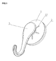
- the invention discloses a type of suction cup with a bowl-shaped framework, comprising bowl-shaped framework 1 which is deformable, cup body 2 wrapping up the framework, connecting rod 11 disposed on the back surface of the framework and passing through the cup body, bowl-shaped cup cover 3 disposed on the connecting rod and covering the back surface of the cup body, and a hooking element provided on the back surface of the cup cover and connected to the connecting rod; wherein (in a preferred embodiment) the hooking element is hook 5, connected to the connecting rod via a buckle.
- the framework has the shape of a disk and at its circumferential edge and on the back surface, annular protruding rib 12 is provided with an optimum height about 2-4 mm.
- through holes 25 are provided on the back surface of the cup body, which allow extending of the annular protruding rib to pass through and exposed on the back surface of the cup body.
- the top surface of the annular protruding rib is flush with the back surface of the cup body and the inner surface of cup cover 3 is in direct contact with the annular protruding rib.
- cup body 2 After the pressing force is removed, the residual internal force of framework 1 and cup cover 3, urge cup body 2 to restore to its original natural state, but restoring tendency is limited due to enhanced airtightness between cup body 2 and supporting surface 10. Those interactions continuously keep the cup body to be pressed against the supporting surface. Annular protruding rib 12 can effectively transfer the pressing force so that the cup will be less likely to fall off from the supporting surface.
- deformation holes 37 are provided and distributed in a circular formation to provide space for elastic deformation of the cup cover when subject to an external pressing force; otherwise the cup cover would deform very little and may even break. In the preferred embodiment, the deformation holes are elongated openings in a radial orientation.
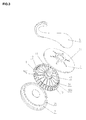
- cuts include short cuts 14 and long cuts 15.
- long cuts 15 extend from a position near the center of framework 1 to its edge, and an optimum distance between the starting position of long cuts 14 and the center of framework 1 is about 8-15 mm.
- Short cuts 14 have a length of 1/3-3/4 of that of long cut 15, and the short and long cuts (14 and 15) are arranged alternately to form a number of Y-shaped forks 101, with the bulges 13 located at both opening ends of such Y-shaped fork 101.
- Alternate arrangement of short and long cuts of the invention can enhance the strength of each Y-shaped fork, increase deformability of the framework, and facilitate the secondary injection of the plastic. Therefore, no injection opening is necessary, which is thus provided provided.
- connection part between connecting rod 11 and framework 1 is provided with reinforcing bars 102 evenly distributed along the circumference.
- the cup with a bowl-shaped framework undergoes an overall deformation under an externally applied pressing force, discharging the air between the cup and the supporting surface, generating negative pressure and forming a vacuum cavity.
- the residual internal force of both the bowl-shaped framework and the cup cover urges them to restore to their original natural state.
- the restoration tendency is limited due to the airtightness between the cup and the supporting surface so that the external air cannot enter the vacuum cavity. Therefore, the restoration tendency and the airtightness work together to ensure the cup kept continuously firmly pressed against the supporting surface.
- the cup with bowl-shaped framework of the present invention transfers the force by an elastic deformation of the cup cover.
- the suction cup of the invention can be used for hanging articles on smooth, coarse, dense, or airtight wall via a hook or basket.
- sealing gaskets 16 made of a PU material are used as seals.
- the cup body 2 and the sealing gaskets are integrally made.
- the bonding affinity of sealing gaskets 16 is higher than that of cup body 2, so that the gaskets are more easily attached to the supporting surface, enhancing the sealing effect.
- the bonding between the sealing gaskets and the cup body is good, and they are not prone to separation.
- One sealing gasket 19 and one seal ring 20 are used as the seals.
- the sealing gasket 19 is located at the center of cup body 2's adsorption surface.
- One annular groove is provided for the installation of the seal ring.
- Seal ring 20 encloses sealing gasket 19.
- the seal ring 20 and the edge of cup body 2 form a contact friction surface 30.
- a protruding ring 21 is provided for wrapping around annular protruding rib 12. Due to the protection by protruding ring 21, when protruding rib 12 is pressed by cup cover 3, it will not easily break or be otherwise damaged, ad can continuously and effectively transfer the pressing force.
- annular coarse area 22 is provided on the surface, with a smooth area 23 provided between the annular coarse area 22 and the edge of the adsorption surface, to effectively prevent entry of air and maintain the vacuum between the cup body adsorption's surface and the supporting surface.
- the annular coarse area 22 and the protruding ring 21 are located corresponding to each other.
- the annular coarse area 22 is a fully enclosed annular surface, with eroded veins. It can increase the friction force between the adsorption surface and the supporting surface, thus further increasing adsorptive force of the cup and preventing its fall-off.
- Annular coarse area 22 consists of a number coarse strips 222 arranged in a circular formation, the surface of these coarse strips is in a form of net veins. Coarse strips 222 are arranged at intervals, with a smooth area provided between two adjacent coarse strips 222.
- a pressing element is provided, which is nut sleeve 32, and a screw 11 (not shown in these figures) is used as the connecting rod.
- Hook 5 is disposed on the screw in a location between the back surface of cup cover 3 and nut sleeve 32. After the cup body is placed onto the supporting surface, nut sleeve 32 can be rotated down to pull up the screw and hence the adsorption surface of cup body 2, to increase the degree of vacuum in the vacuum cavity.
- a locating hole 33 is provided, and a corresponding locating column 51 is provided on hook 5. The locating column is inserted in the locating hole to fix hook 5 on cup cover 3.
- Hook 5 is hinged to connecting rod 11.
- the connection end of hook 5 of a cam shape.
- injection holes may be provided on the framework to facilitate its manufacture by molding injection of plastic materials, to ensure running of the plastic materials during the secondary injection in forming the cup body and wrapping the framework.
- Seals may also be directly disposed on the adsorption surface of the cup body and extend out of the surface. In case the seal rings are used as the seals, a number of seal rings of different sizes may be used and arranged concentrically positioned, enclosing center of the cup body's adsorption surface.
- the annular coarse area can also have other structures and the coarse surface can be in other forms of veins.
- the deformation holes may also be in the form of long arc openings along the circumference. The length of short cuts is 1/3-3/4 of that of the long cuts.
Landscapes
- Engineering & Computer Science (AREA)
- General Engineering & Computer Science (AREA)
- Mechanical Engineering (AREA)
- Hooks, Suction Cups, And Attachment By Adhesive Means (AREA)
Applications Claiming Priority (8)
| Application Number | Priority Date | Filing Date | Title |
|---|---|---|---|
| CN201220613987 | 2012-11-19 | ||
| CN201320107297 | 2013-03-08 | ||
| CN201320108046 | 2013-03-08 | ||
| CN 201320107296 CN203214561U (zh) | 2013-03-08 | 2013-03-08 | 一种新型吸盘 |
| CN2013104041400A CN103470611A (zh) | 2013-09-06 | 2013-09-06 | 一种吸盘罩及吸盘 |
| CN201320554911.XU CN203516411U (zh) | 2013-09-06 | 2013-09-06 | 一种新型吸盘 |
| CN201310405292.2A CN103470612B (zh) | 2013-03-08 | 2013-09-06 | 一种具有密封件的吸盘 |
| PCT/CN2013/087436 WO2014075643A1 (zh) | 2012-11-19 | 2013-11-19 | 一种碗形骨架真空吸盘 |
Publications (2)
| Publication Number | Publication Date |
|---|---|
| EP2921724A1 true EP2921724A1 (de) | 2015-09-23 |
| EP2921724A4 EP2921724A4 (de) | 2015-12-02 |
Family
ID=50730608
Family Applications (1)
| Application Number | Title | Priority Date | Filing Date |
|---|---|---|---|
| EP13854649.4A Withdrawn EP2921724A4 (de) | 2012-11-19 | 2013-11-19 | Saugnapfvorrichtung mit schalenförmigem gerüst |
Country Status (3)
| Country | Link |
|---|---|
| EP (1) | EP2921724A4 (de) |
| RU (1) | RU2592770C2 (de) |
| WO (1) | WO2014075643A1 (de) |
Cited By (1)
| Publication number | Priority date | Publication date | Assignee | Title |
|---|---|---|---|---|
| DE112017004329B4 (de) | 2016-08-31 | 2023-12-14 | Zhongshan Taili Household Products Manufacturing Co., Ltd. | Elastischer Gummikörper für einen Saugnapf |
Families Citing this family (4)
| Publication number | Priority date | Publication date | Assignee | Title |
|---|---|---|---|---|
| CN105179440A (zh) * | 2015-07-22 | 2015-12-23 | 中山市太力家庭用品制造有限公司 | 一种吸附力强的吸盘 |
| CN107228118A (zh) * | 2017-05-07 | 2017-10-03 | 曹云霞 | 一种吸盘 |
| US11203306B2 (en) | 2018-01-05 | 2021-12-21 | Xirgo Technologies, Llc | Dashboard attachment device |
| CN109469678B (zh) * | 2018-11-29 | 2023-10-10 | 东莞友颉实业有限公司 | 一种压力平衡装置及应用其的吸盘 |
Family Cites Families (10)
| Publication number | Priority date | Publication date | Assignee | Title |
|---|---|---|---|---|
| DE2124511B1 (de) * | 1971-05-18 | 1972-05-25 | Kissing & Möllmann, 5860 Iserlohn | Saugnapf mit mehreren Dichtlippen |
| SU681246A1 (ru) * | 1977-12-05 | 1979-08-25 | Московский Ордена Ленина Авиационный Институт Им. Серго Орджоникидзе | Присоска дл прикреплени изделий к поверхности |
| CN2378568Y (zh) * | 1998-11-24 | 2000-05-17 | 李进丰 | 一种改进的强力吸盘 |
| US6880790B2 (en) * | 2002-10-15 | 2005-04-19 | Gretagmacbeth, Llc | Sensor with suction cup array mount |
| CN101014775B (zh) * | 2004-05-03 | 2011-09-14 | 格特·波特斯 | 抽吸式支持装置及其配件的空吸底座 |
| DE102009017685A1 (de) * | 2009-04-16 | 2010-10-21 | Shu-Pei Huang | Saugnapfbefestiger |
| JP2011094715A (ja) * | 2009-10-30 | 2011-05-12 | Panasonic Corp | 吸盤装置 |
| CN202431729U (zh) * | 2012-01-07 | 2012-09-12 | 湖北太力家庭用品制造有限公司 | 一种新型吸盘 |
| CN103148084A (zh) * | 2013-03-08 | 2013-06-12 | 中山市太力家庭用品制造有限公司 | 一种吸盘 |
| CN103115063B (zh) * | 2013-02-07 | 2016-10-05 | 中山市太力家庭用品制造有限公司 | 一种吸盘 |
-
2013
- 2013-11-19 WO PCT/CN2013/087436 patent/WO2014075643A1/zh not_active Ceased
- 2013-11-19 EP EP13854649.4A patent/EP2921724A4/de not_active Withdrawn
- 2013-11-19 RU RU2014134368/12A patent/RU2592770C2/ru active
Cited By (1)
| Publication number | Priority date | Publication date | Assignee | Title |
|---|---|---|---|---|
| DE112017004329B4 (de) | 2016-08-31 | 2023-12-14 | Zhongshan Taili Household Products Manufacturing Co., Ltd. | Elastischer Gummikörper für einen Saugnapf |
Also Published As
| Publication number | Publication date |
|---|---|
| EP2921724A4 (de) | 2015-12-02 |
| RU2592770C2 (ru) | 2016-07-27 |
| RU2014134368A (ru) | 2016-03-20 |
| WO2014075643A1 (zh) | 2014-05-22 |
Similar Documents
| Publication | Publication Date | Title |
|---|---|---|
| US9624963B2 (en) | Vacuum suction cup having bowl-shaped framework | |
| AU2013347273B2 (en) | Vacuum suction cup having flat skeleton | |
| CN1889872B (zh) | 用于烹调器具的唇形密封件和配备有该密封件的烹调器具 | |
| US9731887B2 (en) | Rubber seal for vacuum receptacle and lid for the receptacle using the same | |
| USD659464S1 (en) | Flexible lid with hollow bulb and flared edges | |
| CN105408644B (zh) | 可拆卸真空支撑装置 | |
| EP3133035B1 (de) | Adsorptionsbecher mit trennbarem pad | |
| US8348216B2 (en) | Suction cup apparatus for attachment to porous and nonporous surfaces | |
| RU2592770C2 (ru) | Вакуумная присоска с чашеобразным каркасом | |
| USD900981S1 (en) | Urinal cake | |
| CN104884823B (zh) | 一种平骨架真空吸盘 | |
| CN104956100B (zh) | 一种碗形骨架真空吸盘 | |
| CN106080434A (zh) | 用于护线套的托架 | |
| CN103470610A (zh) | 一种带凸筋的吸盘罩及吸盘 | |
| US20140076894A1 (en) | Airtight cover | |
| KR20160102614A (ko) | 진공흡착구 | |
| CN103148084A (zh) | 一种吸盘 | |
| JP5785395B2 (ja) | 容器用開閉蓋および開閉蓋付き容器 | |
| CN207795820U (zh) | 按压式吸盘 | |
| US9022331B2 (en) | Suction device | |
| CN219858788U (zh) | 一种减少垃圾桶顶部压圈脏污的垃圾桶 | |
| CN211533893U (zh) | 用于烹饪器具的密封圈组件、锅盖和烹饪器具 | |
| CN205978026U (zh) | 吸盘式板夹 | |
| CN211722866U (zh) | 一种壶底可拆卸的咖啡壶 | |
| KR102072494B1 (ko) | 밀봉용기 |
Legal Events
| Date | Code | Title | Description |
|---|---|---|---|
| PUAI | Public reference made under article 153(3) epc to a published international application that has entered the european phase |
Free format text: ORIGINAL CODE: 0009012 |
|
| 17P | Request for examination filed |
Effective date: 20150617 |
|
| AK | Designated contracting states |
Kind code of ref document: A1 Designated state(s): AL AT BE BG CH CY CZ DE DK EE ES FI FR GB GR HR HU IE IS IT LI LT LU LV MC MK MT NL NO PL PT RO RS SE SI SK SM TR |
|
| AX | Request for extension of the european patent |
Extension state: BA ME |
|
| RA4 | Supplementary search report drawn up and despatched (corrected) |
Effective date: 20151029 |
|
| RIC1 | Information provided on ipc code assigned before grant |
Ipc: F16B 47/00 20060101AFI20151023BHEP |
|
| DAX | Request for extension of the european patent (deleted) | ||
| 17Q | First examination report despatched |
Effective date: 20160714 |
|
| 17Q | First examination report despatched |
Effective date: 20160805 |
|
| STAA | Information on the status of an ep patent application or granted ep patent |
Free format text: STATUS: THE APPLICATION IS DEEMED TO BE WITHDRAWN |
|
| 18D | Application deemed to be withdrawn |
Effective date: 20200603 |