EP2921765B1 - Lichtbandsystem - Google Patents
Lichtbandsystem Download PDFInfo
- Publication number
- EP2921765B1 EP2921765B1 EP15159543.6A EP15159543A EP2921765B1 EP 2921765 B1 EP2921765 B1 EP 2921765B1 EP 15159543 A EP15159543 A EP 15159543A EP 2921765 B1 EP2921765 B1 EP 2921765B1
- Authority
- EP
- European Patent Office
- Prior art keywords
- conductor
- lighting system
- strip lighting
- electrical
- electrical conductor
- Prior art date
- Legal status (The legal status is an assumption and is not a legal conclusion. Google has not performed a legal analysis and makes no representation as to the accuracy of the status listed.)
- Not-in-force
Links
- 239000004020 conductor Substances 0.000 claims description 89
- 238000006073 displacement reaction Methods 0.000 description 3
- 239000000945 filler Substances 0.000 description 2
- 230000006378 damage Effects 0.000 description 1
- 230000001419 dependent effect Effects 0.000 description 1
- 238000010586 diagram Methods 0.000 description 1
- 229910052736 halogen Inorganic materials 0.000 description 1
- 150000002367 halogens Chemical class 0.000 description 1
- 238000009413 insulation Methods 0.000 description 1
- 239000011159 matrix material Substances 0.000 description 1
- 238000004080 punching Methods 0.000 description 1
- 230000002441 reversible effect Effects 0.000 description 1
- 238000000926 separation method Methods 0.000 description 1
Images



Classifications
-
- H—ELECTRICITY
- H01—ELECTRIC ELEMENTS
- H01R—ELECTRICALLY-CONDUCTIVE CONNECTIONS; STRUCTURAL ASSOCIATIONS OF A PLURALITY OF MUTUALLY-INSULATED ELECTRICAL CONNECTING ELEMENTS; COUPLING DEVICES; CURRENT COLLECTORS
- H01R4/00—Electrically-conductive connections between two or more conductive members in direct contact, i.e. touching one another; Means for effecting or maintaining such contact; Electrically-conductive connections having two or more spaced connecting locations for conductors and using contact members penetrating insulation
- H01R4/24—Connections using contact members penetrating or cutting insulation or cable strands
- H01R4/2416—Connections using contact members penetrating or cutting insulation or cable strands the contact members having insulation-cutting edges, e.g. of tuning fork type
- H01R4/2445—Connections using contact members penetrating or cutting insulation or cable strands the contact members having insulation-cutting edges, e.g. of tuning fork type the contact members having additional means acting on the insulation or the wire, e.g. additional insulation penetrating means, strain relief means or wire cutting knives
-
- F—MECHANICAL ENGINEERING; LIGHTING; HEATING; WEAPONS; BLASTING
- F21—LIGHTING
- F21V—FUNCTIONAL FEATURES OR DETAILS OF LIGHTING DEVICES OR SYSTEMS THEREOF; STRUCTURAL COMBINATIONS OF LIGHTING DEVICES WITH OTHER ARTICLES, NOT OTHERWISE PROVIDED FOR
- F21V21/00—Supporting, suspending, or attaching arrangements for lighting devices; Hand grips
- F21V21/002—Supporting, suspending, or attaching arrangements for lighting devices; Hand grips making direct electrical contact, e.g. by piercing
-
- F—MECHANICAL ENGINEERING; LIGHTING; HEATING; WEAPONS; BLASTING
- F21—LIGHTING
- F21S—NON-PORTABLE LIGHTING DEVICES; SYSTEMS THEREOF; VEHICLE LIGHTING DEVICES SPECIALLY ADAPTED FOR VEHICLE EXTERIORS
- F21S4/00—Lighting devices or systems using a string or strip of light sources
- F21S4/20—Lighting devices or systems using a string or strip of light sources with light sources held by or within elongate supports
- F21S4/28—Lighting devices or systems using a string or strip of light sources with light sources held by or within elongate supports rigid, e.g. LED bars
-
- F—MECHANICAL ENGINEERING; LIGHTING; HEATING; WEAPONS; BLASTING
- F21—LIGHTING
- F21S—NON-PORTABLE LIGHTING DEVICES; SYSTEMS THEREOF; VEHICLE LIGHTING DEVICES SPECIALLY ADAPTED FOR VEHICLE EXTERIORS
- F21S4/00—Lighting devices or systems using a string or strip of light sources
-
- F—MECHANICAL ENGINEERING; LIGHTING; HEATING; WEAPONS; BLASTING
- F21—LIGHTING
- F21Y—INDEXING SCHEME ASSOCIATED WITH SUBCLASSES F21K, F21L, F21S and F21V, RELATING TO THE FORM OR THE KIND OF THE LIGHT SOURCES OR OF THE COLOUR OF THE LIGHT EMITTED
- F21Y2115/00—Light-generating elements of semiconductor light sources
- F21Y2115/10—Light-emitting diodes [LED]
-
- H—ELECTRICITY
- H01—ELECTRIC ELEMENTS
- H01R—ELECTRICALLY-CONDUCTIVE CONNECTIONS; STRUCTURAL ASSOCIATIONS OF A PLURALITY OF MUTUALLY-INSULATED ELECTRICAL CONNECTING ELEMENTS; COUPLING DEVICES; CURRENT COLLECTORS
- H01R13/00—Details of coupling devices of the kinds covered by groups H01R12/70 or H01R24/00 - H01R33/00
- H01R13/66—Structural association with built-in electrical component
- H01R13/70—Structural association with built-in electrical component with built-in switch
- H01R13/703—Structural association with built-in electrical component with built-in switch operated by engagement or disengagement of coupling parts, e.g. dual-continuity coupling part
- H01R13/7031—Shorting, shunting or bussing of different terminals interrupted or effected on engagement of coupling part, e.g. for ESD protection, line continuity
-
- H—ELECTRICITY
- H01—ELECTRIC ELEMENTS
- H01R—ELECTRICALLY-CONDUCTIVE CONNECTIONS; STRUCTURAL ASSOCIATIONS OF A PLURALITY OF MUTUALLY-INSULATED ELECTRICAL CONNECTING ELEMENTS; COUPLING DEVICES; CURRENT COLLECTORS
- H01R2103/00—Two poles
-
- H—ELECTRICITY
- H01—ELECTRIC ELEMENTS
- H01R—ELECTRICALLY-CONDUCTIVE CONNECTIONS; STRUCTURAL ASSOCIATIONS OF A PLURALITY OF MUTUALLY-INSULATED ELECTRICAL CONNECTING ELEMENTS; COUPLING DEVICES; CURRENT COLLECTORS
- H01R25/00—Coupling parts adapted for simultaneous co-operation with two or more identical counterparts, e.g. for distributing energy to two or more circuits
- H01R25/14—Rails or bus-bars constructed so that the counterparts can be connected thereto at any point along their length
- H01R25/142—Their counterparts
-
- H—ELECTRICITY
- H01—ELECTRIC ELEMENTS
- H01R—ELECTRICALLY-CONDUCTIVE CONNECTIONS; STRUCTURAL ASSOCIATIONS OF A PLURALITY OF MUTUALLY-INSULATED ELECTRICAL CONNECTING ELEMENTS; COUPLING DEVICES; CURRENT COLLECTORS
- H01R25/00—Coupling parts adapted for simultaneous co-operation with two or more identical counterparts, e.g. for distributing energy to two or more circuits
- H01R25/16—Rails or bus-bars provided with a plurality of discrete connecting locations for counterparts
- H01R25/161—Details
- H01R25/162—Electrical connections between or with rails or bus-bars
Definitions
- the invention relates to a lighting system with a busbar and a light module.
- a lighting system which has a busbar and lighting modules with light sources therein.
- an electrical line runs to power the light sources.
- the lighting modules are mechanically connected to the busbar, so that they are arranged to operate on the latter hanging.
- As part of the mechanical connection and the electrical connection between the light sources of the lighting modules and the busbar is made.
- a corresponding electrical circuit is outlined.
- This comprises a two-phase or two-pole conductor arrangement formed in the busbar, which extends along the longitudinal axis of the busbar.
- the light sources of the light modules in this example are 12 V low-voltage halogen lamps; These are connected in parallel to the two poles.
- the conductor arrangement is connected to a current source in the form of a constant voltage source.
- the so designed busbar represents a "classic" low-voltage busbar.
- LED light sources are gaining increasing market acceptance.
- LED light source is here meant a light source having at least one LED.
- an LED light source may have a plurality of LEDs arranged along a row or arranged in the form of a matrix.
- an LED light source can have at least one printed circuit board on which the at least one LED is arranged.
- LED lighting module here refers to a lighting module which has an LED light source as the light source.
- connection piece comprises a punching element with which the supply line is interrupted when connecting the LED light.
- an LED system with an LED module is known, which can be connected by means of a socket element to an electrical cable.
- the socket element has for this purpose two insulation displacement terminals and a separator.
- a similar system is also from the Scriptures US 2005/0207151 A1 known.
- a LED string of lights is also from the font US 2010/0128481 A1 known.
- the invention has for its object to provide a corresponding improved lighting system;
- the lighting system should be particularly suitable for LED lighting modules.
- a lighting strip system which has a busbar with at least one electrical conductor, and a lighting module with an electrical load; the consumer is connected to the power supply via an electrical connection to the electrical conductor.
- the light band system has a connection element which is designed to sever or interrupt the electrical conductor to establish the electrical connection, so that two conductor end pieces are formed and connect the two conductor end pieces instead via the load.
- the consumer which may in particular be an LED light source, can be connected in series in the electrical conductor.
- the lighting system is particularly suitable as a lighting system for LED lighting modules.
- connection element is arranged on the lighting module. This allows easy handling.
- connection element has at least one cutting element for severing the electrical conductor.
- the connection element has at least one cutting element for severing the electrical conductor.
- the electrical conductor has a portion which is aligned parallel to the longitudinal axis of the bus bar, wherein the electrical connection is arranged in the section.
- the light module can be arranged or mounted on the busbar at any point along the longitudinal axis for operation.
- the conductor has a partial region, the design being such that the partial region can be moved by the connection element in such a way that it separates from the remaining conductor, in particular by displacement, displacement or rotation and thus the two conductor end pieces are formed.
- the light module can be reversibly mounted on the busbar for operation.
- the portion is aligned transversely, in particular perpendicular to the longitudinal axis of the busbar running.
- the electrical conductor further comprises at least one further partial region, which is designed analogously to the first-mentioned partial region. In this way, it can be achieved that different possible connection points along the longitudinal axis are available for mounting the lighting module.
- the light band system is designed in such a way that when the connection element is separated from the electrical conductor, the two conductor end pieces are automatically connected again electrically, for example by a spring element. In this way, the lighting system can continue to operate after disassembly of the light module readily.
- the consumer is a light source, in particular an LED light source.
- the light band system further comprises a constant current source for powering the light module.
- the electrical conductor has a return line section which extends along the longitudinal axis of the bus bar, wherein no light sources, in particular no consumer is connected in the return line section.
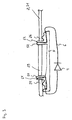
- Fig. 1 is a sketch of the principle of a lighting system according to the invention shown.
- the sketch shows a vertical longitudinal section.
- the lighting strip system comprises a busbar 1 with at least one electrical conductor 2.
- the busbar 1 is preferably elongate, so that it extends along a longitudinal axis L.
- the busbar 1 may be U-shaped, so that the two corresponding U-legs extend downwards, the electrical conductor 2 extending in an inner region of the busbar 1 circumscribed by the U-shape is arranged.
- the light band system comprises a lighting module 3 with an electrical load 4.
- the consumer may be a light source, in particular an LED light source 4, so that the lighting module 3 is an LED lighting module.
- the light module 3 is connectable to the busbar 1, in particular configured to be mechanically and electrically connected to the busbar 1.
- the light module 3 is elongated, wherein it, with its longitudinal axis, when it is connected as intended to the busbar 1, parallel to the busbar 1 and to the longitudinal axis L extends.
- the lighting module 3 is shorter along the longitudinal axis L considered as the busbar 1.
- the lighting module 3 may have a length which is smaller than half the length of the busbar 1.
- the lighting system also comprises at least one further lighting module 3 ', 3rd ", which is designed in particular analogously, for example structurally identical to the first-mentioned lighting module 3, wherein the at least one further lighting module 3 ', 3" in particular analogous to the first-mentioned lighting module 3 to the busbar 1 is connectable.
- the design is preferably such that the lighting module 3 and the at least one further lighting module 3 ', 3 "are connectable to the busbar 1 such that the lighting modules 3, 3', 3" form a row extending in the longitudinal direction L.
- the lighting module 3 or the at least one further lighting module 3 ', 3 " can also be, for example, an LED spotlight.
- the consumer is connectable to the power supply via an electrical connection to the electrical conductor 2.
- the design is such that in one step, the light module 3 mechanically arrange on the busbar 1 and can be said electrical connection.
- connection element 5 which can be arranged, for example, on the light-emitting module 3.
- Fig. 3 is a possible embodiment of the connection element 5 schematically outlined.
- the connection element 5 is configured to sever or interrupt the electrical conductor 2 for the purpose of establishing the electrical connection, so that two conductor end pieces 25, 26 are formed and the two conductor end pieces 25, 26 instead connect via the LED light source 4.
- the current can be passed through the LED light source 4 and then "feed" again into the busbar 1.
- the LED light source 4 can be switched electrically in series into the conductor 2.
- the lighting system preferably further comprises a constant current source 7, that is, for example, a corresponding operating device or a converter for powering the lighting module 3 or the consumer, ie in particular the LED light source 4.
- a constant current source 7 that is, for example, a corresponding operating device or a converter for powering the lighting module 3 or the consumer, ie in particular the LED light source 4.
- connection element 5 may have at least one cutting element 51, 52 for cutting through the electrical conductor 2.
- the connecting element 5, a first cutting element 51 and a second cutting element 52 wherein the design is such that for cutting the conductor 2 by the two said cutting elements 51, 52, a piece 29 of the conductor 2 is cut out.
- the LED light source 4 is connected in a conductor portion 6, the conductor portion 6 having a first conductor portion end portion 61 and a second conductor portion end portion 62 and electrically connecting the first conductor end portion 25 to the first conductor portion to make the electrical connection. End portion 61 is connected and the second conductor end 26 with the second conductor portion end portion 62nd
- the first conductor portion end portion 61 is formed directly adjacent to the first cutting element 51 or arranged on the latter; the same applies to the second conductor section end region 62 and the second cutting element 52.
- the conductor section 6 with the LED light source 4 extends correspondingly at least partially in the lighting module 3.
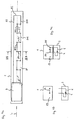
- Fig. 2a a horizontal longitudinal section sketch is sketched to a corresponding embodiment.
- Sketched is the busbar 1 and the electrical conductor 2 therein, which here has a portion 21 which is aligned parallel to the longitudinal axis L of the busbar 1 extending.
- Fig. 2b shows a corresponding vertical longitudinal section sketch at the level of said portion 21, wherein the lighting module 3 before connection to the busbar 1, that is from the latter is still positioned separated; in Fig. 2c is a corresponding sketch after mounting the light module 3 on the busbar 1 shown.
- the section 21 of the conductor 2 can - as in Fig. 2b indicated - extend without interruption.
- the section 21 of the conductor 2 is interrupted by means of the connection element 5 as described above, so that the two conductor end pieces 25, 26 are formed and the latter then via the LED light source. 4 electrically connected again.
- Fig. 2c is the cut out by the connecting element 5 piece 29 of the conductor 2 indicated by two slashes.
- FIGS. 4a to 4c is outlined another embodiment, wherein the reference numerals are used in an analogous manner. Unless stated otherwise, the above statements also apply to the second embodiment.
- Fig. 4a again shows a horizontal longitudinal section sketch.
- the conductor 2 has in this example a portion 24 which can be moved by the connection element 5 so that it separates from the remaining conductor 2 and thereby the two conductor end pieces 25, 26 are formed.
- it is preferably the portion 24 transversely aligned, in particular perpendicular to the longitudinal axis L of the busbar 1 extending.
- a corresponding portion 24 may also be formed parallel to the longitudinal axis L.
- connection element 5 can advantageously be arranged correspondingly rotatable or displaceable.
- the conductor 2 has a "displaced" structure, such that it extends with a plurality of sections 211 along a first straight line g1 and with a plurality of further sections 212 along a second straight line g2 parallel to the latter, the partial area 24 electrically connects one of the sections 211 with one of the further sections 212.
- the two mentioned straight lines g1, g2 preferably extend parallel to the longitudinal axis L.
- the conductor 2 preferably also has at least one further subarea 24 ', which in particular is analogous to the first subarea 24 is designed.
- the several sections 211 are alternately connected to the further several sections 212 by the partial area 24 and the at least one further partial area 24 ', so that overall a meander-shaped conductor section of the conductor 2 is formed which is parallel to the main extension Longitudinal axis L extends.
- the portion 24 forms a "filler" or a component which is formed separately from the remaining conductor 2.
- the portion 24 is prepared, so to speak for a separation from the conductor 2; It can be achieved that the portion 24 can be separated from the remaining conductor 2 without mechanical destruction.
- resilient contact areas may be formed, which in Fig. 4a symbolically indicated by small circles.
- Fig. 4b a corresponding vertical sketch is shown normal to the longitudinal axis L at the level of the portion 24, in turn with the light module 3 to be connected to the busbar 1.
- Fig. 4c shows the situation with the connected or mounted light module 3. Again, in the connected state, the original conductor 2 between the twoêtend constitutionalen 25, 26 is separated, as in Fig. 4c indicated by the two slashes; instead, the two conductor end pieces 25, 26 are connected via the LED light source 4 or the conductor section 6 with the LED light source 4 connected therein.
- the said movement of the portion 24 may be realized, for example, by displacing, shifting or turning or pivoting. For example, it can thus be provided that the filler or the portion 24 is unscrewed or moved laterally.
- the lighting module 3 can be mounted on the busbar 1 and electrically connected to any of the subregions 24, 24', so that along the longitudinal axis L several possible connection points for mounting the Illuminated module 3 are formed.
- the portion 21 is cut, there is basically no restriction with respect to the position along the Longitudinal axis at which the light emitting module is mounted on the conductor rail 1 L 3.
- the possible mounting locations are defined by the transverse portions 24, 24 'of the conductor 2.
- the design can advantageously be such that when the connection element 5 is separated from the electrical conductor 2, the two conductor end pieces 25, 26 are automatically electrically connected again, for example by a spring element.
- the sub-area 24 is moved back to its original position, so that the original course of the conductor 2 is restored.
- the light band system can thus continue to operate in this embodiment after disassembly of the light module 3 without further notice. In other words, a reversible arrangement of the light-emitting module 3 on the busbar 1 is made possible.
- the electrical conductor 2 preferably has a return line section 23 which extends along the longitudinal axis L of the busbar 1, wherein no light source, in particular no consumer is connected in the return line section 23.
- the constant current source 7 is disposed at a first end portion of the conductor 2 with respect to the longitudinal axis L ;
- the conductor 2 preferably has a connection section 23 which connects the section 21 or, in the case of the second example, a section in which the section 24 is located to the return section 23.
Landscapes
- Engineering & Computer Science (AREA)
- General Engineering & Computer Science (AREA)
- Non-Portable Lighting Devices Or Systems Thereof (AREA)
Description
- Die Erfindung betrifft ein Lichtbandsystem mit einer Stromschiene und einem Leuchtmodul.
- Aus dem Stand der Technik ist ein Lichtbandsystem bekannt, das eine Stromschiene und Leuchtmodule mit darin befindlichen Lichtquellen aufweist. In der Stromschiene verläuft eine elektrische Leitung zur Stromversorgung der Lichtquellen. Zur Montage werden die Leuchtmodule mit der Stromschiene mechanisch verbunden, so dass sie zum Betrieb an Letzterer hängend angeordnet sind. Im Rahmen der mechanischen Verbindung wird auch die elektrische Verbindung zwischen den Lichtquellen der Leuchtmodule und der Stromschiene hergestellt.
- In
Fig. 5 ist eine entsprechende elektrische Schaltung skizziert. Diese umfasst eine in der Stromschiene ausgebildete zweiphasige bzw. zweipolige Leiteranordnung, die sich entlang der Längsachse der Stromschiene erstreckt. Bei den Lichtquellen der Leuchtmodule handelt es sich in diesem Beispiel um 12 V Niedervolt-Halogenlampen; diese sind parallel an die beiden Pole angeschlossen. Zur elektrischen Verbindung der Lichtquellen an die Leiteranordnung in der Stromschiene dienen hierbei Stecker-Buchsen-Systeme. An einem Endbereich ist die Leiteranordnung mit einer Stromquelle in Form einer Konstantspannungs-Quelle verbunden. Die so gestaltete Stromschiene stellt eine "klassische" Niedervolt-Stromschiene dar. - In letzter Zeit setzen sich auf dem Markt zunehmend LED-Lichtquellen (LED: Licht emittierende Diode) durch. Mit "LED-Lichtquelle" sei hier eine Lichtquelle bezeichnet, die wenigstens eine LED aufweist. Beispielsweise kann eine LED-Lichtquelle mehrere LEDs aufweisen, die entlang einer Reihe angeordnet sind oder die in Form einer Matrix angeordnet sind. Weiterhin kann eine LED-Lichtquelle wenigstens eine Platine aufweisen, auf der die wenigstens eine LED angeordnet ist. Mit "LED-Leuchtmodul" sei hier ein Leuchtmodul bezeichnet, das als Lichtquelle eine LED-Lichtquelle aufweist.
- Zur Stromversorgung von LED-Lichtquellen haben sich Konstantstrom-Quellen durchgesetzt, die die LED-Lichtquellen, wie in
Fig. 6 skizziert, in Serienschaltung an konstantem Strom betreiben. Eine klassische Niedervolt-Stromquelle gemäßFig. 5 mit einem entsprechenden Stecker-Buchsen-System kann zur Herstellung einer solchen Reihenschaltung daher nicht verwendet werden. - Aus der
DE 10 2007 057 765 A1 ist ein LED-System mit einer Versorgungsleitung und einer LED-Leuchte bekannt, die mit Hilfe eines Anschlussstücks elektrisch an der Versorgungsleitung angeschlossen werden kann. Das Anschlussstück umfasst hierzu ein Stanzelement, mit dem die Versorgungsleitung beim Anschließen der LED-Leuchte unterbrochen wird. - Aus der
WO 2007/047398 A2 ist ein LED-System mit einem LED-Modul bekannt, das mit Hilfe eines Fassungselements an ein elektrischen Kabel angeschlossen werden kann. Das Fassungselement weist hierzu zwei Schneidklemmen und ein Trennelement auf. Ein insoweit ähnliches System ist auch aus der SchriftUS 2005/0207151 A1 bekannt. Eine LED-Lichterkette ist auch aus der SchriftUS 2010/0128481 A1 bekannt. - Der Erfindung liegt die Aufgabe zugrunde, ein entsprechendes verbessertes Lichtbandsystem anzugeben; insbesondere soll sich das Lichtbandsystem besonders für LED-Leuchtmodule eignen.
- Diese Aufgabe wird gemäß der Erfindung mit dem in dem unabhängigen Anspruch genannten Gegenstand gelöst. Besondere Ausführungsarten der Erfindung sind in den abhängigen Ansprüchen angegeben.
- Gemäß der Erfindung ist ein Lichtbandsystem vorgesehen, das eine Stromschiene mit mindestens einem elektrischen Leiter aufweist, sowie ein Leuchtmodul mit einem elektrischen Verbraucher; der Verbraucher ist dabei zur Stromversorgung über eine elektrische Verbindung mit dem elektrischen Leiter verbindbar. Weiterhin weist das Lichtbandsystem ein Anschlusselement auf, das dazu ausgestaltet ist, zur Herstellung der elektrischen Verbindung den elektrischen Leiter zu durchtrennen bzw. zu unterbrechen, so dass zwei Leiterendstücke gebildet sind und die zwei Leiterendstücke stattdessen über den Verbraucher zu verbinden.
- Durch diese Gestaltung lässt sich der Verbraucher, bei dem es sich insbesondere um eine LED-Lichtquelle handeln kann, in den elektrischen Leiter in Reihe schalten. Auf diese Weise eignet sich das Leuchtbandsystem besonders als Lichtbandsystem für LED-Leuchtmodule.
- Vorzugsweise ist das Anschlusselement an dem Leuchtmodul angeordnet. Hierdurch ist eine einfache Handhabbarkeit ermöglicht.
- Vorzugsweise weist das Anschlusselement wenigstens ein Schneidelement zum Durchtrennen des elektrischen Leiters auf. Hierdurch ist unter Zuhilfenahme weniger Bauteile ein effektives Durchtrennen des Leiters ermöglicht.
- Vorzugsweise weist der elektrische Leiter einen Abschnitt auf, der parallel zu der Längsachse der Stromschiene verlaufend ausgerichtet ist, wobei die die elektrische Verbindung in dem Abschnitt angeordnet ist. Hierdurch lässt sich besonders geeignet erzielen, dass das Leuchtmodul zum Betrieb an einer beliebigen Stelle entlang der Längsachse an der Stromschiene angeordnet bzw. montiert werden kann.
- Vorzugsweise weist der Leiter einen Teilbereich auf, wobei die Gestaltung derart ist, dass der Teilbereich durch das Anschlusselement so bewegt werden kann, dass er sich von dem restlichen Leiter trennt, insbesondere durch ein Verdrängen, Verschieben oder Drehen und hierdurch die zwei Leiterendstücke gebildet sind. Auf diese Weise lässt sich insbesondere erzielen, dass das Leuchtmodul zum Betrieb reversibel an der Stromschiene montiert werden kann. Vorzugsweise ist der Teilbereich dabei quer, insbesondere senkrecht zu der Längsachse der Stromschiene verlaufend ausgerichtet.
- Vorzugsweise weist der elektrische Leiter weiterhin wenigstens einen weiteren Teilbereich auf, der analog zu dem zuerst genannten Teilbereich gestaltet ist. Auf diese Weise lässt sich erzielen, dass für die Montage des Leuchtmoduls unterschiedliche mögliche Anbindungsstellen entlang der Längsachse zur Verfügung stehen.
- Erfindungsgemäß ist das Lichtbandsystem derart gestaltet, dass bei einem Trennen des Anschlusselements von dem elektrischen Leiter die zwei Leiterendstücke selbsttätig wieder elektrisch verbunden werden, beispielsweise durch ein Federelement. Auf diese Weise lässt sich das Lichtbandsystem nach einer Demontage des Leuchtmoduls ohne Weiteres weiterbetrieben.
- Vorzugsweise ist der Verbraucher eine Lichtquelle, insbesondere eine LED-Lichtquelle.
- Vorzugsweise weist das Lichtbandsystem weiterhin eine Konstantstrom-Quelle zur Stromversorgung des Leuchtmoduls auf.
- Vorzugsweise weist der elektrische Leiter einen Rückleitungsabschnitt auf, der sich entlang der Längsachse der Stromschiene erstreckt, wobei keine Lichtquellen, insbesondere kein Verbraucher in den Rückleitungsabschnitt geschaltet ist.
- Die Erfindung wird im Folgenden anhand eines Ausführungsbeispiels und mit Bezug auf die Zeichnungen näher erläutert. Es zeigen:
- Fig. 1
- eine vertikale Längsschnitt-Skizze zum Prinzip eines erfindungsgemäßen Lichtbandsystems,
- Fig. 2a
- eine horizontale Längsschnitt-Skizze zu einem ersten Ausführungsbeispiel,
- Fig. 2b
- eine entsprechende vertikale Längsschnitt-Skizze mit einem an die Stromschiene anzuschließenden LED-Leuchtmodul,
- Fig. 2c
- eine entsprechende Skizze mit angeschlossenem LED-Leuchtmodul,
- Fig. 3
- eine Prinzip-Skizze zu einer Ausführung des Anschlusselements,
- Fig. 4a
- eine horizontale Längsschnitt-Skizze zu einem zweiten Ausführungsbeispiel,
- Fig. 4b
- eine entsprechende vertikale Querschnitt-Skizze mit einem an die Stromschiene anzuschließenden LED-Leuchtmodul,
- Fig. 4c
- eine entsprechende Skizze mit angeschlossenem LED-Leuchtmodul,
- Fig. 5
- eine Skizze zu einer Schaltung einer klassischen Niedervolt-Stromschiene und
- Fig. 6
- eine Skizze zu einer Reihenschaltung von LEDs.
- In
Fig. 1 ist eine Skizze zum Prinzip eines erfindungsgemäßen Lichtbandsystems gezeigt. Die Skizze zeigt dabei einen vertikalen Längsschnitt. Das Lichtbandsystem umfasst eine Stromschiene 1 mit mindestens einem elektrischen Leiter 2. Die Stromschiene 1 ist vorzugsweise länglich, so dass sie sich entlang einer Längsachse L erstreckt. Beispielsweise kann die Stromschiene 1 in einem Schnitt normal zu der Längsachse L betrachtet U-förmig gestaltet sein, so dass sich die beiden entsprechenden U-Schenkel nach unten erstrecken, wobei der elektrische Leiter 2 in einem durch die U-Form umschriebenen Innenbereich der Stromschiene 1 angeordnet ist. - Weiterhin umfasst das Lichtbandsystem ein Leuchtmodul 3 mit einem elektrischen Verbraucher 4. Bei dem Verbraucher kann es sich um eine Lichtquelle, insbesondere um eine LED-Lichtquelle 4 handeln, so dass es sich bei dem Leuchtmodul 3 um ein LED-Leuchtmodul handelt. Das Leuchtmodul 3 ist mit der Stromschiene 1 verbindbar, insbesondere dazu ausgestaltet, mit der Stromschiene 1 mechanisch und elektrisch verbunden zu werden. Vorzugsweise ist das Leuchtmodul 3 länglich geformt, wobei es sich, mit seiner Längsachse, wenn es wie vorgesehen mit der Stromschiene 1 verbunden ist, parallel zu der Stromschiene 1 bzw. zu der Längsachse L erstreckt.
- Insbesondere ist das Leuchtmodul 3 entlang der Längsachse L betrachtet kürzer als die Stromschiene 1. Beispielsweise kann das Leuchtmodul 3 eine Länge aufweisen, die kleiner ist als die Hälfte der Länge der Stromschiene 1. Vorzugsweise umfasst das Lichtbandsystem außerdem wenigstens ein weiteres Leuchtmodul 3', 3", das insbesondere analog, beispielsweise baugleich zu dem zuerst genannten Leuchtmodul 3 gestaltet ist, wobei das wenigstens eine weitere Leuchtmodul 3', 3" insbesondere analog zu dem zuerst genannten Leuchtmodul 3 mit der Stromschiene 1 verbindbar ist. Dabei ist die Gestaltung vorzugsweise so, dass das Leuchtmodul 3 und das wenigstens eine weitere Leuchtmodul 3', 3" so mit der Stromschiene 1 verbindbar sind, dass die Leuchtmodule 3, 3', 3 " eine in der Längsrichtung L verlaufende Reihe bilden.
- Bei dem Leuchtmodul 3 bzw. dem wenigstens einen weiteren Leuchtmodul 3', 3" kann es sich jedoch auch beispielsweise um einen LED-Strahler handeln.
- Der Verbraucher, hier am Beispiel der LED-Lichtquelle 4 betrachtet, ist zur Stromversorgung über eine elektrische Verbindung mit dem elektrischen Leiter 2 verbindbar. Vorzugsweise ist die Gestaltung so, dass sich in einem Arbeitsschritt das Leuchtmodul 3 mechanisch an der Stromschiene 1 anordnen und die genannte elektrische Verbindung herstellen lässt.
- Weiterhin weist das Lichtbandsystem ein Anschlusselement 5 auf, das beispielsweise an dem Leuchtmodul 3 angeordnet sein kann. In
Fig. 3 ist eine mögliche Ausführung des Anschlusselements 5 schematisch skizziert. Das Anschlusselement 5 ist dazu ausgestaltet, zur Herstellung der elektrischen Verbindung den elektrischen Leiter 2 zu durchtrennen bzw. zu unterbrechen, so dass zwei Leiterendstücke 25, 26 gebildet sind und die zwei Leiterendstücke 25, 26 stattdessen über die LED-Lichtquelle 4 zu verbinden. - Auf diese Weise lässt sich also der Strom über die LED-Lichtquelle 4 leiten und danach wieder in die Stromschiene 1 "einspeisen".
- Insbesondere lässt sich auf diese Weise die LED-Lichtquelle 4 elektrisch in Reihe in den Leiter 2 schalten. Durch diese Gestaltung lässt sich somit erzielen, dass mit lediglich einer Stromquelle, also beispielsweise lediglich einem Betriebsgerät mehrere LED-Lichtquellen bzw. mehrere LED-Leuchtmodule und/oder LED-Strahler mit Strom versorgt werden.
- Dementsprechend weist das Lichtbandsystem vorzugsweise weiterhin eine Konstantstrom-Quelle 7, also beispielsweise ein entsprechendes Betriebsgerät bzw. einen Konverter zur Stromversorgung des Leuchtmoduls 3 bzw. des Verbrauchers, also insbesondere der LED-Lichtquelle 4 auf.
- Beispielsweise kann das Anschlusselement 5 wenigstens ein Schneidelement 51, 52 zum Durchtrennen des elektrischen Leiters 2 aufweisen. In dem in
Fig. 3 skizzierten Beispiel weist das Anschlusselement 5 ein erstes Schneidelement 51 und ein zweites Schneidelement 52 auf, wobei die Gestaltung so ist, dass zum Durchtrennen des Leiters 2 durch die beiden genannten Schneidelemente 51, 52 ein Stück 29 des Leiters 2 herausgeschnitten wird. Weiterhin ist bei diesem Beispiel die LED-Lichtquelle 4 in einen Leiterabschnitt 6 geschaltet, wobei der Leiterabschnitt 6 einen ersten Leiterabschnitt-Endbereich 61 und einen zweiten Leiterabschnitt-Endbereich 62 aufweist und zum Herstellen der elektrischen Verbindung das erste Leiterendstück 25 elektrisch mit dem ersten Leiterabschnitt-Endbereich 61 verbunden wird und das zweite Leiterendstück 26 mit dem zweiten Leiterabschnitt-Endbereich 62. - Vorzugsweise ist dabei der erste Leiterabschnitt-Endbereich 61 unmittelbar dem ersten Schneidelement 51 benachbart ausgebildet oder an Letzterem angeordnet; analoges gilt für den zweiten Leiterabschnitt-Endbereich 62 und das zweite Schneidelement 52.
- Der Leiterabschnitt 6 mit der LED-Lichtquelle 4 erstreckt sich dabei dementsprechend zumindest teilweise in dem Leuchtmodul 3.
- In
Fig. 2a ist eine horizontale Längsschnitt-Skizze zu einem entsprechenden Ausführungsbeispiel skizziert. Skizziert ist die Stromschiene 1 und der darin befindliche elektrische Leiter 2, der hier einen Abschnitt 21 aufweist, der parallel zu der Längsachse L der Stromschiene 1 verlaufend ausgerichtet ist.Fig. 2b zeigt eine entsprechende vertikale Längsschnitt-Skizze auf Höhe des genannten Abschnitts 21, wobei das Leuchtmodul 3 vor Verbindung mit der Stromschiene 1, also von Letzterer noch separiert positioniert ist; inFig. 2c ist eine entsprechende Skizze nach Montieren des Leuchtmoduls 3 an der Stromschiene 1 gezeigt. - Bevor das Leuchtmodul 3 mit der Stromschiene 1 verbunden ist, kann sich der Abschnitt 21 des Leiters 2 - wie in
Fig. 2b angedeutet - ohne Unterbrechung erstrecken. Zur Herstellung der elektrischen Verbindung zwischen der LED-Lichtquelle 4 und dem Leiter 2 wird der Abschnitt 21 des Leiters 2 mithilfe des Anschlusselements 5 wie oben beschrieben unterbrochen, so dass die beiden Leiterendstücke 25, 26 gebildet sind und Letztere dann über die LED-Lichtquelle 4 wieder elektrisch miteinander verbunden. InFig. 2c ist das durch das Anschlusselement 5 herausgeschnittene Stück 29 des Leiters 2 durch zwei Schrägstriche angedeutet. - In den
Figuren 4a bis 4c ist ein weiteres Ausführungsbeispiel skizziert, wobei die Bezugszeichen in analoger Weise gebraucht sind. Soweit nicht anders angegeben, gelten die obigen Ausführungen auch für das zweite Ausführungsbeispiel. -
Fig. 4a zeigt zunächst wiederum eine horizontale Längsschnitt-Skizze. Der Leiter 2 weist bei diesem Beispiel einen Teilbereich 24 auf, der durch das Anschlusselement 5 so bewegt werden kann, dass er sich von dem restlichen Leiter 2 trennt und hierdurch die zwei Leiterendstücke 25, 26 gebildet sind. Wie inFig. 4a angedeutet, ist dabei vorzugsweise der Teilbereich 24 quer, insbesondere senkrecht zu der Längsachse L der Stromschiene 1 verlaufend ausgerichtet. Allerdings kann alternativ ein entsprechender Teilbereich 24 auch parallel zu der Längsachse L gebildet sein. - Das Anschlusselement 5 kann hierbei vorteilhaft entsprechend dreh- oder verschiebbar angeordnet sein.
- Vorzugsweise weist der Leiter 2 bei dieser Ausgestaltung einen "versetzen" Aufbau auf, so dass er sich mit mehreren Abschnitten 211 entlang einer ersten Gerade g1 und mit mehreren weiteren Abschnitten 212 entlang einer, insbesondere zu Letzterer parallelen zweiten Gerade g2 erstreckt, wobei der Teilbereich 24 einen der Abschnitte 211 mit einem der weiteren Abschnitte 212 elektrisch verbindet. Die beiden genannten Geraden g1, g2 erstrecken sich dabei vorzugsweise parallel zu der Längsachse L.
- Weiterhin vorzugsweise weist der Leiter 2 außerdem wenigstens einen weiteren Teilbereich 24' auf, der insbesondere analog zu dem zuerst genannten Teilbereich 24 gestaltet ist. Bei dem in
Fig. 4a gezeigten Beispiel sind die mehreren Abschnitte 211 mit den weiteren mehreren Abschnitten 212 durch den Teilbereich 24 und den wenigstens einen weiteren Teilbereich 24' alternierend verbunden angeordnet, so dass insgesamt ein Mäander-förmiger Leiterabschnitt des Leiters 2 gebildet ist, der sich mit seiner Haupterstreckung parallel zur Längsachse L erstreckt. - Dabei kann weiterhin vorgesehen sein, dass der Teilbereich 24 ein "Füllstück" bildet bzw. ein Bauteil, das von dem restlichen Leiter 2 getrennt ausgebildet ist. Auf diese Weise ist der Teilbereich 24 sozusagen für ein Heraustrennen aus dem Leiter 2 vorbereitet; es lässt sich erzielen, dass der Teilbereich 24 ohne eine mechanische Zerstörung von dem restliche Leiter 2 getrennt werden kann. Zur elektrischen Kontaktierung mit dem restlichen Leiter 2 können beispielsweise federnde Kontaktbereiche gebildet sein, die in
Fig. 4a durch kleine Kreise symbolisch angedeutet sind. - In
Fig. 4b ist eine entsprechende vertikale Skizze normal zu der Längsachse L auf Höhe des Teilbereichs 24 gezeigt, und zwar wiederum mit dem an die Stromschiene 1 anzuschließenden Leuchtmodul 3.Fig. 4c zeigt die Situation mit dem angeschlossenem bzw. montierten Leuchtmodul 3. Wiederum ist im angeschlossenen Zustand der ursprüngliche Leiter 2 zwischen den beiden Leiterendstücken 25, 26 getrennt, wie inFig. 4c durch die beiden Schrägstriche angedeutet; stattdessen sind die beiden Leiterendstücke 25, 26 über die LED-Lichtquelle 4 bzw. den Leiterabschnitt 6 mit der darin geschalteten LED-Lichtquelle 4 verbunden. - Die genannte Bewegung des Teilbereichs 24 kann beispielsweise durch ein Verdrängen, Verschieben oder Drehen bzw. Verschwenken realisiert sein. Beispielsweise kann also vorgesehen sein, dass das Füllstück bzw. der Teilbereich 24 herausgedreht oder seitlich verschoben wird.
- Bei einer Ausführung mit den genannten weiteren Teilbereiche 24' lässt sich erzielen, dass das Leuchtmodul 3 an einem beliebigen der Teilbereiche 24, 24' an der Stromschiene 1 montiert und elektrisch angeschlossen werden kann, so dass entlang der Längsachse L mehrere mögliche Anschlussstellen zur Montage des Leuchtmoduls 3 gebildet sind.
- Bei dem zuerst genannten Ausführungsbeispiel, bei dem der Abschnitt 21 durchtrennt wird, besteht grundsätzlich keine Einschränkung mit Bezug auf die Stelle längs der Längsachse L, an der das Leuchtmodul 3 an der Stromschiene 1 montiert wird. Demgegenüber sind beim zweiten Beispiel die möglichen Montagestellen durch die quer verlaufenden Teilbereiche 24, 24' des Leiters 2 festgelegt.
- Beim ersten Beispiel wird bei einer Demontage des Leuchtmoduls 3 der Leiter 2 durchschnitten in der Stromschiene 1 hinterlassen. Beim zweiten Beispiel hingegen kann die Gestaltung vorteilhaft so sein, dass bei einem Trennen des Anschlusselements 5 von dem elektrischen Leiter 2 die zwei Leiterendstücke 25, 26 selbsttätig wieder elektrisch verbunden werden, beispielsweise durch ein Federelement. Beispielsweise kann hierzu vorgesehen sein, dass der Teilbereich 24 wieder in seine Ausgangsposition zurück bewegt wird, so dass der ursprüngliche Verlauf des Leiters 2 wiederhergestellt ist. Das Lichtbandsystem kann also bei dieser Ausgestaltung nach Demontage des Leuchtmoduls 3 ohne Weiteres weiterbetrieben werden. Es ist mit anderen Worten eine reversible Anordnung des Leuchtmoduls 3 an der Stromschiene 1 ermöglicht.
- In beiden Beispielen weist der elektrische Leiter 2 vorzugsweise einen Rückleitungsabschnitt 23 auf, der sich entlang der Längsachse L der Stromschiene 1 erstreckt, wobei keine Lichtquelle, insbesondere kein Verbraucher in den Rückleitungsabschnitt 23 geschaltet ist.
- Vorzugsweise ist die Konstantstrom-Quelle 7 mit Bezug auf die Längsachse L an einem ersten Endbereich des Leiters 2 angeordnet; an dem entsprechenden gegenüberliegenden anderen Endbereich weist der Leiter 2 vorzugsweise einen Verbindungsabschnitt 23 auf, der den Abschnitt 21 bzw. im Fall des zweiten Beispiels einen Abschnitt, in dem sich der Teilbereich 24 befindet, mit dem Rückleitungsabschnitt 23 verbindet.
Claims (11)
- Lichtbandsystem, aufweisend- eine Stromschiene (1) mit mindestens einem elektrischen Leiter (2),- ein Leuchtmodul (3) mit einem elektrischen Verbraucher (4),
wobei der Verbraucher (4) zur Stromversorgung über eine elektrische Verbindung mit dem elektrischen Leiter (2) verbindbar ist,- ein Anschlusselement (5), das dazu ausgestaltet ist, zur Herstellung der elektrischen Verbindung den elektrischen Leiter (2) zu durchtrennen bzw. zu unterbrechen, so dass zwei Leiterendstücke (25, 26) gebildet sind und die zwei Leiterendstücke (25, 26) stattdessen über den Verbraucher (4) zu verbinden,dadurch gekennzeichnet,
dass das Lichtbandsystem derart gestaltet ist, dass bei einem Trennen des Anschlusselements (5) von dem elektrischen Leiter (2) die zwei Leiterendstücke (25, 26) selbsttätig wieder elektrisch verbunden werden. - Lichtbandsystem nach Anspruch 1,
bei dem das Anschlusselement (5) an dem Leuchtmodul (3) angeordnet ist. - Lichtbandsystem nach Anspruch 1 oder 2,
bei dem das Anschlusselement (5) wenigstens ein Schneidelement (51, 52) zum Durchtrennen des elektrischen Leiters (2) aufweist. - Lichtbandsystem nach einem der vorhergehenden Ansprüche,
bei der der elektrische Leiter (2) einen Abschnitt (21) aufweist, der parallel zu der Längsachse (L) der Stromschiene (1) verlaufend ausgerichtet ist, wobei die die elektrische Verbindung in dem Abschnitt (21) angeordnet ist. - Lichtbandsystem nach einem der vorhergehenden Ansprüche,
bei dem der Leiter (2) einen Teilbereich (24) aufweist und die Gestaltung derart ist, dass der Teilbereich (29) durch das Anschlusselement (5) so bewegt werden kann, dass er sich von dem restlichen Leiter (2) trennt, insbesondere durch ein Verdrängen, Verschieben oder Drehen und hierdurch die zwei Leiterendstücke (25, 26) gebildet sind. - Lichtbandsystem nach Anspruch 5,
bei der der Teilbereich (24) quer, insbesondere senkrecht zu der Längsachse (L) der Stromschiene (1) verlaufend ausgerichtet ist. - Lichtbandsystem nach Anspruch 5 oder 6,
bei der der elektrische Leiter (2) weiterhin wenigstens einen weiteren Teilbereich (24') aufweist, der analog zu dem zuerst genannten Teilbereich (24) gestaltet ist. - Lichtbandsystem nach einem der vorhergehenden Ansprüche,
bei dem das Lichtbandsystem derart gestaltet ist, dass bei dem Trennen des Anschlusselements (5) von dem elektrischen Leiter (2) die zwei Leiterendstücke (25, 26) durch ein Federelement selbsttätig wieder elektrisch verbunden werden. - Lichtbandsystem nach einem der vorhergehenden Ansprüche,
bei dem der Verbraucher eine Lichtquelle (4), insbesondere eine LED-Lichtquelle ist. - Lichtbandsystem nach einem der vorhergehenden Ansprüche,
weiterhin aufweisend- eine Konstantstrom-Quelle (7) zur Stromversorgung des Leuchtmoduls (3). - Lichtbandsystem nach einem der vorhergehenden Ansprüche,
bei der der elektrische Leiter (2) einen Rückleitungsabschnitt (23) aufweist, der sich entlang der Längsachse (L) der Stromschiene (1) erstreckt, wobei keine Lichtquellen, insbesondere kein Verbraucher in den Rückleitungsabschnitt (23) geschaltet ist.
Applications Claiming Priority (1)
| Application Number | Priority Date | Filing Date | Title |
|---|---|---|---|
| DE202014101257.5U DE202014101257U1 (de) | 2014-03-19 | 2014-03-19 | Lichtbandsystem |
Publications (2)
| Publication Number | Publication Date |
|---|---|
| EP2921765A1 EP2921765A1 (de) | 2015-09-23 |
| EP2921765B1 true EP2921765B1 (de) | 2016-09-21 |
Family
ID=53054851
Family Applications (1)
| Application Number | Title | Priority Date | Filing Date |
|---|---|---|---|
| EP15159543.6A Not-in-force EP2921765B1 (de) | 2014-03-19 | 2015-03-18 | Lichtbandsystem |
Country Status (3)
| Country | Link |
|---|---|
| EP (1) | EP2921765B1 (de) |
| AT (1) | AT14446U1 (de) |
| DE (1) | DE202014101257U1 (de) |
Family Cites Families (7)
| Publication number | Priority date | Publication date | Assignee | Title |
|---|---|---|---|---|
| US6079848A (en) * | 1996-07-03 | 2000-06-27 | Ahroni; Joseph M. | Lamp unit with improved push-in type bulb holder |
| US6074073A (en) * | 1998-07-07 | 2000-06-13 | Huang; Shun-Feng | Extension device for decorative lamps |
| US7114841B2 (en) * | 2004-03-22 | 2006-10-03 | Gelcore Llc | Parallel/series LED strip |
| US7210957B2 (en) * | 2004-04-06 | 2007-05-01 | Lumination Llc | Flexible high-power LED lighting system |
| JP4259584B2 (ja) * | 2007-02-28 | 2009-04-30 | 日亜化学工業株式会社 | 発光装置用ケーブル及びそれを用いた発光装置 |
| PL2122234T3 (pl) * | 2007-03-19 | 2013-03-29 | Osram Ag | Łańcuch świetlny |
| DE102007057765A1 (de) * | 2007-11-30 | 2009-06-04 | Osram Gesellschaft mit beschränkter Haftung | LED-System, LED-Leuchte und Verfahren zum Zusammenbau eines LED-Systems |
-
2014
- 2014-03-19 DE DE202014101257.5U patent/DE202014101257U1/de not_active Expired - Lifetime
- 2014-04-18 AT ATGM169/2014U patent/AT14446U1/de not_active IP Right Cessation
-
2015
- 2015-03-18 EP EP15159543.6A patent/EP2921765B1/de not_active Not-in-force
Also Published As
| Publication number | Publication date |
|---|---|
| AT14446U1 (de) | 2015-11-15 |
| DE202014101257U1 (de) | 2015-07-01 |
| EP2921765A1 (de) | 2015-09-23 |
Similar Documents
| Publication | Publication Date | Title |
|---|---|---|
| EP2784373B1 (de) | Biegbarer LED-Streifen | |
| EP3014169B1 (de) | Leuchte zur verwendung in einem lichtbandsystem sowie lichtbandsystem | |
| EP2091111B1 (de) | Kontaktierungssystem für Lichtbänder oder Leuchten | |
| EP3114403B1 (de) | Leuchte mit auswechselbaren leuchtmodulen | |
| WO2008145204A1 (de) | Leuchte und schienenmodul | |
| DE102007057765A1 (de) | LED-System, LED-Leuchte und Verfahren zum Zusammenbau eines LED-Systems | |
| DE102009008095A1 (de) | Konfektionierbares Leuchtband | |
| EP2287977B1 (de) | Stromschienensystem für ein Leuchtmodul | |
| EP2899451B1 (de) | Leuchtensystem | |
| EP3114400B1 (de) | Leuchte bzw. beleuchtungsanordnung mit länglichem trägerelement und lösbar befestigbarem leuchtmodul | |
| EP2916393B1 (de) | System mit elektrischen Einheiten | |
| EP2989696B1 (de) | Tragschiene zur bildung eines lichtbandsystems sowie lichtbandsystem | |
| EP3165821B1 (de) | Längliches lichtbandelement | |
| EP3084898B1 (de) | Vorrichtung zum kontaktieren von elektrischen leitern und/oder elektrischen kontaktelementen, sowie leuchte oder elektrisches gerät | |
| EP2287466A2 (de) | Energieversorgungsnetze einer Windkraftanlage | |
| EP4178048A1 (de) | Leuchte mit tragprofil, stromführungsschiene und stecker | |
| EP2921765A1 (de) | Lichtbandsystem | |
| EP3027956B1 (de) | Led-modul | |
| EP2400208B1 (de) | Gehwegbeleuchtung | |
| DE3711597C1 (de) | Kontaktschiene fuer einen elektrischen Fadenwaechter | |
| AT524920B1 (de) | Beleuchtungsanordnung | |
| CH712048A1 (de) | LED-Röhrenlampenanordnung. | |
| DE102024103408A1 (de) | Sicherungshalter | |
| AT516656B1 (de) | Ablängbarer Leuchtmittelträger und Einbauleuchte | |
| DE202007009708U1 (de) | Leuchtenanordnung |
Legal Events
| Date | Code | Title | Description |
|---|---|---|---|
| PUAI | Public reference made under article 153(3) epc to a published international application that has entered the european phase |
Free format text: ORIGINAL CODE: 0009012 |
|
| AK | Designated contracting states |
Kind code of ref document: A1 Designated state(s): AL AT BE BG CH CY CZ DE DK EE ES FI FR GB GR HR HU IE IS IT LI LT LU LV MC MK MT NL NO PL PT RO RS SE SI SK SM TR |
|
| AX | Request for extension of the european patent |
Extension state: BA ME |
|
| 17P | Request for examination filed |
Effective date: 20160317 |
|
| RBV | Designated contracting states (corrected) |
Designated state(s): AL AT BE BG CH CY CZ DE DK EE ES FI FR GB GR HR HU IE IS IT LI LT LU LV MC MK MT NL NO PL PT RO RS SE SI SK SM TR |
|
| GRAP | Despatch of communication of intention to grant a patent |
Free format text: ORIGINAL CODE: EPIDOSNIGR1 |
|
| RIC1 | Information provided on ipc code assigned before grant |
Ipc: H01R 25/00 20060101ALI20160429BHEP Ipc: F21S 4/00 20160101AFI20160429BHEP Ipc: H01K 1/00 20060101ALI20160429BHEP Ipc: F21V 21/002 20060101ALI20160429BHEP Ipc: H05K 1/00 20060101ALI20160429BHEP |
|
| INTG | Intention to grant announced |
Effective date: 20160519 |
|
| GRAS | Grant fee paid |
Free format text: ORIGINAL CODE: EPIDOSNIGR3 |
|
| GRAA | (expected) grant |
Free format text: ORIGINAL CODE: 0009210 |
|
| AK | Designated contracting states |
Kind code of ref document: B1 Designated state(s): AL AT BE BG CH CY CZ DE DK EE ES FI FR GB GR HR HU IE IS IT LI LT LU LV MC MK MT NL NO PL PT RO RS SE SI SK SM TR |
|
| REG | Reference to a national code |
Ref country code: GB Ref legal event code: FG4D Free format text: NOT ENGLISH |
|
| REG | Reference to a national code |
Ref country code: CH Ref legal event code: NV Representative=s name: WEINMANN ZIMMERLI, CH Ref country code: CH Ref legal event code: EP |
|
| REG | Reference to a national code |
Ref country code: AT Ref legal event code: REF Ref document number: 831349 Country of ref document: AT Kind code of ref document: T Effective date: 20161015 |
|
| REG | Reference to a national code |
Ref country code: IE Ref legal event code: FG4D Free format text: LANGUAGE OF EP DOCUMENT: GERMAN |
|
| REG | Reference to a national code |
Ref country code: DE Ref legal event code: R096 Ref document number: 502015000173 Country of ref document: DE |
|
| REG | Reference to a national code |
Ref country code: LT Ref legal event code: MG4D Ref country code: NL Ref legal event code: MP Effective date: 20160921 |
|
| PG25 | Lapsed in a contracting state [announced via postgrant information from national office to epo] |
Ref country code: FI Free format text: LAPSE BECAUSE OF FAILURE TO SUBMIT A TRANSLATION OF THE DESCRIPTION OR TO PAY THE FEE WITHIN THE PRESCRIBED TIME-LIMIT Effective date: 20160921 Ref country code: LT Free format text: LAPSE BECAUSE OF FAILURE TO SUBMIT A TRANSLATION OF THE DESCRIPTION OR TO PAY THE FEE WITHIN THE PRESCRIBED TIME-LIMIT Effective date: 20160921 Ref country code: NO Free format text: LAPSE BECAUSE OF FAILURE TO SUBMIT A TRANSLATION OF THE DESCRIPTION OR TO PAY THE FEE WITHIN THE PRESCRIBED TIME-LIMIT Effective date: 20161221 Ref country code: RS Free format text: LAPSE BECAUSE OF FAILURE TO SUBMIT A TRANSLATION OF THE DESCRIPTION OR TO PAY THE FEE WITHIN THE PRESCRIBED TIME-LIMIT Effective date: 20160921 |
|
| PG25 | Lapsed in a contracting state [announced via postgrant information from national office to epo] |
Ref country code: LV Free format text: LAPSE BECAUSE OF FAILURE TO SUBMIT A TRANSLATION OF THE DESCRIPTION OR TO PAY THE FEE WITHIN THE PRESCRIBED TIME-LIMIT Effective date: 20160921 Ref country code: SE Free format text: LAPSE BECAUSE OF FAILURE TO SUBMIT A TRANSLATION OF THE DESCRIPTION OR TO PAY THE FEE WITHIN THE PRESCRIBED TIME-LIMIT Effective date: 20160921 Ref country code: GR Free format text: LAPSE BECAUSE OF FAILURE TO SUBMIT A TRANSLATION OF THE DESCRIPTION OR TO PAY THE FEE WITHIN THE PRESCRIBED TIME-LIMIT Effective date: 20161222 Ref country code: NL Free format text: LAPSE BECAUSE OF FAILURE TO SUBMIT A TRANSLATION OF THE DESCRIPTION OR TO PAY THE FEE WITHIN THE PRESCRIBED TIME-LIMIT Effective date: 20160921 |
|
| REG | Reference to a national code |
Ref country code: FR Ref legal event code: PLFP Year of fee payment: 3 |
|
| PG25 | Lapsed in a contracting state [announced via postgrant information from national office to epo] |
Ref country code: RO Free format text: LAPSE BECAUSE OF FAILURE TO SUBMIT A TRANSLATION OF THE DESCRIPTION OR TO PAY THE FEE WITHIN THE PRESCRIBED TIME-LIMIT Effective date: 20160921 Ref country code: EE Free format text: LAPSE BECAUSE OF FAILURE TO SUBMIT A TRANSLATION OF THE DESCRIPTION OR TO PAY THE FEE WITHIN THE PRESCRIBED TIME-LIMIT Effective date: 20160921 |
|
| PG25 | Lapsed in a contracting state [announced via postgrant information from national office to epo] |
Ref country code: PL Free format text: LAPSE BECAUSE OF FAILURE TO SUBMIT A TRANSLATION OF THE DESCRIPTION OR TO PAY THE FEE WITHIN THE PRESCRIBED TIME-LIMIT Effective date: 20160921 Ref country code: PT Free format text: LAPSE BECAUSE OF FAILURE TO SUBMIT A TRANSLATION OF THE DESCRIPTION OR TO PAY THE FEE WITHIN THE PRESCRIBED TIME-LIMIT Effective date: 20170123 Ref country code: IS Free format text: LAPSE BECAUSE OF FAILURE TO SUBMIT A TRANSLATION OF THE DESCRIPTION OR TO PAY THE FEE WITHIN THE PRESCRIBED TIME-LIMIT Effective date: 20170121 Ref country code: CZ Free format text: LAPSE BECAUSE OF FAILURE TO SUBMIT A TRANSLATION OF THE DESCRIPTION OR TO PAY THE FEE WITHIN THE PRESCRIBED TIME-LIMIT Effective date: 20160921 Ref country code: ES Free format text: LAPSE BECAUSE OF FAILURE TO SUBMIT A TRANSLATION OF THE DESCRIPTION OR TO PAY THE FEE WITHIN THE PRESCRIBED TIME-LIMIT Effective date: 20160921 Ref country code: SK Free format text: LAPSE BECAUSE OF FAILURE TO SUBMIT A TRANSLATION OF THE DESCRIPTION OR TO PAY THE FEE WITHIN THE PRESCRIBED TIME-LIMIT Effective date: 20160921 Ref country code: SM Free format text: LAPSE BECAUSE OF FAILURE TO SUBMIT A TRANSLATION OF THE DESCRIPTION OR TO PAY THE FEE WITHIN THE PRESCRIBED TIME-LIMIT Effective date: 20160921 Ref country code: BG Free format text: LAPSE BECAUSE OF FAILURE TO SUBMIT A TRANSLATION OF THE DESCRIPTION OR TO PAY THE FEE WITHIN THE PRESCRIBED TIME-LIMIT Effective date: 20161221 |
|
| REG | Reference to a national code |
Ref country code: DE Ref legal event code: R097 Ref document number: 502015000173 Country of ref document: DE |
|
| PG25 | Lapsed in a contracting state [announced via postgrant information from national office to epo] |
Ref country code: IT Free format text: LAPSE BECAUSE OF FAILURE TO SUBMIT A TRANSLATION OF THE DESCRIPTION OR TO PAY THE FEE WITHIN THE PRESCRIBED TIME-LIMIT Effective date: 20160921 |
|
| PLBE | No opposition filed within time limit |
Free format text: ORIGINAL CODE: 0009261 |
|
| STAA | Information on the status of an ep patent application or granted ep patent |
Free format text: STATUS: NO OPPOSITION FILED WITHIN TIME LIMIT |
|
| PG25 | Lapsed in a contracting state [announced via postgrant information from national office to epo] |
Ref country code: DK Free format text: LAPSE BECAUSE OF FAILURE TO SUBMIT A TRANSLATION OF THE DESCRIPTION OR TO PAY THE FEE WITHIN THE PRESCRIBED TIME-LIMIT Effective date: 20160921 |
|
| 26N | No opposition filed |
Effective date: 20170622 |
|
| PG25 | Lapsed in a contracting state [announced via postgrant information from national office to epo] |
Ref country code: MC Free format text: LAPSE BECAUSE OF FAILURE TO SUBMIT A TRANSLATION OF THE DESCRIPTION OR TO PAY THE FEE WITHIN THE PRESCRIBED TIME-LIMIT Effective date: 20160921 Ref country code: SI Free format text: LAPSE BECAUSE OF FAILURE TO SUBMIT A TRANSLATION OF THE DESCRIPTION OR TO PAY THE FEE WITHIN THE PRESCRIBED TIME-LIMIT Effective date: 20160921 |
|
| REG | Reference to a national code |
Ref country code: IE Ref legal event code: MM4A |
|
| PG25 | Lapsed in a contracting state [announced via postgrant information from national office to epo] |
Ref country code: LU Free format text: LAPSE BECAUSE OF NON-PAYMENT OF DUE FEES Effective date: 20170318 |
|
| PG25 | Lapsed in a contracting state [announced via postgrant information from national office to epo] |
Ref country code: IE Free format text: LAPSE BECAUSE OF NON-PAYMENT OF DUE FEES Effective date: 20170318 |
|
| REG | Reference to a national code |
Ref country code: BE Ref legal event code: MM Effective date: 20170331 |
|
| REG | Reference to a national code |
Ref country code: FR Ref legal event code: PLFP Year of fee payment: 4 |
|
| PG25 | Lapsed in a contracting state [announced via postgrant information from national office to epo] |
Ref country code: BE Free format text: LAPSE BECAUSE OF NON-PAYMENT OF DUE FEES Effective date: 20170331 |
|
| PG25 | Lapsed in a contracting state [announced via postgrant information from national office to epo] |
Ref country code: MT Free format text: LAPSE BECAUSE OF FAILURE TO SUBMIT A TRANSLATION OF THE DESCRIPTION OR TO PAY THE FEE WITHIN THE PRESCRIBED TIME-LIMIT Effective date: 20160921 |
|
| PG25 | Lapsed in a contracting state [announced via postgrant information from national office to epo] |
Ref country code: AL Free format text: LAPSE BECAUSE OF FAILURE TO SUBMIT A TRANSLATION OF THE DESCRIPTION OR TO PAY THE FEE WITHIN THE PRESCRIBED TIME-LIMIT Effective date: 20160921 |
|
| PGFP | Annual fee paid to national office [announced via postgrant information from national office to epo] |
Ref country code: CH Payment date: 20190328 Year of fee payment: 5 |
|
| PG25 | Lapsed in a contracting state [announced via postgrant information from national office to epo] |
Ref country code: HU Free format text: LAPSE BECAUSE OF FAILURE TO SUBMIT A TRANSLATION OF THE DESCRIPTION OR TO PAY THE FEE WITHIN THE PRESCRIBED TIME-LIMIT; INVALID AB INITIO Effective date: 20150318 |
|
| PG25 | Lapsed in a contracting state [announced via postgrant information from national office to epo] |
Ref country code: CY Free format text: LAPSE BECAUSE OF FAILURE TO SUBMIT A TRANSLATION OF THE DESCRIPTION OR TO PAY THE FEE WITHIN THE PRESCRIBED TIME-LIMIT Effective date: 20160921 |
|
| PG25 | Lapsed in a contracting state [announced via postgrant information from national office to epo] |
Ref country code: MK Free format text: LAPSE BECAUSE OF FAILURE TO SUBMIT A TRANSLATION OF THE DESCRIPTION OR TO PAY THE FEE WITHIN THE PRESCRIBED TIME-LIMIT Effective date: 20160921 |
|
| PG25 | Lapsed in a contracting state [announced via postgrant information from national office to epo] |
Ref country code: TR Free format text: LAPSE BECAUSE OF FAILURE TO SUBMIT A TRANSLATION OF THE DESCRIPTION OR TO PAY THE FEE WITHIN THE PRESCRIBED TIME-LIMIT Effective date: 20160921 |
|
| PG25 | Lapsed in a contracting state [announced via postgrant information from national office to epo] |
Ref country code: HR Free format text: LAPSE BECAUSE OF FAILURE TO SUBMIT A TRANSLATION OF THE DESCRIPTION OR TO PAY THE FEE WITHIN THE PRESCRIBED TIME-LIMIT Effective date: 20160921 |
|
| REG | Reference to a national code |
Ref country code: CH Ref legal event code: PL |
|
| PG25 | Lapsed in a contracting state [announced via postgrant information from national office to epo] |
Ref country code: LI Free format text: LAPSE BECAUSE OF NON-PAYMENT OF DUE FEES Effective date: 20200331 Ref country code: CH Free format text: LAPSE BECAUSE OF NON-PAYMENT OF DUE FEES Effective date: 20200331 |
|
| REG | Reference to a national code |
Ref country code: AT Ref legal event code: MM01 Ref document number: 831349 Country of ref document: AT Kind code of ref document: T Effective date: 20200318 |
|
| PG25 | Lapsed in a contracting state [announced via postgrant information from national office to epo] |
Ref country code: AT Free format text: LAPSE BECAUSE OF NON-PAYMENT OF DUE FEES Effective date: 20200318 |
|
| REG | Reference to a national code |
Ref country code: DE Ref legal event code: R084 Ref document number: 502015000173 Country of ref document: DE |
|
| PGFP | Annual fee paid to national office [announced via postgrant information from national office to epo] |
Ref country code: GB Payment date: 20220322 Year of fee payment: 8 |
|
| PGFP | Annual fee paid to national office [announced via postgrant information from national office to epo] |
Ref country code: FR Payment date: 20220325 Year of fee payment: 8 |
|
| PGFP | Annual fee paid to national office [announced via postgrant information from national office to epo] |
Ref country code: DE Payment date: 20230328 Year of fee payment: 9 |
|
| P01 | Opt-out of the competence of the unified patent court (upc) registered |
Effective date: 20230530 |
|
| GBPC | Gb: european patent ceased through non-payment of renewal fee |
Effective date: 20230318 |
|
| PG25 | Lapsed in a contracting state [announced via postgrant information from national office to epo] |
Ref country code: GB Free format text: LAPSE BECAUSE OF NON-PAYMENT OF DUE FEES Effective date: 20230318 |
|
| PG25 | Lapsed in a contracting state [announced via postgrant information from national office to epo] |
Ref country code: GB Free format text: LAPSE BECAUSE OF NON-PAYMENT OF DUE FEES Effective date: 20230318 Ref country code: FR Free format text: LAPSE BECAUSE OF NON-PAYMENT OF DUE FEES Effective date: 20230331 |
|
| REG | Reference to a national code |
Ref country code: DE Ref legal event code: R119 Ref document number: 502015000173 Country of ref document: DE |
|
| PG25 | Lapsed in a contracting state [announced via postgrant information from national office to epo] |
Ref country code: DE Free format text: LAPSE BECAUSE OF NON-PAYMENT OF DUE FEES Effective date: 20241001 |
|
| PG25 | Lapsed in a contracting state [announced via postgrant information from national office to epo] |
Ref country code: DE Free format text: LAPSE BECAUSE OF NON-PAYMENT OF DUE FEES Effective date: 20241001 |