EP2921771A1 - Leuchtmodul für tagfahrlicht eines kraftfahrzeugs - Google Patents
Leuchtmodul für tagfahrlicht eines kraftfahrzeugs Download PDFInfo
- Publication number
- EP2921771A1 EP2921771A1 EP15159807.5A EP15159807A EP2921771A1 EP 2921771 A1 EP2921771 A1 EP 2921771A1 EP 15159807 A EP15159807 A EP 15159807A EP 2921771 A1 EP2921771 A1 EP 2921771A1
- Authority
- EP
- European Patent Office
- Prior art keywords
- light
- face
- guide
- light guide
- module according
- Prior art date
- Legal status (The legal status is an assumption and is not a legal conclusion. Google has not performed a legal analysis and makes no representation as to the accuracy of the status listed.)
- Granted
Links
Images


Classifications
-
- G—PHYSICS
- G02—OPTICS
- G02B—OPTICAL ELEMENTS, SYSTEMS OR APPARATUS
- G02B6/00—Light guides; Structural details of arrangements comprising light guides and other optical elements, e.g. couplings
- G02B6/0001—Light guides; Structural details of arrangements comprising light guides and other optical elements, e.g. couplings specially adapted for lighting devices or systems
- G02B6/0011—Light guides; Structural details of arrangements comprising light guides and other optical elements, e.g. couplings specially adapted for lighting devices or systems the light guides being planar or of plate-like form
- G02B6/0033—Means for improving the coupling-out of light from the light guide
- G02B6/0063—Means for improving the coupling-out of light from the light guide for extracting light out both the major surfaces of the light guide
-
- B—PERFORMING OPERATIONS; TRANSPORTING
- B60—VEHICLES IN GENERAL
- B60Q—ARRANGEMENT OF SIGNALLING OR LIGHTING DEVICES, THE MOUNTING OR SUPPORTING THEREOF OR CIRCUITS THEREFOR, FOR VEHICLES IN GENERAL
- B60Q1/00—Arrangement of optical signalling or lighting devices, the mounting or supporting thereof or circuits therefor
- B60Q1/0029—Spatial arrangement
- B60Q1/0041—Spatial arrangement of several lamps in relation to each other
-
- F—MECHANICAL ENGINEERING; LIGHTING; HEATING; WEAPONS; BLASTING
- F21—LIGHTING
- F21S—NON-PORTABLE LIGHTING DEVICES; SYSTEMS THEREOF; VEHICLE LIGHTING DEVICES SPECIALLY ADAPTED FOR VEHICLE EXTERIORS
- F21S41/00—Illuminating devices specially adapted for vehicle exteriors, e.g. headlamps
- F21S41/10—Illuminating devices specially adapted for vehicle exteriors, e.g. headlamps characterised by the light source
- F21S41/14—Illuminating devices specially adapted for vehicle exteriors, e.g. headlamps characterised by the light source characterised by the type of light source
- F21S41/141—Light emitting diodes [LED]
- F21S41/147—Light emitting diodes [LED] the main emission direction of the LED being angled to the optical axis of the illuminating device
- F21S41/148—Light emitting diodes [LED] the main emission direction of the LED being angled to the optical axis of the illuminating device the main emission direction of the LED being perpendicular to the optical axis
-
- F—MECHANICAL ENGINEERING; LIGHTING; HEATING; WEAPONS; BLASTING
- F21—LIGHTING
- F21S—NON-PORTABLE LIGHTING DEVICES; SYSTEMS THEREOF; VEHICLE LIGHTING DEVICES SPECIALLY ADAPTED FOR VEHICLE EXTERIORS
- F21S41/00—Illuminating devices specially adapted for vehicle exteriors, e.g. headlamps
- F21S41/30—Illuminating devices specially adapted for vehicle exteriors, e.g. headlamps characterised by reflectors
- F21S41/32—Optical layout thereof
- F21S41/33—Multi-surface reflectors, e.g. reflectors with facets or reflectors with portions of different curvature
- F21S41/334—Multi-surface reflectors, e.g. reflectors with facets or reflectors with portions of different curvature the reflector consisting of patch like sectors
- F21S41/336—Multi-surface reflectors, e.g. reflectors with facets or reflectors with portions of different curvature the reflector consisting of patch like sectors with discontinuity at the junction between adjacent areas
-
- F—MECHANICAL ENGINEERING; LIGHTING; HEATING; WEAPONS; BLASTING
- F21—LIGHTING
- F21S—NON-PORTABLE LIGHTING DEVICES; SYSTEMS THEREOF; VEHICLE LIGHTING DEVICES SPECIALLY ADAPTED FOR VEHICLE EXTERIORS
- F21S43/00—Signalling devices specially adapted for vehicle exteriors, e.g. brake lamps, direction indicator lights or reversing lights
- F21S43/10—Signalling devices specially adapted for vehicle exteriors, e.g. brake lamps, direction indicator lights or reversing lights characterised by the light source
- F21S43/13—Signalling devices specially adapted for vehicle exteriors, e.g. brake lamps, direction indicator lights or reversing lights characterised by the light source characterised by the type of light source
- F21S43/14—Light emitting diodes [LED]
-
- F—MECHANICAL ENGINEERING; LIGHTING; HEATING; WEAPONS; BLASTING
- F21—LIGHTING
- F21S—NON-PORTABLE LIGHTING DEVICES; SYSTEMS THEREOF; VEHICLE LIGHTING DEVICES SPECIALLY ADAPTED FOR VEHICLE EXTERIORS
- F21S43/00—Signalling devices specially adapted for vehicle exteriors, e.g. brake lamps, direction indicator lights or reversing lights
- F21S43/10—Signalling devices specially adapted for vehicle exteriors, e.g. brake lamps, direction indicator lights or reversing lights characterised by the light source
- F21S43/19—Attachment of light sources or lamp holders
-
- F—MECHANICAL ENGINEERING; LIGHTING; HEATING; WEAPONS; BLASTING
- F21—LIGHTING
- F21S—NON-PORTABLE LIGHTING DEVICES; SYSTEMS THEREOF; VEHICLE LIGHTING DEVICES SPECIALLY ADAPTED FOR VEHICLE EXTERIORS
- F21S43/00—Signalling devices specially adapted for vehicle exteriors, e.g. brake lamps, direction indicator lights or reversing lights
- F21S43/10—Signalling devices specially adapted for vehicle exteriors, e.g. brake lamps, direction indicator lights or reversing lights characterised by the light source
- F21S43/19—Attachment of light sources or lamp holders
- F21S43/195—Details of lamp holders, terminals or connectors
-
- F—MECHANICAL ENGINEERING; LIGHTING; HEATING; WEAPONS; BLASTING
- F21—LIGHTING
- F21S—NON-PORTABLE LIGHTING DEVICES; SYSTEMS THEREOF; VEHICLE LIGHTING DEVICES SPECIALLY ADAPTED FOR VEHICLE EXTERIORS
- F21S43/00—Signalling devices specially adapted for vehicle exteriors, e.g. brake lamps, direction indicator lights or reversing lights
- F21S43/20—Signalling devices specially adapted for vehicle exteriors, e.g. brake lamps, direction indicator lights or reversing lights characterised by refractors, transparent cover plates, light guides or filters
- F21S43/235—Light guides
- F21S43/236—Light guides characterised by the shape of the light guide
-
- F—MECHANICAL ENGINEERING; LIGHTING; HEATING; WEAPONS; BLASTING
- F21—LIGHTING
- F21S—NON-PORTABLE LIGHTING DEVICES; SYSTEMS THEREOF; VEHICLE LIGHTING DEVICES SPECIALLY ADAPTED FOR VEHICLE EXTERIORS
- F21S43/00—Signalling devices specially adapted for vehicle exteriors, e.g. brake lamps, direction indicator lights or reversing lights
- F21S43/20—Signalling devices specially adapted for vehicle exteriors, e.g. brake lamps, direction indicator lights or reversing lights characterised by refractors, transparent cover plates, light guides or filters
- F21S43/235—Light guides
- F21S43/236—Light guides characterised by the shape of the light guide
- F21S43/237—Light guides characterised by the shape of the light guide rod-shaped
-
- F—MECHANICAL ENGINEERING; LIGHTING; HEATING; WEAPONS; BLASTING
- F21—LIGHTING
- F21S—NON-PORTABLE LIGHTING DEVICES; SYSTEMS THEREOF; VEHICLE LIGHTING DEVICES SPECIALLY ADAPTED FOR VEHICLE EXTERIORS
- F21S43/00—Signalling devices specially adapted for vehicle exteriors, e.g. brake lamps, direction indicator lights or reversing lights
- F21S43/20—Signalling devices specially adapted for vehicle exteriors, e.g. brake lamps, direction indicator lights or reversing lights characterised by refractors, transparent cover plates, light guides or filters
- F21S43/235—Light guides
- F21S43/236—Light guides characterised by the shape of the light guide
- F21S43/241—Light guides characterised by the shape of the light guide of complex shape
-
- F—MECHANICAL ENGINEERING; LIGHTING; HEATING; WEAPONS; BLASTING
- F21—LIGHTING
- F21S—NON-PORTABLE LIGHTING DEVICES; SYSTEMS THEREOF; VEHICLE LIGHTING DEVICES SPECIALLY ADAPTED FOR VEHICLE EXTERIORS
- F21S43/00—Signalling devices specially adapted for vehicle exteriors, e.g. brake lamps, direction indicator lights or reversing lights
- F21S43/20—Signalling devices specially adapted for vehicle exteriors, e.g. brake lamps, direction indicator lights or reversing lights characterised by refractors, transparent cover plates, light guides or filters
- F21S43/235—Light guides
- F21S43/242—Light guides characterised by the emission area
- F21S43/245—Light guides characterised by the emission area emitting light from one or more of its major surfaces
-
- F—MECHANICAL ENGINEERING; LIGHTING; HEATING; WEAPONS; BLASTING
- F21—LIGHTING
- F21S—NON-PORTABLE LIGHTING DEVICES; SYSTEMS THEREOF; VEHICLE LIGHTING DEVICES SPECIALLY ADAPTED FOR VEHICLE EXTERIORS
- F21S43/00—Signalling devices specially adapted for vehicle exteriors, e.g. brake lamps, direction indicator lights or reversing lights
- F21S43/20—Signalling devices specially adapted for vehicle exteriors, e.g. brake lamps, direction indicator lights or reversing lights characterised by refractors, transparent cover plates, light guides or filters
- F21S43/235—Light guides
- F21S43/247—Light guides with a single light source being coupled into the light guide
-
- F—MECHANICAL ENGINEERING; LIGHTING; HEATING; WEAPONS; BLASTING
- F21—LIGHTING
- F21S—NON-PORTABLE LIGHTING DEVICES; SYSTEMS THEREOF; VEHICLE LIGHTING DEVICES SPECIALLY ADAPTED FOR VEHICLE EXTERIORS
- F21S43/00—Signalling devices specially adapted for vehicle exteriors, e.g. brake lamps, direction indicator lights or reversing lights
- F21S43/20—Signalling devices specially adapted for vehicle exteriors, e.g. brake lamps, direction indicator lights or reversing lights characterised by refractors, transparent cover plates, light guides or filters
- F21S43/235—Light guides
- F21S43/249—Light guides with two or more light sources being coupled into the light guide
-
- F—MECHANICAL ENGINEERING; LIGHTING; HEATING; WEAPONS; BLASTING
- F21—LIGHTING
- F21S—NON-PORTABLE LIGHTING DEVICES; SYSTEMS THEREOF; VEHICLE LIGHTING DEVICES SPECIALLY ADAPTED FOR VEHICLE EXTERIORS
- F21S43/00—Signalling devices specially adapted for vehicle exteriors, e.g. brake lamps, direction indicator lights or reversing lights
- F21S43/20—Signalling devices specially adapted for vehicle exteriors, e.g. brake lamps, direction indicator lights or reversing lights characterised by refractors, transparent cover plates, light guides or filters
- F21S43/27—Attachment thereof
-
- F—MECHANICAL ENGINEERING; LIGHTING; HEATING; WEAPONS; BLASTING
- F21—LIGHTING
- F21S—NON-PORTABLE LIGHTING DEVICES; SYSTEMS THEREOF; VEHICLE LIGHTING DEVICES SPECIALLY ADAPTED FOR VEHICLE EXTERIORS
- F21S43/00—Signalling devices specially adapted for vehicle exteriors, e.g. brake lamps, direction indicator lights or reversing lights
- F21S43/30—Signalling devices specially adapted for vehicle exteriors, e.g. brake lamps, direction indicator lights or reversing lights characterised by reflectors
- F21S43/31—Optical layout thereof
-
- F—MECHANICAL ENGINEERING; LIGHTING; HEATING; WEAPONS; BLASTING
- F21—LIGHTING
- F21S—NON-PORTABLE LIGHTING DEVICES; SYSTEMS THEREOF; VEHICLE LIGHTING DEVICES SPECIALLY ADAPTED FOR VEHICLE EXTERIORS
- F21S43/00—Signalling devices specially adapted for vehicle exteriors, e.g. brake lamps, direction indicator lights or reversing lights
- F21S43/40—Signalling devices specially adapted for vehicle exteriors, e.g. brake lamps, direction indicator lights or reversing lights characterised by the combination of reflectors and refractors
-
- G—PHYSICS
- G02—OPTICS
- G02B—OPTICAL ELEMENTS, SYSTEMS OR APPARATUS
- G02B1/00—Optical elements characterised by the material of which they are made; Optical coatings for optical elements
- G02B1/04—Optical elements characterised by the material of which they are made; Optical coatings for optical elements made of organic materials, e.g. plastics
- G02B1/045—Light guides
-
- G—PHYSICS
- G02—OPTICS
- G02B—OPTICAL ELEMENTS, SYSTEMS OR APPARATUS
- G02B6/00—Light guides; Structural details of arrangements comprising light guides and other optical elements, e.g. couplings
- G02B6/0001—Light guides; Structural details of arrangements comprising light guides and other optical elements, e.g. couplings specially adapted for lighting devices or systems
- G02B6/0011—Light guides; Structural details of arrangements comprising light guides and other optical elements, e.g. couplings specially adapted for lighting devices or systems the light guides being planar or of plate-like form
- G02B6/0033—Means for improving the coupling-out of light from the light guide
- G02B6/0035—Means for improving the coupling-out of light from the light guide provided on the surface of the light guide or in the bulk of it
- G02B6/0036—2-D arrangement of prisms, protrusions, indentations or roughened surfaces
-
- G—PHYSICS
- G02—OPTICS
- G02B—OPTICAL ELEMENTS, SYSTEMS OR APPARATUS
- G02B6/00—Light guides; Structural details of arrangements comprising light guides and other optical elements, e.g. couplings
- G02B6/0001—Light guides; Structural details of arrangements comprising light guides and other optical elements, e.g. couplings specially adapted for lighting devices or systems
- G02B6/0011—Light guides; Structural details of arrangements comprising light guides and other optical elements, e.g. couplings specially adapted for lighting devices or systems the light guides being planar or of plate-like form
- G02B6/0033—Means for improving the coupling-out of light from the light guide
- G02B6/005—Means for improving the coupling-out of light from the light guide provided by one optical element, or plurality thereof, placed on the light output side of the light guide
- G02B6/0055—Reflecting element, sheet or layer
-
- F—MECHANICAL ENGINEERING; LIGHTING; HEATING; WEAPONS; BLASTING
- F21—LIGHTING
- F21W—INDEXING SCHEME ASSOCIATED WITH SUBCLASSES F21K, F21L, F21S and F21V, RELATING TO USES OR APPLICATIONS OF LIGHTING DEVICES OR SYSTEMS
- F21W2103/00—Exterior vehicle lighting devices for signalling purposes
- F21W2103/55—Daytime running lights [DRL]
-
- F—MECHANICAL ENGINEERING; LIGHTING; HEATING; WEAPONS; BLASTING
- F21—LIGHTING
- F21W—INDEXING SCHEME ASSOCIATED WITH SUBCLASSES F21K, F21L, F21S and F21V, RELATING TO USES OR APPLICATIONS OF LIGHTING DEVICES OR SYSTEMS
- F21W2107/00—Use or application of lighting devices on or in particular types of vehicles
- F21W2107/10—Use or application of lighting devices on or in particular types of vehicles for land vehicles
Definitions
- the present invention relates to the field of lighting and / or signaling of a motor vehicle and more particularly relates to the design of light modules capable of emitting daytime running lights.
- daytime running lights a device also known by the acronym DRL for "Daytime Running Light”
- DRL Daytime Running Light
- the daytime running light function must comply with regulatory standards, in this case in particular with standards relating, on the one hand, to photometry and, on the other hand, to the surface. minimal lighting. In other words, it is necessary on the one hand that the intensity and the direction of the light rays emitted by the daytime running lights are correctly calibrated and it is also necessary that the surface used to carry out this daytime running light function is superior. at a minimum regulatory threshold.
- the present invention is in this context, and it proposes a light module comprising a means for supporting at least one light ray collector in the vicinity of which is disposed a light guide capable of guiding the rays emitted by a light source from a light source.
- inlet face to at least two separate and adjacent exit faces.
- main exit face through which the spokes pass in a first direction
- additional exit face adjacent to the main exit face, and therefore not parallel to it, so that it is oriented so that the light rays coming out of the guide through this additional face are directed towards the collector, in a second direction distinct from the first direction.
- the light module comprises a single collector able to deflect the light emitted by a primary light source.
- an additional optical system disposed on one side of the collector and which comprises the light guide, the light guide having two output faces, one of these output faces being oriented towards this single collector.
- the support means carries two collectors able to deviate substantially parallel to the optical axis the light emitted by a primary light source respectively associated with each of the collectors.
- an additional optical system disposed between the collectors and which comprises a secondary light source capable of emitting rays in the light guide, the light guide having three exit faces, among which a main exit face substantially perpendicular to the optical axis and two additional output faces opposite and respectively facing each of the collectors.
- the invention also relates to a motor vehicle in which a light module as described above is set up for lighting and / or signaling of the motor vehicle.
- longitudinal direction L the direction in the direction of movement of the motor vehicle
- transverse direction T a horizontal direction and perpendicular to this longitudinal direction.
- the vertical direction V will designate the direction perpendicular to the two previous ones, which also define a horizontal plane.
- the trihedron L, V, T is placed on the figures for easy reading. But it will be understood that the light module can be arranged according to another orientation without departing from the context of the invention.
- a light module 2 comprises a support means 4 on which are reported at least one primary light source, not shown here, and at least one elliptical collector 6 adapted to reflect the rays emitted by the primary light source associated with it in the direction of an optical element carried by the support.
- the optical element is disposed at the second focus of the elliptical collector while the primary light source must be disposed substantially at the first focus of the collector, the right of the clearance formed in the support. This arrangement allows the majority of the rays emitted by the primary light source and passing through the second focus of the collector to be reflected by the optical element in the light direction corresponding to its optical axis.
- These primary light sources emit directly into the collector and provide high beam or crossover lighting functions when they are turned on, automatically or by manual control of the driver.
- the module further comprises at least one additional optical system 8 disposed in the vicinity of the collector (s), and this optical system provides the function of daytime running lights, which are switched on when the high beam and high beam lighting functions are used. crossing are extinct.
- the additional optical system comprises a secondary light source 10, able to emit light in a light guide carried by a platen secured to the means of the support of the light module.
- This additional optical system is particularly suitable for guiding the light emitted by the secondary light source to at least two separate output faces.
- the module comprises two collectors attached to the support means.
- Each collector comprises a substantially elliptical reflective surface, which can be made in the form of an angular sector substantially of revolution. It may however be noted that the surface may not be perfectly elliptical and have several specific profiles provided to optimize the light distribution in the lighting beam produced by the module, as shown in the figures.
- the two collectors are here arranged so that their respective second focus are substantially merged at a point where is placed the focus of the optical element.
- the two collectors are attached to the support means 4 so as to be arranged side by side in the transverse direction, providing an intermediate zone 12 which extends between the two collectors 6.
- the intermediate zone comprises in the upper part a bearing surface 14 substantially flush with the collectors and in the lower part a housing 16 dug longitudinally.
- the support means has on its upper wall a groove 18 which extends longitudinally the bearing surface of the intermediate zone.
- the intermediate zone has appropriate dimensions for receiving the additional optical system 8, comprising, as previously described, a light guide 20 and a fixing plate 22.
- the fixing plate comprises in the rear part, thus defined arbitrarily with respect to the orientation of the trihedron chosen in the figures, an anchoring zone 24 in the module, able in particular to penetrate into the housing formed in the intermediate zone between the collectors, and in front of an attachment zone 26 of the light guide 20, to keep it in position both with respect to the collectors and with respect to the secondary light source, which is brought opposite the fixing plate.
- the anchoring zone 24 here has an upper portion 28, whose curved rear face is adapted to follow the curved shape of the intermediate zone, and a lower portion 30 substantially straight.
- the upper part is hollow in its center for weight and design issues, this part of the plate being visible when the plate is brought against the intermediate zone between the collectors (as visible on the figure 1 ).
- the anchoring zone carries two snap-fastening elements in the support means.
- a plug-shaped male member 32 is formed protruding from the lower part 30, turned away from the fixing plate and the associated light guide, and this male fastening element is adapted to be plugged into a socket 34 formed in the housing 16 formed in the lower part of the intermediate zone 12.
- a female element having the shape of an eyelet 36, is adapted to engage around a vertical pin 38 fitted to this effect in the central groove 18 of the support means. It is observed that the male fastening element at the bottom is inserted in a longitudinal direction perpendicular to the direction in which the eyelet is fitted around the pin. Thus, the mounting plate is locked in the three directions of space and it provides a stable support for the light guide.
- the fixing zone of the light guide is arranged longitudinally in front of the anchoring zone. It has a support face 40 formed by the front face of the anchoring zone, extended at its upper vertical end by a longitudinal tab 42 which ensures a stop in the vertical position of the guide and which has at its free end a dropped edge 44 , which ensures a longitudinal retention of the guide.
- the dropped edge may have on its inner face, facing the inside of the fixing area, a lug, here not visible, which reduces the distance between the support face and the fallen edge.
- the support face has the correct curvature so that the light guide bears against this support face over its entire height.
- the support face is extended at its lower vertical end by a substantially U-shaped receiving bowl, of which a first flange 48 is formed by the lower end of the support face, whose bottom wall 50 extends perpendicularly to the first wing projecting from the support face, and the second wing 52 is formed by a return wall which extends substantially perpendicularly to the bottom wall.
- a light 54 is arranged in the bottom wall to allow passage of light scattering by the light source, the bottom being disposed between the light source and the light guide.
- the bottom wall has on its outer face, facing away from the receiving bowl, indexing pads 55 adapted to cooperate with complementary indexing holes formed on the light source.
- the bowl further comprises first cooperating elements with second elements carried by the light guide to maintain the transverse position of this guide in the fixing plate.
- first cooperating elements include in particular a transverse guide rail 58 and a stop 59 disposed at the end of this ramp, integral with the first flange of the bowl, and a tenon extending longitudinally inside the bowl. and came from matter with the second wing (and not visible in the figures).
- the return wall formed by the second wing 52 of the bowl ensures the longitudinal retention of the lower part of the light guide 20.
- the return wall may be given a shape adapted to recall the curvature of the collector extending next to the light guide.
- the light guide 20 has a tubular shape of square section, with four sides and two opposite bases which extend substantially horizontally when the guide is in place in the housing, and which will be called lower base and upper base according to their positioning in housing in the orientation chosen arbitrarily.
- the light guide is made of a transparent material such as polymethyl methacrylate (also defined by the abbreviation PMMA) capable of being let through the light. It has an inlet face arranged in view of the light source and a plurality of output faces through which the light rays, guided inside the guide 20 by successive internal reflection are refracted.
- PMMA polymethyl methacrylate
- the input face is formed by the lower base, opposite which is placed the light source 10.
- the input face may have a collimator shape to facilitate the transport of light rays within the light guide .
- a main exit face 64 is opposed to the contact face and two additional exit faces 66 (only one being visible, whether on the figure 1 , 2 or 3 ) respectively connecting a transverse end of the main output face 64 and the corresponding transverse end of the contact face 62 so that they are each adjacent to the main output face 64. It is therefore notable that these output faces additional extend in a plane not parallel to the plane in which extends the main output face. It can thus be seen that the main exit face is oriented to emit rays substantially parallel to the optical axis of the vehicle, and that the additional exit faces are oriented so that the light rays brought out of the guide through them are directed. to the collectors.
- the additional outlet faces are more particularly substantially perpendicular to the main exit face and the contact face, so that the light guide has, in a longitudinal and transverse sectional plane, a substantially rectangular shape.
- On the guide is distinguished a high part specific to the emission of light rays and a lower carrying portion of the guide fixing means on the mounting plate.
- the main exit face 64 is provided with cores in the form of pads, known elsewhere by the English name of "pillow", while the additional exit faces 66 are provided with prismatic elements.
- the first type of optical coating made of pads allows a high refraction of the light rays impacting the corresponding face of the guide, for the distribution and the bursting of the light beam at the output
- the second type of coating makes it possible to refract the light in the direction of the collectors to which the face of the corresponding guide is turned as well as to reflect internally the light rays towards the main exit face.
- the prisms are arranged in a curvature adapted to guide the light mainly towards the main exit face, and that it is a restricted part of the light rays which pass through the additional exit faces to illuminate the collectors.
- Such prismatic elements can also be provided on the contact face to reflect and diffract the rays running in the guide.
- the presence of the support face of the fixing plate opposite the contact face of the light guide makes it possible to avoid the scattering of light rays issuing from the guide at the level of the contact face.
- the contact face advantageously has a frame 70 which follows the curvature of the support surface of the plate on which the guide rests, and which surrounds a central portion 72 provided with prisms whose curvature seen from the rear of the guide is distinct from that of the frame.
- a notch 74 is formed at the top of the front face, on a strip 76 without “bearings” and essentially intended to maintain the guide in position, said notch being able to cooperate with the lug made on the inner face of the edge dropped when the light guide is inserted into the mounting plate.
- a tongue 77 on the contact surface of the guide of height equal to the distance between the guide rails provided on the mounting plate.
- a mortise 78 is provided on the front face of the guide adapted to cooperate, when the guide is in place in the plate, with the tenon integrally with the second wing and mentioned above.
- the shape of the guide allows the realization of the function of the invention that combines a direct light in a first direction, and a diffuse illumination in at least a second direction to increase the minimum surface area. lighting.
- the light rays emitted in these two types of lighting come from the secondary light source, which is advantageously distinct from the primary light sources, so that it alone ensures the function of daytime running lights.
- the secondary light source is fixed on the support means facing the entrance face of the light guide. Here the secondary light source is reported under the support means, the source then being able to emit upwards.
- the light source is a light-emitting diode carried by a printed circuit board 82 and able to emit light rays according to an electric control instruction. It will be understood that other types of light sources could be used without departing from the context of the invention.
- two indexing holes are made in the printed circuit board, of diameter substantially equal to the diameter of the indexing pads 55 carried by the fixing plate, on the outer face of the bottom wall of the bowl.
- the dual type of illumination achieved by the daytime running lamps according to the invention namely a direct illumination through the main exit face of the guide. and indirect lighting by the additional output faces via reflection on the collectors, and to understand for example the dual function of each collector, namely on the one hand the precise optical deviation they realize light rays from light sources primary to leave the module parallel to the optical axis and on the other hand the less controlled optical deviation they realize light rays from secondary light sources, the important thing here being that they are reflected without their direction after reflection is paramount.
- the light guide is first mounted on the mounting plate, and the guide is inserted laterally into the fastening zone, so that the top of the guide fits between the support face and the fallen edge of the attachment area and so that the lower portion of the guide fits into the receiving bowl, between the first wing and the second wing.
- the guidance is facilitated by the cooperation of the tongue in the rails until the stop.
- the lower part formed on the receiving bowl cooperates with the mortise formed in the lower portion of the light guide and in the upper part the notch formed on the front face of the guide which cooperates with the groove. ergot carried by the fallen edge, and thus ensures the maintenance in position of the guide.
- the light guide is then blocked in the three positions of the space by the fixing plate.
- the guide is fixed in position indovmontable when the mounting plate is attached to the support means of the collector.
- the anchoring zone is slid against the intermediate zone disposed between the two collectors, vertically bringing the fixing plate so that the lower part of the anchoring zone enters the housing, then pushing it longitudinally against the intermediate zone so as to plug the male fastening element of the anchoring zone in the socket arranged in the housing. It then plays on the elasticity of the eyelet formed at the upper end of the anchoring zone to pass around the pin disposed on the support means.
- the printed circuit board is then mounted on which the secondary light source has been arranged.
- the position of this plate is indexed by the cooperation of the holes it carries with the indexing pins carried by the mounting plate and protruding projecting under the collector means, and the screw plate is screwed on the support means in this indexed position.
- the secondary light source is placed correctly with respect to the entrance face of the light guide.
- the light emitted penetrates the guide and is directed mainly vertically towards the upper base of the guide against which all the rays are returned in the guide by total internal reflection.
- the rays directed towards the front face out by refraction, facilitated by the optical forms in bearings, to realize the function of daytime running lights in the optical axis.
- the spokes directed towards the rear face are advantageously reflected towards the main exit face, so that the photometric quality of the daytime running lights is increased, and some of these rays can be directed towards the lateral faces, which form the additional exit faces so that light can be refracted to the collectors opposite which they respectively extend.
- the lighting surface is thus increased since the light does not come out except through the main exit face, the impression being that it is the whole of the surface covered by the collectors which participate in the function of daytime running lights.
- the light guide is shaped so that a small amount of light escapes from the sides and illuminates the adjacent collectors, which then have a second function, in addition to their primary function of deflecting the light emitted by primary light sources. for a high beam and crossover function.
- the photometry is treated on the one hand, provided by the light rays coming out of the main exit face, on which the light is focused at the origin and by which the light rays emerge mainly parallel to the light. optical axis, and the extent of the surface on the other hand, obtained by the rays coming from the main exit face and by the reflection of the rays in the collector. In this way, the minimum lighting surface is respected, while it would not be by the illumination of the main exit face alone, chosen smaller for design issues in particular.
- the diode in the optical axis, longitudinally behind the support face, a part of which would then form the input face.
- the diode could then be housed in the recessed part of the anchoring zone.
- the arrangement of the light module according to the invention is also advantageous when the high beam and crossover are working and the daytime running lights are actually extinguished.
- the narrowness of the light guides associated with the daytime running lights do not interfere with the illumination by the collectors in their main function. It facilitates compactness without penalizing the performance of different lighting functions.
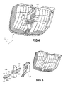
- the light guide 120 is no longer in one piece with a substantially straight tube which extends vertically, but it comprises two parts among which a substantially parallelepipedal head 84 and a body 86 formed by a tube which extends longitudinally .
- the tube has a free end 88 forming an inlet face 160 of the light and which opens into the head, which has, in a similar manner to the previous embodiment, three outlet faces.
- the main exit face 164 is arranged in the axial extension of the tube, and as previously the additional outlet faces 166 (again, only one additional outlet face is visible on the Figures 4 and 5 ) are each adjacent to the main output face 164, respectively extend in a plane not parallel to the plane in which extends the main output face. As illustrated in the figures by way of example, these additional output faces 166 may be arranged substantially perpendicular to the main exit face.
- the exit faces are provided with bearings and prismatic elements in a manner similar to that of the first embodiment.
- the particular shape of the light guide involves a different arrangement of the secondary light source and the presence of an intermediate fairing 90 between the fixing plate 122 and the light guide 120.
- the secondary light source which is not visible on Figures 4 and 5 , is carried by the mounting plate, so as to be opposite the input face of the light guide.
- the shape of the mounting plate is also modified in that it has a form of open chest forward to receive the light guide and flipped at this opening by the intermediate fairing.
- the light source is fixed on the bottom wall, opposite the opening of the plate.
- the fixing plate comprises an anchoring zone carrying ratchet means adapted to secure the plate to the support means between the collectors, and a fixing zone adapted this time to cooperate with the intermediate fairing and not directly with the light guide.
- the intermediate fairing 90 comprises a vertical bar 92 adapted to be snapped onto the mounting plate to cover the opening, the bar being cut at mid-height by a receiving portion 94 of a shape corresponding to the shape of the guide head. from light.
- the operation of the assembly is similar to that described above, the light being able to exit the light guide mainly through the exit face disposed transversely to the optical axis, and more randomly by the additional lateral exit faces for a lighting of collectors. It is observed that here the secondary light source is arranged in such a way that the light rays that it emits are directly targeted towards the main exit face.
- orientation and the type of means for anchoring the fixing plate in the support means may differ without going beyond the context of the invention.
- the module has two collectors. It will be understood that the description can be read without particular difficulty by applying it to a module in which there is a single collector, the additional optical system being on the side, or in which there are more than two collectors, at the least one additional optical system being provided between two adjacent collectors.
- the module support means carries a single collector and where a single light guide is placed on one side of the collector, it will be understood that the light guide may advantageously comprise only one additional output face, turned towards this collector.
Landscapes
- Engineering & Computer Science (AREA)
- General Engineering & Computer Science (AREA)
- Physics & Mathematics (AREA)
- Optics & Photonics (AREA)
- General Physics & Mathematics (AREA)
- Microelectronics & Electronic Packaging (AREA)
- Mechanical Engineering (AREA)
- Planar Illumination Modules (AREA)
- Non-Portable Lighting Devices Or Systems Thereof (AREA)
- Lighting Device Outwards From Vehicle And Optical Signal (AREA)
Applications Claiming Priority (1)
| Application Number | Priority Date | Filing Date | Title |
|---|---|---|---|
| FR1452340A FR3018896B1 (fr) | 2014-03-20 | 2014-03-20 | Module lumineux pour feu diurne de vehicule automobile |
Publications (2)
| Publication Number | Publication Date |
|---|---|
| EP2921771A1 true EP2921771A1 (de) | 2015-09-23 |
| EP2921771B1 EP2921771B1 (de) | 2021-07-28 |
Family
ID=50933355
Family Applications (1)
| Application Number | Title | Priority Date | Filing Date |
|---|---|---|---|
| EP15159807.5A Active EP2921771B1 (de) | 2014-03-20 | 2015-03-19 | Leuchtmodul für kraftfahrzeug |
Country Status (4)
| Country | Link |
|---|---|
| US (1) | US9766393B2 (de) |
| EP (1) | EP2921771B1 (de) |
| CN (1) | CN104930429B (de) |
| FR (1) | FR3018896B1 (de) |
Families Citing this family (6)
| Publication number | Priority date | Publication date | Assignee | Title |
|---|---|---|---|---|
| KR20170088019A (ko) * | 2016-01-22 | 2017-08-01 | 현대모비스 주식회사 | 자동차의 조명장치 |
| CN107346045B (zh) * | 2016-05-04 | 2023-09-12 | 嘉兴海拉灯具有限公司 | 一种光导部件及具有该光导部件的车灯 |
| USD887591S1 (en) * | 2017-07-21 | 2020-06-16 | GM Global Technology Operations LLC | Daytime running light |
| US10168016B1 (en) * | 2018-01-11 | 2019-01-01 | T.Y.C. Brother Industrial Co., Ltd. | Transparent vehicle lamp |
| JP7414833B2 (ja) * | 2019-08-27 | 2024-01-16 | 株式会社小糸製作所 | 車両用前照灯 |
| FR3109427A1 (fr) * | 2020-04-15 | 2021-10-22 | Psa Automobiles Sa | Glace destinée à obturer un boîtier optique pour véhicule automobile, comprenant une cloison et au moins un guide de lumière |
Citations (7)
| Publication number | Priority date | Publication date | Assignee | Title |
|---|---|---|---|---|
| FR2813654A1 (fr) * | 2000-09-04 | 2002-03-08 | Automotive Lighting Gmbh | Projecteur pour vehicule automobile associe a des feux de stationnement |
| DE20211305U1 (de) * | 2002-07-26 | 2002-10-10 | Automotive Lighting Reutlingen | Beleuchtungseinrichtung für ein Kraftfahrzeug mit mehreren Leuchteinheiten |
| DE10200359A1 (de) * | 2002-01-08 | 2003-07-17 | Automotive Lighting Reutlingen | Leuchtenanordnung, insbesondere für Kraftfahrzeuge |
| FR2934353A1 (fr) * | 2008-07-25 | 2010-01-29 | Valeo Vision Sas | Systeme optique avec fonction d'eclairage a large surface d'emission pour vehicule automobile |
| WO2012040280A2 (en) * | 2010-09-21 | 2012-03-29 | Federal-Mogul Ignition Company | Led light module |
| DE102010061210A1 (de) * | 2010-12-14 | 2012-06-14 | Hella Kgaa Hueck & Co. | Leuchte für Fahrzeuge |
| US20130201709A1 (en) * | 2012-02-07 | 2013-08-08 | Kazunori Natsume | Vehicle lamp |
Family Cites Families (11)
| Publication number | Priority date | Publication date | Assignee | Title |
|---|---|---|---|---|
| JP4049260B2 (ja) * | 2003-03-11 | 2008-02-20 | 株式会社小糸製作所 | 車両用灯具 |
| DE10311317A1 (de) * | 2003-03-14 | 2004-09-23 | Volkswagen Ag | Leuchteinrichtung für Fahrzeuge |
| ATE360256T1 (de) * | 2003-12-17 | 2007-05-15 | Schneider Electric Ind Sas | Leucht-drehtaste |
| US7275849B2 (en) * | 2005-02-25 | 2007-10-02 | Visteon Global Technologies, Inc. | LED replacement bulb |
| DE102005043992B4 (de) * | 2005-09-14 | 2010-04-08 | Automotive Lighting Reutlingen Gmbh | Signalleuchte eines Fahrzeugs |
| JP4565654B2 (ja) * | 2006-02-24 | 2010-10-20 | スタンレー電気株式会社 | 灯具 |
| JP4937649B2 (ja) * | 2006-06-28 | 2012-05-23 | 株式会社小糸製作所 | 車両用灯具 |
| JP2009158386A (ja) * | 2007-12-27 | 2009-07-16 | Koito Mfg Co Ltd | 車両用前照灯 |
| JP2012169231A (ja) * | 2011-02-17 | 2012-09-06 | Koito Mfg Co Ltd | 車両用灯具 |
| DE102011001769A1 (de) * | 2011-04-04 | 2012-10-04 | Hella Kgaa Hueck & Co. | Leuchte für ein Fahrzeug |
| CN203131654U (zh) * | 2013-01-16 | 2013-08-14 | 佳欣光电科技股份有限公司 | 导光式昼行灯 |
-
2014
- 2014-03-20 FR FR1452340A patent/FR3018896B1/fr active Active
-
2015
- 2015-03-19 US US14/662,492 patent/US9766393B2/en active Active
- 2015-03-19 EP EP15159807.5A patent/EP2921771B1/de active Active
- 2015-03-20 CN CN201510125661.1A patent/CN104930429B/zh active Active
Patent Citations (7)
| Publication number | Priority date | Publication date | Assignee | Title |
|---|---|---|---|---|
| FR2813654A1 (fr) * | 2000-09-04 | 2002-03-08 | Automotive Lighting Gmbh | Projecteur pour vehicule automobile associe a des feux de stationnement |
| DE10200359A1 (de) * | 2002-01-08 | 2003-07-17 | Automotive Lighting Reutlingen | Leuchtenanordnung, insbesondere für Kraftfahrzeuge |
| DE20211305U1 (de) * | 2002-07-26 | 2002-10-10 | Automotive Lighting Reutlingen | Beleuchtungseinrichtung für ein Kraftfahrzeug mit mehreren Leuchteinheiten |
| FR2934353A1 (fr) * | 2008-07-25 | 2010-01-29 | Valeo Vision Sas | Systeme optique avec fonction d'eclairage a large surface d'emission pour vehicule automobile |
| WO2012040280A2 (en) * | 2010-09-21 | 2012-03-29 | Federal-Mogul Ignition Company | Led light module |
| DE102010061210A1 (de) * | 2010-12-14 | 2012-06-14 | Hella Kgaa Hueck & Co. | Leuchte für Fahrzeuge |
| US20130201709A1 (en) * | 2012-02-07 | 2013-08-08 | Kazunori Natsume | Vehicle lamp |
Also Published As
| Publication number | Publication date |
|---|---|
| CN104930429A (zh) | 2015-09-23 |
| FR3018896A1 (fr) | 2015-09-25 |
| EP2921771B1 (de) | 2021-07-28 |
| US9766393B2 (en) | 2017-09-19 |
| CN104930429B (zh) | 2019-06-18 |
| US20150268406A1 (en) | 2015-09-24 |
| FR3018896B1 (fr) | 2018-05-18 |
Similar Documents
| Publication | Publication Date | Title |
|---|---|---|
| EP2921771B1 (de) | Leuchtmodul für kraftfahrzeug | |
| EP3067618B1 (de) | Leuchtvorrichtung mit optischen wellenleitern | |
| FR3002794A1 (fr) | Dispositif d'eclairage et/ou de signalisation pour vehicule automobile,comportant un guide de lumiere | |
| EP3537040B1 (de) | Leuchtmodul und leuchtvorrichtung für kraftfahrzeug, das ein solches leuchtmodul umfasst | |
| EP3803198B1 (de) | Lichtmodul für ein automobil-fahrzeug | |
| FR3103877A1 (fr) | Elément optique et module lumineux d’un véhicule automobile équipé d’un tel élément optique | |
| EP3844436B1 (de) | Kraftfahrzeuglichtmodul mit mehreren lichtleitern | |
| FR3035182A1 (fr) | Dispositif lumineux pour l'eclairage et/ou la signalisation d'un vehicule automobile | |
| FR3106651A1 (fr) | Guide de lumière plat pour module lumineux de signalisation de véhicule automobile | |
| EP2921772A1 (de) | Leuchtmodul eines kraftfahrzeugs | |
| EP3489576A1 (de) | Leuchtmodul zur beleuchtung und/oder signalisierung eines kraftfahrzeugs | |
| EP2295850A1 (de) | Vorrichtung zur Beleuchtung und/oder Signalisierung für Kraftfahrzeug | |
| EP2733413A1 (de) | Optisches Modul für KFZ-Scheinwerfer | |
| FR3088986A1 (fr) | Module lumineux multifonctions doté de deux guides de lumière de type plat | |
| FR3056698B1 (fr) | Module lumineux pour vehicule automobile | |
| EP2846081A1 (de) | Vorrichtung zur Beleuchtung und Signalisierung für Fahrzeuge | |
| EP3628914B1 (de) | Optische bifunktionseinheit zum anzeigen und beleuchten | |
| EP3867565B1 (de) | Leuchtmodul mit zwei funktionen für eine optische beleuchtungs- und/oder signaleinheit eines fahrzeugs | |
| FR3009065A1 (fr) | Dispositif optique de vehicule automobile | |
| WO2025045798A1 (fr) | Module d'éclairage pour un véhicule automobile | |
| FR3079596A1 (fr) | Dispositif optique avec guide optique et reflecteur indexes | |
| FR3146110A1 (fr) | Bloc optique de signalisation destiné à être intégré dans un projecteur de véhicule automobile | |
| WO2018007387A1 (fr) | Source lumineuse et module lumineux correspondant pour vehicule automobile | |
| FR3144249A1 (fr) | Module d’éclairage | |
| FR3129194A1 (fr) | Dispositif d’éclairage de sécurité |
Legal Events
| Date | Code | Title | Description |
|---|---|---|---|
| PUAI | Public reference made under article 153(3) epc to a published international application that has entered the european phase |
Free format text: ORIGINAL CODE: 0009012 |
|
| AK | Designated contracting states |
Kind code of ref document: A1 Designated state(s): AL AT BE BG CH CY CZ DE DK EE ES FI FR GB GR HR HU IE IS IT LI LT LU LV MC MK MT NL NO PL PT RO RS SE SI SK SM TR |
|
| AX | Request for extension of the european patent |
Extension state: BA ME |
|
| RIN1 | Information on inventor provided before grant (corrected) |
Inventor name: CABANNE, DAMIEN Inventor name: AGUILAR DEL MORAL, JOSE-ANTONIO Inventor name: CASTILLO - JIMENEZ, JOSE Inventor name: RODRIGUEZ - FUENTES, ALBERTO |
|
| 17P | Request for examination filed |
Effective date: 20160311 |
|
| RBV | Designated contracting states (corrected) |
Designated state(s): AL AT BE BG CH CY CZ DE DK EE ES FI FR GB GR HR HU IE IS IT LI LT LU LV MC MK MT NL NO PL PT RO RS SE SI SK SM TR |
|
| STAA | Information on the status of an ep patent application or granted ep patent |
Free format text: STATUS: EXAMINATION IS IN PROGRESS |
|
| 17Q | First examination report despatched |
Effective date: 20190208 |
|
| REG | Reference to a national code |
Ref country code: DE Ref legal event code: R079 Ref document number: 602015071630 Country of ref document: DE Free format text: PREVIOUS MAIN CLASS: F21S0008100000 Ipc: F21S0041148000 |
|
| GRAP | Despatch of communication of intention to grant a patent |
Free format text: ORIGINAL CODE: EPIDOSNIGR1 |
|
| STAA | Information on the status of an ep patent application or granted ep patent |
Free format text: STATUS: GRANT OF PATENT IS INTENDED |
|
| RIC1 | Information provided on ipc code assigned before grant |
Ipc: F21S 43/241 20180101ALI20210201BHEP Ipc: F21S 43/236 20180101ALI20210201BHEP Ipc: F21S 43/19 20180101ALI20210201BHEP Ipc: F21S 43/247 20180101ALI20210201BHEP Ipc: F21S 43/249 20180101ALI20210201BHEP Ipc: F21S 43/27 20180101ALI20210201BHEP Ipc: F21S 43/40 20180101ALI20210201BHEP Ipc: F21S 43/245 20180101ALI20210201BHEP Ipc: F21S 43/237 20180101ALI20210201BHEP Ipc: F21S 41/33 20180101ALI20210201BHEP Ipc: F21S 43/14 20180101ALI20210201BHEP Ipc: F21S 43/31 20180101ALI20210201BHEP Ipc: F21S 41/148 20180101AFI20210201BHEP |
|
| INTG | Intention to grant announced |
Effective date: 20210216 |
|
| RIN1 | Information on inventor provided before grant (corrected) |
Inventor name: CABANNE, DAMIEN Inventor name: CASTILLO JIMENEZ, JOSE Inventor name: RODRIGUEZ FUENTES, ALBERTO Inventor name: AGUILAR DEL MORAL, JOSE ANTONIO |
|
| GRAS | Grant fee paid |
Free format text: ORIGINAL CODE: EPIDOSNIGR3 |
|
| GRAA | (expected) grant |
Free format text: ORIGINAL CODE: 0009210 |
|
| STAA | Information on the status of an ep patent application or granted ep patent |
Free format text: STATUS: THE PATENT HAS BEEN GRANTED |
|
| AK | Designated contracting states |
Kind code of ref document: B1 Designated state(s): AL AT BE BG CH CY CZ DE DK EE ES FI FR GB GR HR HU IE IS IT LI LT LU LV MC MK MT NL NO PL PT RO RS SE SI SK SM TR |
|
| REG | Reference to a national code |
Ref country code: GB Ref legal event code: FG4D Free format text: NOT ENGLISH |
|
| REG | Reference to a national code |
Ref country code: CH Ref legal event code: EP |
|
| REG | Reference to a national code |
Ref country code: DE Ref legal event code: R096 Ref document number: 602015071630 Country of ref document: DE |
|
| REG | Reference to a national code |
Ref country code: AT Ref legal event code: REF Ref document number: 1415025 Country of ref document: AT Kind code of ref document: T Effective date: 20210815 |
|
| REG | Reference to a national code |
Ref country code: IE Ref legal event code: FG4D Free format text: LANGUAGE OF EP DOCUMENT: FRENCH |
|
| REG | Reference to a national code |
Ref country code: LT Ref legal event code: MG9D |
|
| REG | Reference to a national code |
Ref country code: NL Ref legal event code: MP Effective date: 20210728 |
|
| REG | Reference to a national code |
Ref country code: AT Ref legal event code: MK05 Ref document number: 1415025 Country of ref document: AT Kind code of ref document: T Effective date: 20210728 |
|
| PG25 | Lapsed in a contracting state [announced via postgrant information from national office to epo] |
Ref country code: FI Free format text: LAPSE BECAUSE OF FAILURE TO SUBMIT A TRANSLATION OF THE DESCRIPTION OR TO PAY THE FEE WITHIN THE PRESCRIBED TIME-LIMIT Effective date: 20210728 Ref country code: ES Free format text: LAPSE BECAUSE OF FAILURE TO SUBMIT A TRANSLATION OF THE DESCRIPTION OR TO PAY THE FEE WITHIN THE PRESCRIBED TIME-LIMIT Effective date: 20210728 Ref country code: NL Free format text: LAPSE BECAUSE OF FAILURE TO SUBMIT A TRANSLATION OF THE DESCRIPTION OR TO PAY THE FEE WITHIN THE PRESCRIBED TIME-LIMIT Effective date: 20210728 Ref country code: NO Free format text: LAPSE BECAUSE OF FAILURE TO SUBMIT A TRANSLATION OF THE DESCRIPTION OR TO PAY THE FEE WITHIN THE PRESCRIBED TIME-LIMIT Effective date: 20211028 Ref country code: PT Free format text: LAPSE BECAUSE OF FAILURE TO SUBMIT A TRANSLATION OF THE DESCRIPTION OR TO PAY THE FEE WITHIN THE PRESCRIBED TIME-LIMIT Effective date: 20211129 Ref country code: BG Free format text: LAPSE BECAUSE OF FAILURE TO SUBMIT A TRANSLATION OF THE DESCRIPTION OR TO PAY THE FEE WITHIN THE PRESCRIBED TIME-LIMIT Effective date: 20211028 Ref country code: AT Free format text: LAPSE BECAUSE OF FAILURE TO SUBMIT A TRANSLATION OF THE DESCRIPTION OR TO PAY THE FEE WITHIN THE PRESCRIBED TIME-LIMIT Effective date: 20210728 Ref country code: LT Free format text: LAPSE BECAUSE OF FAILURE TO SUBMIT A TRANSLATION OF THE DESCRIPTION OR TO PAY THE FEE WITHIN THE PRESCRIBED TIME-LIMIT Effective date: 20210728 Ref country code: RS Free format text: LAPSE BECAUSE OF FAILURE TO SUBMIT A TRANSLATION OF THE DESCRIPTION OR TO PAY THE FEE WITHIN THE PRESCRIBED TIME-LIMIT Effective date: 20210728 Ref country code: SE Free format text: LAPSE BECAUSE OF FAILURE TO SUBMIT A TRANSLATION OF THE DESCRIPTION OR TO PAY THE FEE WITHIN THE PRESCRIBED TIME-LIMIT Effective date: 20210728 Ref country code: HR Free format text: LAPSE BECAUSE OF FAILURE TO SUBMIT A TRANSLATION OF THE DESCRIPTION OR TO PAY THE FEE WITHIN THE PRESCRIBED TIME-LIMIT Effective date: 20210728 |
|
| PG25 | Lapsed in a contracting state [announced via postgrant information from national office to epo] |
Ref country code: PL Free format text: LAPSE BECAUSE OF FAILURE TO SUBMIT A TRANSLATION OF THE DESCRIPTION OR TO PAY THE FEE WITHIN THE PRESCRIBED TIME-LIMIT Effective date: 20210728 Ref country code: LV Free format text: LAPSE BECAUSE OF FAILURE TO SUBMIT A TRANSLATION OF THE DESCRIPTION OR TO PAY THE FEE WITHIN THE PRESCRIBED TIME-LIMIT Effective date: 20210728 |
|
| PG25 | Lapsed in a contracting state [announced via postgrant information from national office to epo] |
Ref country code: DK Free format text: LAPSE BECAUSE OF FAILURE TO SUBMIT A TRANSLATION OF THE DESCRIPTION OR TO PAY THE FEE WITHIN THE PRESCRIBED TIME-LIMIT Effective date: 20210728 |
|
| REG | Reference to a national code |
Ref country code: DE Ref legal event code: R097 Ref document number: 602015071630 Country of ref document: DE |
|
| PG25 | Lapsed in a contracting state [announced via postgrant information from national office to epo] |
Ref country code: SM Free format text: LAPSE BECAUSE OF FAILURE TO SUBMIT A TRANSLATION OF THE DESCRIPTION OR TO PAY THE FEE WITHIN THE PRESCRIBED TIME-LIMIT Effective date: 20210728 Ref country code: SK Free format text: LAPSE BECAUSE OF FAILURE TO SUBMIT A TRANSLATION OF THE DESCRIPTION OR TO PAY THE FEE WITHIN THE PRESCRIBED TIME-LIMIT Effective date: 20210728 Ref country code: RO Free format text: LAPSE BECAUSE OF FAILURE TO SUBMIT A TRANSLATION OF THE DESCRIPTION OR TO PAY THE FEE WITHIN THE PRESCRIBED TIME-LIMIT Effective date: 20210728 Ref country code: EE Free format text: LAPSE BECAUSE OF FAILURE TO SUBMIT A TRANSLATION OF THE DESCRIPTION OR TO PAY THE FEE WITHIN THE PRESCRIBED TIME-LIMIT Effective date: 20210728 Ref country code: CZ Free format text: LAPSE BECAUSE OF FAILURE TO SUBMIT A TRANSLATION OF THE DESCRIPTION OR TO PAY THE FEE WITHIN THE PRESCRIBED TIME-LIMIT Effective date: 20210728 Ref country code: AL Free format text: LAPSE BECAUSE OF FAILURE TO SUBMIT A TRANSLATION OF THE DESCRIPTION OR TO PAY THE FEE WITHIN THE PRESCRIBED TIME-LIMIT Effective date: 20210728 |
|
| PLBE | No opposition filed within time limit |
Free format text: ORIGINAL CODE: 0009261 |
|
| STAA | Information on the status of an ep patent application or granted ep patent |
Free format text: STATUS: NO OPPOSITION FILED WITHIN TIME LIMIT |
|
| 26N | No opposition filed |
Effective date: 20220429 |
|
| PG25 | Lapsed in a contracting state [announced via postgrant information from national office to epo] |
Ref country code: IT Free format text: LAPSE BECAUSE OF FAILURE TO SUBMIT A TRANSLATION OF THE DESCRIPTION OR TO PAY THE FEE WITHIN THE PRESCRIBED TIME-LIMIT Effective date: 20210728 |
|
| PG25 | Lapsed in a contracting state [announced via postgrant information from national office to epo] |
Ref country code: MC Free format text: LAPSE BECAUSE OF FAILURE TO SUBMIT A TRANSLATION OF THE DESCRIPTION OR TO PAY THE FEE WITHIN THE PRESCRIBED TIME-LIMIT Effective date: 20210728 |
|
| REG | Reference to a national code |
Ref country code: CH Ref legal event code: PL |
|
| GBPC | Gb: european patent ceased through non-payment of renewal fee |
Effective date: 20220319 |
|
| REG | Reference to a national code |
Ref country code: BE Ref legal event code: MM Effective date: 20220331 |
|
| PG25 | Lapsed in a contracting state [announced via postgrant information from national office to epo] |
Ref country code: LU Free format text: LAPSE BECAUSE OF NON-PAYMENT OF DUE FEES Effective date: 20220319 Ref country code: LI Free format text: LAPSE BECAUSE OF NON-PAYMENT OF DUE FEES Effective date: 20220331 Ref country code: IE Free format text: LAPSE BECAUSE OF NON-PAYMENT OF DUE FEES Effective date: 20220319 Ref country code: GB Free format text: LAPSE BECAUSE OF NON-PAYMENT OF DUE FEES Effective date: 20220319 Ref country code: CH Free format text: LAPSE BECAUSE OF NON-PAYMENT OF DUE FEES Effective date: 20220331 |
|
| PG25 | Lapsed in a contracting state [announced via postgrant information from national office to epo] |
Ref country code: BE Free format text: LAPSE BECAUSE OF NON-PAYMENT OF DUE FEES Effective date: 20220331 |
|
| P01 | Opt-out of the competence of the unified patent court (upc) registered |
Effective date: 20230629 |
|
| PG25 | Lapsed in a contracting state [announced via postgrant information from national office to epo] |
Ref country code: HU Free format text: LAPSE BECAUSE OF FAILURE TO SUBMIT A TRANSLATION OF THE DESCRIPTION OR TO PAY THE FEE WITHIN THE PRESCRIBED TIME-LIMIT; INVALID AB INITIO Effective date: 20150319 |
|
| PG25 | Lapsed in a contracting state [announced via postgrant information from national office to epo] |
Ref country code: MK Free format text: LAPSE BECAUSE OF FAILURE TO SUBMIT A TRANSLATION OF THE DESCRIPTION OR TO PAY THE FEE WITHIN THE PRESCRIBED TIME-LIMIT Effective date: 20210728 Ref country code: CY Free format text: LAPSE BECAUSE OF FAILURE TO SUBMIT A TRANSLATION OF THE DESCRIPTION OR TO PAY THE FEE WITHIN THE PRESCRIBED TIME-LIMIT Effective date: 20210728 |
|
| PG25 | Lapsed in a contracting state [announced via postgrant information from national office to epo] |
Ref country code: TR Free format text: LAPSE BECAUSE OF FAILURE TO SUBMIT A TRANSLATION OF THE DESCRIPTION OR TO PAY THE FEE WITHIN THE PRESCRIBED TIME-LIMIT Effective date: 20210728 |
|
| PG25 | Lapsed in a contracting state [announced via postgrant information from national office to epo] |
Ref country code: MT Free format text: LAPSE BECAUSE OF FAILURE TO SUBMIT A TRANSLATION OF THE DESCRIPTION OR TO PAY THE FEE WITHIN THE PRESCRIBED TIME-LIMIT Effective date: 20210728 |
|
| PG25 | Lapsed in a contracting state [announced via postgrant information from national office to epo] |
Ref country code: GR Free format text: LAPSE BECAUSE OF NON-PAYMENT OF DUE FEES Effective date: 20210728 |
|
| PG25 | Lapsed in a contracting state [announced via postgrant information from national office to epo] |
Ref country code: GR Free format text: LAPSE BECAUSE OF NON-PAYMENT OF DUE FEES Effective date: 20210728 |
|
| PGFP | Annual fee paid to national office [announced via postgrant information from national office to epo] |
Ref country code: DE Payment date: 20260313 Year of fee payment: 12 |
|
| PGFP | Annual fee paid to national office [announced via postgrant information from national office to epo] |
Ref country code: FR Payment date: 20260331 Year of fee payment: 12 |