EP2921784A1 - Porte d'appareil ménager ayant au moins un élément de revêtement élastiquement déformable entre deux vitres de porte et appareil ménager équipé d'une telle porte - Google Patents
Porte d'appareil ménager ayant au moins un élément de revêtement élastiquement déformable entre deux vitres de porte et appareil ménager équipé d'une telle porte Download PDFInfo
- Publication number
- EP2921784A1 EP2921784A1 EP15157378.9A EP15157378A EP2921784A1 EP 2921784 A1 EP2921784 A1 EP 2921784A1 EP 15157378 A EP15157378 A EP 15157378A EP 2921784 A1 EP2921784 A1 EP 2921784A1
- Authority
- EP
- European Patent Office
- Prior art keywords
- door
- panes
- cover
- edge sides
- holding element
- Prior art date
- Legal status (The legal status is an assumption and is not a legal conclusion. Google has not performed a legal analysis and makes no representation as to the accuracy of the status listed.)
- Granted
Links
Images



Classifications
-
- F—MECHANICAL ENGINEERING; LIGHTING; HEATING; WEAPONS; BLASTING
- F24—HEATING; RANGES; VENTILATING
- F24C—DOMESTIC STOVES OR RANGES ; DETAILS OF DOMESTIC STOVES OR RANGES, OF GENERAL APPLICATION
- F24C15/00—Details
- F24C15/02—Doors specially adapted for stoves or ranges
- F24C15/04—Doors specially adapted for stoves or ranges with transparent panels
Definitions
- the invention relates to a door for a household appliance with a first door glass and at least one spaced second door glass.
- the door further comprises a retaining element, which is connected to the two door panes and the door windows positionally holds each other.
- Such a door is for example from the US 4,041,930 known.
- the holding elements have Umgriffs Suitee, embrace the edge sides of the door panes.
- Umgriffs Superioren extends a spacer element which is integrally connected to these Umgriffs Suiteen, so that in a direction perpendicular to the planes of the two door panes by this spacer element, the distance between the door panes is held.
- the retaining element shown in the prior art is designed as a circumferential rigid frame.
- a corresponding embodiment is made US 5,029,571 known.
- the structure can be held on the one hand by these rigid holding elements, but on the other hand problems arise when the door panes deform and, in particular, bend due to temperature influences during operation of the cooking appliance.
- a door according to the invention for a household appliance comprises a first door pane and at least one second door pane spaced therefrom.
- the door comprises at least one retaining element, which is connected to the two door panes and holds the two door windows positionally to each other.
- An essential idea of the invention is to be seen in that at least one cover element is formed, which extends in a space between the door panes and beyond parallel to edge sides of the door panes.
- the cover element is arranged so that it at least partially covers the space between these edge sides in the direction of the edge sides and in a direction perpendicular to the Levels of the door panels is formed elastically deformable.
- This is achieved by the shape and the local attachment and the elasticity of the cover. Even if at least one of the door panes is deformed, in particular bent, when the temperature of the domestic appliance is being operated, this change in shape can likewise be performed by the elastically deformable cover element, and the space between the door panes remains closed or covered in the area of the cover element , An undesirable air flow between the cover and a door glass is prevented.
- the cover is thus also an intermediate part, which covers a gap between the mutually parallel and spaced from each other extending edge sides of the two door panes, said cover depending on the length of this cover over which it extends in the direction of these edge sides depends.
- a cover may be sufficient here, which extends only over a partial path or a partial length of these parallel edge sides.
- the specific indication of the direction in which the cover element can be elastically deformed is particularly suitable for counteracting these negative circumstances.
- this cover member is to be understood in particular as meaning that it can change its height dimensioned in the direction perpendicular to the planes of the door panes at specific locations, whereby this may occur only locally due to the local deformation of the door panes.
- the cover element is formed like a rail.
- the cover element is U-shaped in cross-section and with a leg of the U-shape on one of the second door glass facing surface side of the first door glass and with a second leg of the U-shape on a first door glass facing surface side of the second door glass is applied.
- This is a particularly advantageous embodiment, as this is on both sides of the U-shape as uniform as possible or the same mechanical contact with the door panels and in view of the deformation and the distance of the door panes, the cover can act particularly highly functional.
- the cover has at least one clip tab, with which the cover engages around an edge side of a door glass and is held on this door glass.
- this embodiment achieves a fastening possibility of the cover element on a door pane that is very easy to assemble and disassemble.
- this possibility of attachment of the cover is also very stable and permanently functional, so that the cover is positionally secure on a door glass, which then also attacks the staple tab is held.
- a plurality of individual and mutually spaced apart clip tabs are provided over the entire length of the cover, so that an improvement in the slip resistance is achieved and an undesirable tilting of the cover in the plane of this door glass is prevented. It is thus achieved at least two-point attachment of the cover on a door glass.
- At least two separate cover elements are formed, which are arranged extending on respectively opposite edge sides of the door panes in the intermediate space.
- these cover elements extend to the opposite and with the door closed vertically oriented edge sides of the door panes.
- the holding element in a ground state of the door panes which is characterized by a positional and form-specific state Characterized in that, starting from this then results in deformed when temperature of the door panes or deformed state, this door windows positionally holds such that the cover is compressed in the direction perpendicular to the planes of the door panes biased biased.
- This is also a very advantageous embodiment, since on the one hand held the positional arrangement of the cover again improved and consistent, on the other hand by biasing a quasi-sided pressures on the door panels and thus would result in a quasi pushing apart the door glasses.
- This bias is thus designed to the effect that the two legs of the U-shape are moved toward each other compared to the unloaded ground state.
- a plurality of holding elements are formed, which are arranged at least in corner regions of the door panes.
- the holding elements are preferably rigid in itself, so that there is no elastic deformation effect to compensate for a door windshield deformation.
- the holding elements are adapted in a form-specific manner to the corner regions in an essentially L-shaped manner and are designed and arranged only in these corner regions.
- a cover extends parallel to the respective edge sides of the door panes between each two holding elements, a cover, so that here in the composite between the cover elements and the holding elements a quasi all around and thus circumferentially sealed disc package results.
- the seal is to be understood in the context that no unwanted air flows due to leakage due to the deformation of the door panes between such a door glass and a cover occurs. It is therefore not a gas-tight seal to understand and required, but only to understand an embodiment including, in the unwanted leakage air currents, which could have an undesirable positive or negative temperature influence on one or more door panels is prevented.
- two cover elements and two retaining elements are provided in an embodiment of quadrangular door windows with thus four edge sides.
- a holding element is U-shaped and extends over the entire length of one edge side of two parallel edge sides of the door panes and still encompasses the corner areas adjoining these edge sides.
- the holding elements are thus designed as a kind of U-shaped bracket.
- This is then preferably also at the opposite and extending parallel to further edge sides of the two door panes by a further holding element, which is designed and shaped accordingly provided.
- Cover elements then extend as connecting parts between the two retaining elements, so that even in such an embodiment, in turn, in particular, a completely circumferential structure is formed from the retaining elements and the cover elements. Again, then a completely sealed design in the sense of the above explanation is achieved.
- the holding element is designed in a plane parallel to a door glass or in a plane of the door glass U-shaped.
- the cover is formed in a plane perpendicular to the planes of the door panes and thus in a plane perpendicular to a longitudinal axis of such a cover U-shaped.
- a holding element is strip-like and surrounds parallel edge sides of the door panes. This encompassing is then again in a plane perpendicular to the two door windows to understand so that this holding element is quasi a certain edge protection or edge protection for the door panels.
- the relative position of the door panes is favored by this configuration, the other.
- a first retaining element surrounds at least the upper horizontal edge sides of the door panes and a second retaining element engages around at least the lower horizontal edge sides of the door panes.
- the holding elements are thus formed in this embodiment as upper horizontally extending parts and lower horizontally extending parts.
- a horizontal edge side of a door closer to a cooking chamber of a household appliance door from the at least two door windows over at least 80%, in particular at least 90%, the length of the edge side is encompassed by the holding element. Since the retaining element in the direction of its longitudinal axis by the shape is very stable and thus very well withstand bending against the longitudinal axis, a very rigid part is provided by this configuration, which also a deformation of a door glass and thus bending the door glass from his Counteracts level out.
- the holding element holds edge sides of the door panes to be held with play.
- this design involving play is to be understood as meaning that only relatively small movement tolerances are permitted in order to be able to give way to undesirable stresses in the case of temperature influences on the door panes if an immediately rigid reception and spreading of the door panes occurs in the grip areas of the holding elements. As a result, cracking in the door panes can be avoided if necessary.
- just by this defined and intended small game-affixed attachment and the functionality of the cover member is taken better account, so that here then the corresponding deformation elasticity of the cover can be improved to advantage.
- a holding element has edge sides of the door panes encompassing gripping areas and at least one spacer bar which extends from a gripping area encompassing the edge of a door pane extends freely cantilevering in the direction of the other gripping area and rests in the mounted state on the door pane surrounded by the other gripping area.
- this spacer is not vertical and thus perpendicular to the door panels standing element, which would then be rigid in itself. Rather, this spacer bracket is preferably an inclined and / or angled bracket, which then rests with a curved end portion on the inside of the opposite door glass.
- the holding element and the cover are non-destructively releasably connected, in particular latched.
- these separate parts it is also possible for these separate parts to be held in a certain positional fixation with respect to one another and, especially in the case of a design in which a completely circumferential concept is realized in the composite of these holding elements and cover elements, the mechanical support of the entire components with respect to one another can also be improved.
- the above-mentioned sealing concept is improved by such a configuration.
- the total number of cover elements and the total number of holding elements form a peripheral frame.
- cover and the holding element are non-destructively formed nondestructive.
- the invention relates to a household appliance for preparing food, which has a door according to the invention or an advantageous embodiment, and which is designed and arranged for closing a cooking chamber of the household appliance.
- this disc package with the at least two door panes and the at least provided holding elements and at least provided cover elements independently of the door and the household appliance as such is preassembled and can be provided with respect to already pre-assembled assembly for further assembly.
- a cover made of plastic or metal, for example, as a thin sheet steel or spring plate is formed.
- a covering element which extends adjacent to an edge side or parallel to the edge sides of door panes is preferably formed in one piece.
- the Umgriffs Surreye a holding element by additional components made of metal or plastic, such as silicone, are formed and mounted between the support member and the respective door glass, in particular to avoid rattling. It can also be provided that more than two separate door panes are held positionally relative to each other by such cover elements and holding elements and that the respective spaces formed by the spacing of the parallel plate-like door panes are correspondingly covered.
- the aspects achieved by the holding elements and the cover elements and thus also their functional interaction have a positive influence on the temperature development of the individual door panes, on the energy consumption of the household appliance and thus also on the cooking result.
- the ventilation of the door can be defined by the respective individual spaces between the door panes.
- the cover also other components, such as side panels of the door are protected from the high temperature from the oven and can be made of less expensive materials.
- such a solution creates the freedom to replace more costly sealing materials with more common and less expensive materials, such as spring steel sheet or thin steel sheets.
- Fig. 1 is a household appliance 1 for preparing food, such as an oven, shown.
- the household appliance 1 comprises a housing 2, which surrounds a muffle 3.
- the muffle 3 limits with its walls a cooking chamber 4, in which food can be introduced for preparing.
- the muffle 3 has on the front side a charging opening, which can be closed by a door 5.
- the door 5 is in the exemplary embodiment a flap door which is pivotable about a horizontal axis A.
- the household appliance 1 further comprises in position and embodiment, for example only shown an operating device 6 with a display unit 7 and controls 8 and 9.
- the household appliance 1 may also have a hob with cooking zones.
- the household appliance 1 can also be equipped with a pyrolysis function.
- the door 5 is shown in a further schematic representation with sub-components. It has a windscreen or an outer disk 10, which faces the viewer 5 in the closed state of the door 5 and faces away from the cooking chamber 4.
- the door 5 comprises an inner pane 11 which, in the closed state of the door 5, is the pane closest to the cooking space 4.
- the door 5 comprises at least one, in the exemplary embodiment two, intermediate disks 12 and 13 which are arranged between the front screen 10 and the inner disk 11.
- the discs 10 to 13 are plate-shaped and oriented parallel to each other, each with a gap 14, 15 and 16 between formed adjacent discs. It is provided that the door 5 is ventilated specifically, on the one hand to keep the windshield 10 as cool as possible, on the other hand, the inner disk 11 as little as possible to cool. For this purpose, very specific air ducts through the door 5 are specified.
- a door profile 17 is provided, which is arranged on the windshield 10, and which serves as a carrier for the further discs 11 to 13.
- a corresponding door profile is also formed on the left opposite side.
- Fig. 2 shown schematically exaggerated, in which context the inner pane and an intermediate disc correspondingly bulge and thus the completely flat configuration in itself and the completely parallel orientation of the discs is no longer given to each other.
- FIG. 3 in a schematic partial sectional view of an embodiment of components of the door 5 shown.
- at least one cover element 18 is arranged at least between two panes, for example the inner pane 11 and the then directly following first intermediate pane 12.
- the cover member 18 extends into the gap 14 between the two adjacent discs 11 and 12.
- the cover 18 is also formed in a straight line and strip-like and extends in this respect perpendicular to the plane of the figure in the y-direction.
- the cover member 18 extends in the context thus also in a straight line in the direction of the mutually parallel edge sides 11a and 12a of the square door panels 11 and 12.
- the space 14 is through this Covering element 18 completely covered in the z-direction between these edge sides 11a and 12a and covered in the direction of the longitudinal extent, which is dimensioned in the y-direction, of the cover element 18 at least over the length of the cover element 18.
- the cover member 18 is at least as long as the shorter in the y direction edge or the shorter of the two edge sides 11a and 12a.
- the cover member 18 in the z-direction and thus in a direction perpendicular to the planes of the door panes 11 and 12, which span in the x-y plane, is elastically deformable or springs formed.
- the cover member 18 is preferably configured in one piece and molded from plastic or a metal. It is in the cross section perpendicular to the planes in which the door panels 11 and 12 span, and thus formed in an x-z plane with a U-shaped part 19. It is provided that a first leg 19a on one of the first door glass designated inner disk 11 facing surface side 12b of the intermediate disc 12 abuts and another leg 19b of the U-shape on an intermediate disc 12 facing surface side 11b of the inner disc 11 abuts. This U-shape can be compressed in the z-direction, so that the height measured in the z-direction is variable.
- the cover element 18 comprises at least one, preferably a plurality of clip tabs 20, 21 and 22 (FIG. Fig. 4 ).
- the clip tabs 20 to 22 are also U-shaped in the cross section shown and surround the edge 12a of the washer 12, so that the cover 18 is also held on this washer 12.
- Fig. 4 an embodiment of a cover 18 is shown in a perspective view. It is there, as well as in Fig. 3 , that the leg 19b facing away from the staple flap 20 is longer in the x-direction than the leg 19a.
- the cover member 18 is according to the embodiment in Fig. 4 also shaft-like or channel-shaped and thus covers over its entire length the gap 14 in the z-direction between the door panes 11 and 12 from.
- Fig. 5 is shown in a further perspective view of an assembled state of two separate cover members 18 and the door panes 11 and 12.
- Fig. 3 is the sectional view along the section line III-III in Fig. 5 shown.
- the two identically constructed cover elements 18 are arranged on respectively opposite, parallel edge sides of the door windows 11 and 12.
- the left-side cover element 18 is arranged parallel to the edge sides 11a and 12a, which represent vertical edge sides in the closed state of the door 5.
- the right-side cover member 18 is arranged to extend parallel to the two edge sides 11c and 12c.
- Fig. 6 is an embodiment of the door 5 is shown in a further perspective view.
- an arrangement of holding elements 23 and 24 is shown.
- the holding elements 23 and 24 extend on the one hand over the entire length of the horizontally extending edge sides 11d and 12d and the horizontal edge sides 11e and 12e of the door panes 11 and 12. They are therefore arranged at the top and bottom of the door panels 11 and 12 and extending horizontally.
- the holding elements 23 and 24, which are rigid in itself and in contrast to the cover 18 is not elastically deformable, in the xy plane are also U-shaped.
- the already mentioned and explained U-shape of the cover 18 but realized in the xz plane.
- the holding elements 23 and 24 are also arranged around the corner regions 12f, 12g, 12h and 12i of the intermediate plate 12.
- the two cover members 18 which extend only in a straight line in the y-direction, and the two holding elements 23 and 24 a circumferentially encircling the four edge sides of the door panes, sealing frame.
- the seal does not refer here to a gas tightness, but to a tightness with respect to unwanted leakage flows of the ventilation flows generated in the door 5.
- the holding elements 23 and 24 provided as separate components on the one hand and the two cover elements 18 on the other hand are non-destructively releasably connected, in particular latched.
- Fig. 7 is in a sectional view along the section line VII-VII in Fig. 6 an embodiment of a holding element shown.
- the holding element 23 is designed as multiply angled and thus stepped component, whereby it has a very high rigidity. It comprises wraparound areas 23a and 23b.
- the Umgriffs Schemee 23a and 23b in turn surround edge sides of the discs 11 and 12.
- the holding member 23 comprises a spacer bracket 23c. This extends from the Umgriffs Scheme 23b toward the other Umgriffs Scheme 23 cantilevered, and he lies in the assembled state, as in Fig. 7 is shown, at the encompassed by the other Umgriffs Scheme 23 a door glass.
- the spacer bow 23c is bent several times, so that it also has a certain elasticity and thereby also in the z-direction is deformable.
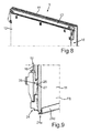
- Fig. 8 is in a further perspective view of the door 5, as shown in Fig. 6 is shown in the upper area.
- the holding element 23 and a lateral cover element 18 can be seen.
- Fig. 9 is an enlarged view of the area I in Fig. 6 shown.
- the holding element 24 is locked with a cover 18 at a Verraststelle 25.
- a latching nose 26 snaps onto the cover element 18 into a latching receptacle 27 in the holding element 24.
- the holding element 24 is designed in its shape such that an inner side 11j of the inner pane 11 facing the cooking chamber is encompassed by the gripping area 24a such that preferably a web 24d extends over the entire length of the encompassed edge side, so that Here, too, a certain support and dimensional stability for the inner pane 11 is given.
- the Umgriffs Kunststoffe 23 a and 23 b are dimensioned so that the discs 11 and 12 are received therein with a defined play. As a result, a certain movement deformation is allowed.
- FIG. 10 an embodiment is shown in which both an upper support member 23 and a lower support member 24 as shown in FIG Fig. 9 are formed and have corresponding flanges or webs 23d and 24d. These are formed on the previously described Umgriffs Suiteen 23a and 24a.
- a further embodiment of the door 5 is shown in a perspective view.
- the holding element 23 and 24 are not designed as U-shaped moldings, but designed only as L-shaped angled parts. They are arranged in the context only in the corners 12f to 12i.
- each separate cover 18 extend between these four holding elements 23 and 24, so that four cover elements 18 and four holding elements 23 and 24 are provided in this embodiment. Again, the respective separate components are locked together, so that here is a circumferentially closed frame formed by these four cover members 18 and these four holding elements 23 and 24 respectively.
Landscapes
- Engineering & Computer Science (AREA)
- Chemical & Material Sciences (AREA)
- Combustion & Propulsion (AREA)
- Mechanical Engineering (AREA)
- General Engineering & Computer Science (AREA)
- Securing Of Glass Panes Or The Like (AREA)
- Electric Ovens (AREA)
Priority Applications (1)
| Application Number | Priority Date | Filing Date | Title |
|---|---|---|---|
| PL15157378T PL2921784T3 (pl) | 2014-03-19 | 2015-03-03 | Drzwi do urządzenia gospodarstwa domowego z co najmniej jednym elastycznie odkształcanym elementem osłonowym między dwiema szybami drzwiowymi i urządzenie gospodarstwa domowego z tego rodzaju drzwiami |
Applications Claiming Priority (2)
| Application Number | Priority Date | Filing Date | Title |
|---|---|---|---|
| DE102014205114 | 2014-03-19 | ||
| DE102014216566.0A DE102014216566B4 (de) | 2014-03-19 | 2014-08-21 | Tür für ein Haushaltsgerät mit zumindest einem elastisch verformbaren Abdeckelement zwischen zwei Türscheiben sowie Haushaltsgerät mit einer derartigen Tür |
Publications (2)
| Publication Number | Publication Date |
|---|---|
| EP2921784A1 true EP2921784A1 (fr) | 2015-09-23 |
| EP2921784B1 EP2921784B1 (fr) | 2020-12-02 |
Family
ID=52595222
Family Applications (1)
| Application Number | Title | Priority Date | Filing Date |
|---|---|---|---|
| EP15157378.9A Active EP2921784B1 (fr) | 2014-03-19 | 2015-03-03 | Porte d'appareil ménager ayant au moins un élément de revêtement élastiquement déformable entre deux vitres de porte et appareil ménager équipé d'une telle porte |
Country Status (3)
| Country | Link |
|---|---|
| EP (1) | EP2921784B1 (fr) |
| DE (1) | DE102014216566B4 (fr) |
| PL (1) | PL2921784T3 (fr) |
Cited By (3)
| Publication number | Priority date | Publication date | Assignee | Title |
|---|---|---|---|---|
| DE102017223075A1 (de) * | 2017-12-18 | 2019-06-19 | BSH Hausgeräte GmbH | Haushaltsgargerät |
| WO2022017798A1 (fr) * | 2020-07-22 | 2022-01-27 | BSH Hausgeräte GmbH | Porte et dispositif domestique de cuisson |
| US12422145B2 (en) | 2021-06-17 | 2025-09-23 | Midea Group Co., Ltd. | Appliance corner cap |
Citations (6)
| Publication number | Priority date | Publication date | Assignee | Title |
|---|---|---|---|---|
| US4041930A (en) | 1975-11-28 | 1977-08-16 | Mills Products, Inc. | Window unit for oven doors |
| US5029571A (en) | 1990-08-23 | 1991-07-09 | Mills Products, Inc. | Oven door window unit |
| US5799647A (en) * | 1997-09-12 | 1998-09-01 | Mills Products, Inc. | Oven door window unit |
| EP1308676A2 (fr) * | 2001-10-31 | 2003-05-07 | BSH Bosch und Siemens Hausgeräte GmbH | Porte d'un four de cuisson |
| EP1647775A2 (fr) * | 2004-10-13 | 2006-04-19 | Lg Electronics Inc. | Four avec dispositif de support de vitres |
| EP2330357A2 (fr) * | 2009-12-03 | 2011-06-08 | BSH Bosch und Siemens Hausgeräte GmbH | Elément de retenue pour un panneau vitré, porte pour un appareil ménager dotée d'un tel élément de retenue et procédé de montage d'une porte pour un appareil ménager |
Family Cites Families (4)
| Publication number | Priority date | Publication date | Assignee | Title |
|---|---|---|---|---|
| DE2205279B2 (de) | 1972-02-04 | 1978-11-09 | Bosch-Siemens Hausgeraete Gmbh, 7000 Stuttgart | Backofen-Turf enster |
| ES2393150B1 (es) * | 2010-03-26 | 2013-10-23 | Bsh Electrodomésticos España, S.A. | Unidad de puerta de aparato de cocción. |
| DE102011088082B4 (de) | 2011-12-09 | 2022-03-31 | BSH Hausgeräte GmbH | Tür für ein Haushaltsgerät sowie Haushaltsgerät mit einer Tür |
| DE102011088073B4 (de) | 2011-12-09 | 2024-08-01 | BSH Hausgeräte GmbH | Tür für ein Haushaltsgerät sowie Gargerät mit einer derartigen Tür |
-
2014
- 2014-08-21 DE DE102014216566.0A patent/DE102014216566B4/de active Active
-
2015
- 2015-03-03 EP EP15157378.9A patent/EP2921784B1/fr active Active
- 2015-03-03 PL PL15157378T patent/PL2921784T3/pl unknown
Patent Citations (6)
| Publication number | Priority date | Publication date | Assignee | Title |
|---|---|---|---|---|
| US4041930A (en) | 1975-11-28 | 1977-08-16 | Mills Products, Inc. | Window unit for oven doors |
| US5029571A (en) | 1990-08-23 | 1991-07-09 | Mills Products, Inc. | Oven door window unit |
| US5799647A (en) * | 1997-09-12 | 1998-09-01 | Mills Products, Inc. | Oven door window unit |
| EP1308676A2 (fr) * | 2001-10-31 | 2003-05-07 | BSH Bosch und Siemens Hausgeräte GmbH | Porte d'un four de cuisson |
| EP1647775A2 (fr) * | 2004-10-13 | 2006-04-19 | Lg Electronics Inc. | Four avec dispositif de support de vitres |
| EP2330357A2 (fr) * | 2009-12-03 | 2011-06-08 | BSH Bosch und Siemens Hausgeräte GmbH | Elément de retenue pour un panneau vitré, porte pour un appareil ménager dotée d'un tel élément de retenue et procédé de montage d'une porte pour un appareil ménager |
Cited By (4)
| Publication number | Priority date | Publication date | Assignee | Title |
|---|---|---|---|---|
| DE102017223075A1 (de) * | 2017-12-18 | 2019-06-19 | BSH Hausgeräte GmbH | Haushaltsgargerät |
| WO2022017798A1 (fr) * | 2020-07-22 | 2022-01-27 | BSH Hausgeräte GmbH | Porte et dispositif domestique de cuisson |
| US12601503B2 (en) | 2020-07-22 | 2026-04-14 | BSH Hausgeräte GmbH | Door and domestic cooking device |
| US12422145B2 (en) | 2021-06-17 | 2025-09-23 | Midea Group Co., Ltd. | Appliance corner cap |
Also Published As
| Publication number | Publication date |
|---|---|
| PL2921784T3 (pl) | 2021-06-14 |
| DE102014216566B4 (de) | 2025-01-09 |
| DE102014216566A1 (de) | 2015-09-24 |
| EP2921784B1 (fr) | 2020-12-02 |
Similar Documents
| Publication | Publication Date | Title |
|---|---|---|
| EP0699871B1 (fr) | Porte d'un appareil de cuisson | |
| EP2325565A2 (fr) | Elément de fixation | |
| EP2128529A2 (fr) | Moufle de four | |
| DE102004002466A1 (de) | Haushaltsgerätetür mit einer Vorrichtung mit einer Scharniereinheit | |
| EP2921784B1 (fr) | Porte d'appareil ménager ayant au moins un élément de revêtement élastiquement déformable entre deux vitres de porte et appareil ménager équipé d'une telle porte | |
| EP4185814B1 (fr) | Porte et dispositif de cuisson domestique | |
| DE102011088082B4 (de) | Tür für ein Haushaltsgerät sowie Haushaltsgerät mit einer Tür | |
| EP1726884B1 (fr) | Porte d'un four cuisinière | |
| DE102010046315B4 (de) | Klimaanlage für Kraftfahrzeuge | |
| EP2369240B1 (fr) | Porte d'appareil de cuisson | |
| EP2662635B1 (fr) | Appareil ménager | |
| DE102008013004B4 (de) | Anordnung mit einem Kochfeld und einer Arbeitsplatte | |
| DE10314507A1 (de) | Blechteil, insbesondere Gargerätemuffel | |
| EP2196735A2 (fr) | Moufle pour un appareil de cuisson | |
| EP2145135B1 (fr) | Parois latérales d'un logement pour hotte aspirante, logement pour hotte aspirante et hotte aspirante correspondante | |
| DE10259744B4 (de) | Montagerahmen für ein Kochfeld sowie Verfahren zur Herstellung eines Montagerahmens | |
| EP1918645A1 (fr) | Porte d'un four de cuisson | |
| DE102014206280B4 (de) | Tür für ein Haushaltsgerät mit einer zweidimensional wirkenden Halte- und Positioniervorrichtung für eine Türscheibe sowie Haushaltsgerät mit einer Tür und Verfahren zur Montage einer Tür | |
| EP1982116A2 (fr) | Appareil de cuisson, en particulier appareil de cuisson pour installation en hauteur, et procédé de fabrication dudit appareil | |
| DE10144064A1 (de) | Gargerätetür | |
| DE29724430U1 (de) | Tür zum Verschließen der Ofenmuffel eines Back- und Bratofens | |
| DE102012203380A1 (de) | Kochfeld mit einem Montagerahmen in einem Zierrahmen sowie Verfahren zum Herstellen eines Kochfelds | |
| DE102014217642B4 (de) | Gargerät mit einer Flanschgesamtfläche | |
| DE102008017776A1 (de) | Vorrichtung mit einem Kochfeldgehäuse | |
| WO2024132087A1 (fr) | Élément d'étanchéité sous haute température |
Legal Events
| Date | Code | Title | Description |
|---|---|---|---|
| PUAI | Public reference made under article 153(3) epc to a published international application that has entered the european phase |
Free format text: ORIGINAL CODE: 0009012 |
|
| AK | Designated contracting states |
Kind code of ref document: A1 Designated state(s): AL AT BE BG CH CY CZ DE DK EE ES FI FR GB GR HR HU IE IS IT LI LT LU LV MC MK MT NL NO PL PT RO RS SE SI SK SM TR |
|
| AX | Request for extension of the european patent |
Extension state: BA ME |
|
| 17P | Request for examination filed |
Effective date: 20160323 |
|
| RBV | Designated contracting states (corrected) |
Designated state(s): AL AT BE BG CH CY CZ DE DK EE ES FI FR GB GR HR HU IE IS IT LI LT LU LV MC MK MT NL NO PL PT RO RS SE SI SK SM TR |
|
| STAA | Information on the status of an ep patent application or granted ep patent |
Free format text: STATUS: EXAMINATION IS IN PROGRESS |
|
| 17Q | First examination report despatched |
Effective date: 20170808 |
|
| GRAP | Despatch of communication of intention to grant a patent |
Free format text: ORIGINAL CODE: EPIDOSNIGR1 |
|
| STAA | Information on the status of an ep patent application or granted ep patent |
Free format text: STATUS: GRANT OF PATENT IS INTENDED |
|
| INTG | Intention to grant announced |
Effective date: 20200721 |
|
| GRAS | Grant fee paid |
Free format text: ORIGINAL CODE: EPIDOSNIGR3 |
|
| GRAA | (expected) grant |
Free format text: ORIGINAL CODE: 0009210 |
|
| STAA | Information on the status of an ep patent application or granted ep patent |
Free format text: STATUS: THE PATENT HAS BEEN GRANTED |
|
| AK | Designated contracting states |
Kind code of ref document: B1 Designated state(s): AL AT BE BG CH CY CZ DE DK EE ES FI FR GB GR HR HU IE IS IT LI LT LU LV MC MK MT NL NO PL PT RO RS SE SI SK SM TR |
|
| REG | Reference to a national code |
Ref country code: GB Ref legal event code: FG4D Free format text: NOT ENGLISH |
|
| REG | Reference to a national code |
Ref country code: AT Ref legal event code: REF Ref document number: 1341340 Country of ref document: AT Kind code of ref document: T Effective date: 20201215 Ref country code: CH Ref legal event code: EP |
|
| REG | Reference to a national code |
Ref country code: IE Ref legal event code: FG4D Free format text: LANGUAGE OF EP DOCUMENT: GERMAN |
|
| REG | Reference to a national code |
Ref country code: DE Ref legal event code: R096 Ref document number: 502015013922 Country of ref document: DE |
|
| PG25 | Lapsed in a contracting state [announced via postgrant information from national office to epo] |
Ref country code: FI Free format text: LAPSE BECAUSE OF FAILURE TO SUBMIT A TRANSLATION OF THE DESCRIPTION OR TO PAY THE FEE WITHIN THE PRESCRIBED TIME-LIMIT Effective date: 20201202 Ref country code: RS Free format text: LAPSE BECAUSE OF FAILURE TO SUBMIT A TRANSLATION OF THE DESCRIPTION OR TO PAY THE FEE WITHIN THE PRESCRIBED TIME-LIMIT Effective date: 20201202 Ref country code: NO Free format text: LAPSE BECAUSE OF FAILURE TO SUBMIT A TRANSLATION OF THE DESCRIPTION OR TO PAY THE FEE WITHIN THE PRESCRIBED TIME-LIMIT Effective date: 20210302 Ref country code: GR Free format text: LAPSE BECAUSE OF FAILURE TO SUBMIT A TRANSLATION OF THE DESCRIPTION OR TO PAY THE FEE WITHIN THE PRESCRIBED TIME-LIMIT Effective date: 20210303 |
|
| REG | Reference to a national code |
Ref country code: NL Ref legal event code: MP Effective date: 20201202 |
|
| PG25 | Lapsed in a contracting state [announced via postgrant information from national office to epo] |
Ref country code: SE Free format text: LAPSE BECAUSE OF FAILURE TO SUBMIT A TRANSLATION OF THE DESCRIPTION OR TO PAY THE FEE WITHIN THE PRESCRIBED TIME-LIMIT Effective date: 20201202 Ref country code: LV Free format text: LAPSE BECAUSE OF FAILURE TO SUBMIT A TRANSLATION OF THE DESCRIPTION OR TO PAY THE FEE WITHIN THE PRESCRIBED TIME-LIMIT Effective date: 20201202 Ref country code: BG Free format text: LAPSE BECAUSE OF FAILURE TO SUBMIT A TRANSLATION OF THE DESCRIPTION OR TO PAY THE FEE WITHIN THE PRESCRIBED TIME-LIMIT Effective date: 20210302 |
|
| PG25 | Lapsed in a contracting state [announced via postgrant information from national office to epo] |
Ref country code: NL Free format text: LAPSE BECAUSE OF FAILURE TO SUBMIT A TRANSLATION OF THE DESCRIPTION OR TO PAY THE FEE WITHIN THE PRESCRIBED TIME-LIMIT Effective date: 20201202 Ref country code: HR Free format text: LAPSE BECAUSE OF FAILURE TO SUBMIT A TRANSLATION OF THE DESCRIPTION OR TO PAY THE FEE WITHIN THE PRESCRIBED TIME-LIMIT Effective date: 20201202 |
|
| REG | Reference to a national code |
Ref country code: LT Ref legal event code: MG9D |
|
| PG25 | Lapsed in a contracting state [announced via postgrant information from national office to epo] |
Ref country code: LT Free format text: LAPSE BECAUSE OF FAILURE TO SUBMIT A TRANSLATION OF THE DESCRIPTION OR TO PAY THE FEE WITHIN THE PRESCRIBED TIME-LIMIT Effective date: 20201202 Ref country code: RO Free format text: LAPSE BECAUSE OF FAILURE TO SUBMIT A TRANSLATION OF THE DESCRIPTION OR TO PAY THE FEE WITHIN THE PRESCRIBED TIME-LIMIT Effective date: 20201202 Ref country code: SK Free format text: LAPSE BECAUSE OF FAILURE TO SUBMIT A TRANSLATION OF THE DESCRIPTION OR TO PAY THE FEE WITHIN THE PRESCRIBED TIME-LIMIT Effective date: 20201202 Ref country code: PT Free format text: LAPSE BECAUSE OF FAILURE TO SUBMIT A TRANSLATION OF THE DESCRIPTION OR TO PAY THE FEE WITHIN THE PRESCRIBED TIME-LIMIT Effective date: 20210405 Ref country code: CZ Free format text: LAPSE BECAUSE OF FAILURE TO SUBMIT A TRANSLATION OF THE DESCRIPTION OR TO PAY THE FEE WITHIN THE PRESCRIBED TIME-LIMIT Effective date: 20201202 Ref country code: EE Free format text: LAPSE BECAUSE OF FAILURE TO SUBMIT A TRANSLATION OF THE DESCRIPTION OR TO PAY THE FEE WITHIN THE PRESCRIBED TIME-LIMIT Effective date: 20201202 Ref country code: SM Free format text: LAPSE BECAUSE OF FAILURE TO SUBMIT A TRANSLATION OF THE DESCRIPTION OR TO PAY THE FEE WITHIN THE PRESCRIBED TIME-LIMIT Effective date: 20201202 |
|
| REG | Reference to a national code |
Ref country code: DE Ref legal event code: R097 Ref document number: 502015013922 Country of ref document: DE |
|
| PG25 | Lapsed in a contracting state [announced via postgrant information from national office to epo] |
Ref country code: IS Free format text: LAPSE BECAUSE OF FAILURE TO SUBMIT A TRANSLATION OF THE DESCRIPTION OR TO PAY THE FEE WITHIN THE PRESCRIBED TIME-LIMIT Effective date: 20210402 |
|
| PLBE | No opposition filed within time limit |
Free format text: ORIGINAL CODE: 0009261 |
|
| STAA | Information on the status of an ep patent application or granted ep patent |
Free format text: STATUS: NO OPPOSITION FILED WITHIN TIME LIMIT |
|
| PG25 | Lapsed in a contracting state [announced via postgrant information from national office to epo] |
Ref country code: IT Free format text: LAPSE BECAUSE OF FAILURE TO SUBMIT A TRANSLATION OF THE DESCRIPTION OR TO PAY THE FEE WITHIN THE PRESCRIBED TIME-LIMIT Effective date: 20201202 Ref country code: AL Free format text: LAPSE BECAUSE OF FAILURE TO SUBMIT A TRANSLATION OF THE DESCRIPTION OR TO PAY THE FEE WITHIN THE PRESCRIBED TIME-LIMIT Effective date: 20201202 Ref country code: MC Free format text: LAPSE BECAUSE OF FAILURE TO SUBMIT A TRANSLATION OF THE DESCRIPTION OR TO PAY THE FEE WITHIN THE PRESCRIBED TIME-LIMIT Effective date: 20201202 |
|
| REG | Reference to a national code |
Ref country code: CH Ref legal event code: PL |
|
| 26N | No opposition filed |
Effective date: 20210903 |
|
| PG25 | Lapsed in a contracting state [announced via postgrant information from national office to epo] |
Ref country code: DK Free format text: LAPSE BECAUSE OF FAILURE TO SUBMIT A TRANSLATION OF THE DESCRIPTION OR TO PAY THE FEE WITHIN THE PRESCRIBED TIME-LIMIT Effective date: 20201202 Ref country code: ES Free format text: LAPSE BECAUSE OF FAILURE TO SUBMIT A TRANSLATION OF THE DESCRIPTION OR TO PAY THE FEE WITHIN THE PRESCRIBED TIME-LIMIT Effective date: 20201202 Ref country code: SI Free format text: LAPSE BECAUSE OF FAILURE TO SUBMIT A TRANSLATION OF THE DESCRIPTION OR TO PAY THE FEE WITHIN THE PRESCRIBED TIME-LIMIT Effective date: 20201202 |
|
| REG | Reference to a national code |
Ref country code: BE Ref legal event code: MM Effective date: 20210331 |
|
| PG25 | Lapsed in a contracting state [announced via postgrant information from national office to epo] |
Ref country code: IE Free format text: LAPSE BECAUSE OF NON-PAYMENT OF DUE FEES Effective date: 20210303 Ref country code: CH Free format text: LAPSE BECAUSE OF NON-PAYMENT OF DUE FEES Effective date: 20210331 Ref country code: LU Free format text: LAPSE BECAUSE OF NON-PAYMENT OF DUE FEES Effective date: 20210303 Ref country code: LI Free format text: LAPSE BECAUSE OF NON-PAYMENT OF DUE FEES Effective date: 20210331 |
|
| REG | Reference to a national code |
Ref country code: AT Ref legal event code: MM01 Ref document number: 1341340 Country of ref document: AT Kind code of ref document: T Effective date: 20210303 |
|
| PG25 | Lapsed in a contracting state [announced via postgrant information from national office to epo] |
Ref country code: IS Free format text: LAPSE BECAUSE OF FAILURE TO SUBMIT A TRANSLATION OF THE DESCRIPTION OR TO PAY THE FEE WITHIN THE PRESCRIBED TIME-LIMIT Effective date: 20210402 |
|
| PG25 | Lapsed in a contracting state [announced via postgrant information from national office to epo] |
Ref country code: BE Free format text: LAPSE BECAUSE OF NON-PAYMENT OF DUE FEES Effective date: 20210331 |
|
| PG25 | Lapsed in a contracting state [announced via postgrant information from national office to epo] |
Ref country code: AT Free format text: LAPSE BECAUSE OF NON-PAYMENT OF DUE FEES Effective date: 20210303 |
|
| PG25 | Lapsed in a contracting state [announced via postgrant information from national office to epo] |
Ref country code: HU Free format text: LAPSE BECAUSE OF FAILURE TO SUBMIT A TRANSLATION OF THE DESCRIPTION OR TO PAY THE FEE WITHIN THE PRESCRIBED TIME-LIMIT; INVALID AB INITIO Effective date: 20150303 |
|
| PG25 | Lapsed in a contracting state [announced via postgrant information from national office to epo] |
Ref country code: CY Free format text: LAPSE BECAUSE OF FAILURE TO SUBMIT A TRANSLATION OF THE DESCRIPTION OR TO PAY THE FEE WITHIN THE PRESCRIBED TIME-LIMIT Effective date: 20201202 |
|
| PG25 | Lapsed in a contracting state [announced via postgrant information from national office to epo] |
Ref country code: MK Free format text: LAPSE BECAUSE OF FAILURE TO SUBMIT A TRANSLATION OF THE DESCRIPTION OR TO PAY THE FEE WITHIN THE PRESCRIBED TIME-LIMIT Effective date: 20201202 |
|
| PG25 | Lapsed in a contracting state [announced via postgrant information from national office to epo] |
Ref country code: MT Free format text: LAPSE BECAUSE OF FAILURE TO SUBMIT A TRANSLATION OF THE DESCRIPTION OR TO PAY THE FEE WITHIN THE PRESCRIBED TIME-LIMIT Effective date: 20201202 |
|
| PGFP | Annual fee paid to national office [announced via postgrant information from national office to epo] |
Ref country code: GB Payment date: 20260324 Year of fee payment: 12 |
|
| PGFP | Annual fee paid to national office [announced via postgrant information from national office to epo] |
Ref country code: DE Payment date: 20260331 Year of fee payment: 12 |
|
| PGFP | Annual fee paid to national office [announced via postgrant information from national office to epo] |
Ref country code: FR Payment date: 20260325 Year of fee payment: 12 |
|
| PGFP | Annual fee paid to national office [announced via postgrant information from national office to epo] |
Ref country code: TR Payment date: 20260225 Year of fee payment: 12 |
|
| PGFP | Annual fee paid to national office [announced via postgrant information from national office to epo] |
Ref country code: PL Payment date: 20260227 Year of fee payment: 12 |