EP2921785A1 - Porte d'appareil ménager dotée d'une vitre frontale et d'une pièce accessoire et appareil ménager doté d'une porte - Google Patents
Porte d'appareil ménager dotée d'une vitre frontale et d'une pièce accessoire et appareil ménager doté d'une porte Download PDFInfo
- Publication number
- EP2921785A1 EP2921785A1 EP15157405.0A EP15157405A EP2921785A1 EP 2921785 A1 EP2921785 A1 EP 2921785A1 EP 15157405 A EP15157405 A EP 15157405A EP 2921785 A1 EP2921785 A1 EP 2921785A1
- Authority
- EP
- European Patent Office
- Prior art keywords
- door
- additional part
- front screen
- windshield
- additional
- Prior art date
- Legal status (The legal status is an assumption and is not a legal conclusion. Google has not performed a legal analysis and makes no representation as to the accuracy of the status listed.)
- Withdrawn
Links
- 238000010411 cooking Methods 0.000 claims description 11
- 239000007787 solid Substances 0.000 claims description 8
- 229910052751 metal Inorganic materials 0.000 claims description 7
- 239000002184 metal Substances 0.000 claims description 7
- 239000004033 plastic Substances 0.000 claims description 7
- 229910001220 stainless steel Inorganic materials 0.000 claims description 4
- 239000010935 stainless steel Substances 0.000 claims description 4
- 229910052782 aluminium Inorganic materials 0.000 claims description 3
- XAGFODPZIPBFFR-UHFFFAOYSA-N aluminium Chemical compound [Al] XAGFODPZIPBFFR-UHFFFAOYSA-N 0.000 claims description 3
- 239000000919 ceramic Substances 0.000 claims description 3
- 230000008878 coupling Effects 0.000 claims description 3
- 238000010168 coupling process Methods 0.000 claims description 3
- 238000005859 coupling reaction Methods 0.000 claims description 3
- 239000011521 glass Substances 0.000 claims description 3
- 230000001066 destructive effect Effects 0.000 claims description 2
- 239000000463 material Substances 0.000 description 5
- 239000000853 adhesive Substances 0.000 description 4
- 230000001070 adhesive effect Effects 0.000 description 4
- 239000002390 adhesive tape Substances 0.000 description 3
- 239000007788 liquid Substances 0.000 description 2
- 239000004020 conductor Substances 0.000 description 1
- 230000000694 effects Effects 0.000 description 1
- 238000012423 maintenance Methods 0.000 description 1
- 238000004519 manufacturing process Methods 0.000 description 1
- 230000003287 optical effect Effects 0.000 description 1
- 230000002441 reversible effect Effects 0.000 description 1
- 230000007704 transition Effects 0.000 description 1
Images

Classifications
-
- F—MECHANICAL ENGINEERING; LIGHTING; HEATING; WEAPONS; BLASTING
- F24—HEATING; RANGES; VENTILATING
- F24C—DOMESTIC STOVES OR RANGES ; DETAILS OF DOMESTIC STOVES OR RANGES, OF GENERAL APPLICATION
- F24C15/00—Details
- F24C15/02—Doors specially adapted for stoves or ranges
- F24C15/04—Doors specially adapted for stoves or ranges with transparent panels
Definitions
- the invention relates to a door for a household appliance with a plate-like front screen and an adjacent to the windshield plate-like additional part.
- a door is provided for closing a cooking chamber, which usually has at least one outside windshield. At this is also usually arranged a handle to operate the door.
- an additional design element is applied directly to the front or the back on this windshield, here usually an adhesive tape or a liquid adhesive is used.
- such design elements are then also peripherally formed encompassing the windscreen.
- this design element always exuberantly on the front and possibly also on the side edges on the front panel over, so that this design element is perceived as quasi on the front panel attached essay and is also designed accordingly.
- the design element may be damaged and deformed, especially at its edge regions, if appropriate force effects occur, which may occur due to the raised position of this design element.
- this design element is then usually made very thin in order to keep the raised position as low as possible. This leads to a reduction in the stability of this design element and also gives a lower quality impression.
- WO 2011/076657 A2 From the WO 2011/076657 A2 is an oven with a door known.
- a plate-like additional part is arranged adjacent to an upper edge of a windshield, which is provided as a separate component, and on which the door handle is mounted.
- this additional part overlaps the front window at its upper edge towards the front and thus is arranged in the vertical direction and thus in the plane of the windshield overlapping with the windscreen.
- this is required due to mounting and positioning requirements in order to enable coupling with other components of the door at all. It is there absolutely necessary that engages in a distance between the upper edge of the windscreen and this additional part a bow-like element in cross-section, which is then in turn covered by the overlapping with the front screen additional part.
- a door according to the invention for a household appliance comprises a plate-like front pane and a plate-like additional part adjoining the front pane.
- An essential idea of the invention is to be seen in that at least one additional part in the plane of the windshield is arranged without overlapping with the windshield and adjacent to a boundary edge at a boundary edge of the windshield.
- the arrangement of the additional part and the front pane is carried out in particular in such a way that, viewed in the plane of the front pane on the front side, these two components virtually no longer cover each other. They are thus virtually arranged with their respective surfaces without overlapping adjacent to each other.
- a multi-part front part of the door is created, which is considered in the depth direction of the household appliance and thus the door designed minimal space.
- a front side of the windshield viewed in the direction of the depth of the door in certain areas, is offset forward relative to a front side of the additional part and, moreover, is arranged flush with the front side of the additional part. It is thus achieved an embodiment in which the front of the additional part maximum Seen in the direction of the depth, it is positioned as far as the front of the windscreen facing the front.
- the front side of the additional part is arranged completely flush with the front side of the windshield.
- the additional part forms a front door with the windscreen.
- This front end or this door front is then formed by at least two separate parts, but convey a very flat and uniform overall impression due to the arrangement to each other.
- the additional part adjoins a lower boundary edge of the windshield and extends downwardly therefrom.
- the additional part is thus arranged with its surface virtually completely below the windshield and positioned directly adjacent thereto.
- the additional part adjoins an upper boundary edge of the windshield and extends upwardly therefrom.
- an additional part is laterally adjacent to a lateral boundary edge of the windshield. It may also be a U-shaped enclosure of the windshield be provided by the additional parts or this may be formed as an inverted U-shape.
- the abutment between the additional part and a boundary edge is designed such that the interface is opaque.
- boundary edge of the front sheath and the boundary edge of the additional part lie directly against each other.
- the additional part extends over the entire width of the windscreen.
- the above advantages in terms of positioning and connection as well as the protection of the additional part are thus particularly taken into account.
- the overall improved impression of the door front is also highlighted.
- the additional part is a design panel or a design element.
- the additional part is a one-piece solid part.
- it can also be made very stable in itself and a relatively simple attachment to components of the door, in particular the front screen itself.
- the additional part is formed entirely of metal.
- an embodiment of stainless steel or aluminum can be provided here.
- the additional part is made entirely of plastic or glass or ceramic. Due to this configuration of the additional part as a solid part in different material design, the requirements with regard to the purpose and the location of the additional part on the household appliance can be individually taken into account.
- suitable connections to the windshield can also be made in each case so that position-accurate and installation-friendly attachment can also be achieved in a very demand-oriented manner.
- the additional part is formed in several parts and a base part, in particular made of plastic, which is covered and enclosed by a front cover and side caps.
- a front cover and side caps Such a design can be achieved by reducing the weight of specific embodiments of a solid part, a cost reduction in the production.
- the caps may be separate parts that are attached to the cover or welded or glued. However, it may also be a one-piece design of the cover provided with the caps and the caps then be bent into its final position. The caps form at the lateral edge of the additional part of the outer part, so that also here the material of the caps can be seen.
- the additional part is attached to the windscreen.
- the additional part can also be very fixed in position to each other, and in a movement of the windscreen, the additional part also carries out immediately with the same movement.
- connection tab viewed in the depth direction of the door is designed so that in the connected state, although the tab engages behind the front window, the front side of the additional part outside the connection tab is preferably flush with the front of the windscreen.
- this is formed in a door which is pivotable about a vertical axis.
- a base part made of metal, in particular sheet metal, and a cover is formed above.
- the front window with the additional part is non-destructive releasably connected.
- a sticking can thus be carried out non-destructively reversible repeatable separating and joining the windscreen and the additional part. This can be advantageous for maintenance or other assembly purposes.
- connecting elements are formed on a rear side of the front screen and on a rear side of the additional part, which are designed to be coupled together. These can then be separated and non-destructively detachable be joined together.
- locking or plug-in elements can be provided here. These allow a very fast and targeted connection, which is also formed permanently holding and therefore no unwanted movement between the windscreen and the additional part occurs here.
- the additional part is designed as a support for at least one further functional part of the door and the functional part is arranged on the additional part.
- this additional part is provided as a support for a handle, which is a functional part.
- the additional part is free of overlapping and arranged adjacent to an upper boundary edge of the windshield. It may be provided that the additional part by means of a screw for fastening the handle, the screw head rests on the connecting element, between the handle and the connecting element is clamped.
- an aperture formed, for example, from metal, which covers the base part at the front, can be recessed in the support region of the handle, so that the base part, which is in particular made of plastic, extends through or dips through this recess.
- the force flow of the forces introduced into the handle then runs directly from the base part into the connecting part or the connecting element and via an adhesive connection in the windshield. This prevents the panel of the additional part and the underlying adhesive tape, which produces the adhesive bond between the base part and the panel, from being deformed when the handle is screwed together.
- the recess in the aperture is preferably slightly smaller than the support surface of the handle.
- the additional part also serves as an information carrier and has corresponding symbols and / or letters and / or numbers. These may be printed or glued or otherwise attached. For example, information about the device type or a company logo can also be provided here. It is also possible for luminous elements to be arranged or integrated on the additional part, in which case, for example, a light source or an optical waveguide are mentioned. In addition, it is optionally also possible that with the additional part an air duct of the door can be influenced or a heat transfer can take place deliberately by an introduced heat conductor.
- Fig. 1 is shown in a perspective view of a household appliance, which is designed as a cooking appliance, in particular as a baking oven 1.
- the oven 1 comprises a housing 2 and a muffle 3, which limits a cooking chamber 4 through its walls. A front loading opening of the muffle 3 is closed by a door 5.
- the oven 1 includes in the embodiment in position and number only by way of example to be understood cooking zones 6, 7, 8 and 9.
- an operating device 10 is provided which includes a display unit 11 and controls 12 and 13 ,
- FIG. 2 is a front view and thus a view in the direction of the negative z-axis on the door 5 shown.
- the door 5 comprises a door front 14, which virtually forms the front end of the door 5 and thus faces away from the cooking chamber 4 in the closed state and faces a user looking in the direction of the oven 1.
- This door front 14 comprises a front screen 15, which has a front side 15a.
- a door handle 16 is arranged on the windscreen 15.
- the extent and thus the area of the front side 15a is limited by an upper boundary edge 15b, a lower boundary edge 15c and lateral boundary edges 15d and 15e.
- the windscreen 15 thus extends in a vertical plane in the closed state of the door 5, which represents in particular the xy plane.
- an additional part 17 is disposed downwardly adjacent to the front screen 15, which is arranged in the y-direction without overlap with the front screen 15.
- this strip-like and plate-like additional part 17, which is in particular a design element, substantially, preferably extends completely over the entire width and thus in the x-direction of the windshield 15.
- the additional part 17 comprises an upper boundary edge 17a, which runs parallel to the lower boundary edge 15c of the front screen 15 and is preferably arranged immediately adjacent to and adjacent thereto. In particular, these two boundary edges 15c and 17a abut each other.
- a front side 17b of the additional part 17 in the assembled final state is completely flush with the front side 15a.
- FIG. 3 and FIG. 4 which on the one hand shows a side view of the door 5 and on the other hand an enlarged section of the portion I of the door 5, the front side 17b to the upper boundary edge 17a not in the xy plane, but obliquely rearward in the depth direction and thus in the negative z-direction arranged inclined. It is thus a small upper surface area of this front side 17b set back relative to the front side 15a of the front screen 15 and thus formed offset in the direction of the cooking chamber 4. As in FIG. 3 and FIG. 4 can be seen, occurs no overlap between the front screen 15 and the additional part 17 in the y direction.
- the additional part 17 is fastened directly to the front screen 15.
- This at least one connecting link can engage behind the front screen 15 and can rest and be glued to a rear side 15f.
- the additional part 17 may be made as a one-piece solid part in particular of a material. It can be completely made of metal in this context, in particular Stainless steel or aluminum be formed. However, the additional part may also be formed as one-piece solid part made of plastic or glass or ceramic.
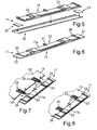
- the multipart constructed additional part 17 comprises a base part 18, which is preferably made of plastic.
- the additional part 17 includes a front cover 19 which is formed as a strip and may be made of sheet metal, for example. The areal dimensions of the cover 19 are dimensioned so that the base part 18 is completely covered on the front side.
- the additional part 17 has lateral caps 20 and 21 which cover the base part 18 laterally.
- the caps 20 and 21 are preferably made of the same material as the front cover 19 and are preferably welded or glued to the cover 19.
- Fig. 6 is the assembled state of the separate items of the additional part 17, as it is in Fig. 5 shown is shown.
- the caps can be seen on the side short and narrow edges of the additional part 17 and thus form the outer end.
- the cover 19 and the caps 20, 21 are preferably made of stainless steel.
- connecting elements 22 and 23 are formed, in particular integrated, which are designed as latching receptacles or plug-in receptacles.
- FIG. 7 As in the presentation according to Fig. 7 in which a partially represented front screen 15 separated from an additional part 17, as shown in FIG Fig. 5 and Fig. 6 is formed is shown, formed on the back 15f connecting elements 24 and 25 engage in the base part-side connecting elements 22 and 23, in particular engage or be plugged.
- Fig. 8 a perspective view of the assembled state completely shown in the end position between the front screen 15 and the additional part 17 is shown. Furthermore, guide webs 26, 27 and 28 are formed on the base part 18 and extend upward above the upper boundary edge 17a extend and, as in Fig. 8 can be seen in the assembled final state, the windscreen 15 engage behind and rest against the back 15f.
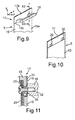
- Fig. 9 another embodiment of a door 5 is shown.
- the additional part 17 is not positioned adjacent to a lower boundary edge 15c of the front screen 15, but is disposed adjacent to the upper boundary edge 15b.
- the door handle 16 is attached to the additional part 17, so that the additional part 17 serves here as a carrier for another functional part, namely the door handle 16.
- a flush arrangement of the front side 17b is formed with the front side 15a. Again, no overlap in the y direction between the additional part 17 and the front screen 15 is provided on the front side. Again, the additional part 17 extends in the x-direction and thus in the width of the door 5 across the width of the windshield 15. Mounting options of the additional part 17 in particular on the windscreen 15 may be provided analogously to the already explained embodiments. Again, the additional part 17 may be formed as a one-piece solid part of a material or as a multi-part component.
- Fig. 10 is shown in a perspective view of the door 5 with the door handle 16 removed, in which case then bushings 29 and 30 can be seen for the fasteners.
- Fig. 11 is a sectional view of the view in Fig. 9 shown along the section line XI-XI. It can be seen that the base part 18 is connected to the cover 19 by an adhesive bond, in particular an adhesive tape 31.
- a fastener designed as a screw 32 extends through a hole in the connecting element 25 and the connecting element 23 and also extends through the opening 30, in order then to be screwed to the door handle 16.
- a door can be used as a hinged door (swiveling around a horizontal axis) or as a revolving door (pivotable about a vertical axis) may be formed.
Landscapes
- Engineering & Computer Science (AREA)
- Chemical & Material Sciences (AREA)
- Combustion & Propulsion (AREA)
- Mechanical Engineering (AREA)
- General Engineering & Computer Science (AREA)
- Electric Ovens (AREA)
Applications Claiming Priority (2)
| Application Number | Priority Date | Filing Date | Title |
|---|---|---|---|
| DE102014205111 | 2014-03-19 | ||
| DE102014216552.0A DE102014216552A1 (de) | 2014-03-19 | 2014-08-20 | Tür für ein Haushaltsgerät mit einer Frontscheibe und einem Zusatzteil sowie Haushaltsgerät mit einer Tür |
Publications (1)
| Publication Number | Publication Date |
|---|---|
| EP2921785A1 true EP2921785A1 (fr) | 2015-09-23 |
Family
ID=52595223
Family Applications (1)
| Application Number | Title | Priority Date | Filing Date |
|---|---|---|---|
| EP15157405.0A Withdrawn EP2921785A1 (fr) | 2014-03-19 | 2015-03-03 | Porte d'appareil ménager dotée d'une vitre frontale et d'une pièce accessoire et appareil ménager doté d'une porte |
Country Status (2)
| Country | Link |
|---|---|
| EP (1) | EP2921785A1 (fr) |
| DE (1) | DE102014216552A1 (fr) |
Citations (9)
| Publication number | Priority date | Publication date | Assignee | Title |
|---|---|---|---|---|
| EP0010829A1 (fr) * | 1978-10-26 | 1980-05-14 | Mills Products Inc. | Regard de porte de four |
| EP1507034A2 (fr) * | 2003-08-14 | 2005-02-16 | Gemtron Corporation | Portes d'appareils |
| US20060219234A1 (en) * | 2005-03-29 | 2006-10-05 | Maytag Corp. | Door assembly for a cooking appliance |
| EP1867927A2 (fr) * | 2006-06-13 | 2007-12-19 | Electrolux Home Products Corporation N.V. | Porte d'un four de cuisson, en particulier un four de cuisson ménager, ainsi que procédé de fabrication |
| US20090194090A1 (en) * | 2008-02-05 | 2009-08-06 | Samsung Electronics Co., Ltd. | Oven |
| CN201463016U (zh) * | 2009-06-06 | 2010-05-12 | 广东新宝电器股份有限公司 | 电烤箱门结构 |
| WO2011076657A2 (fr) | 2009-12-23 | 2011-06-30 | Arcelik Anonim Sirketi | Four dans lequel l'air est évacué par la poignée de porte |
| DE102010043341A1 (de) * | 2010-11-03 | 2012-05-03 | BSH Bosch und Siemens Hausgeräte GmbH | Backofen sowie Backofentür |
| JP2013036636A (ja) * | 2011-08-04 | 2013-02-21 | Sharp Corp | 加熱調理器 |
-
2014
- 2014-08-20 DE DE102014216552.0A patent/DE102014216552A1/de not_active Withdrawn
-
2015
- 2015-03-03 EP EP15157405.0A patent/EP2921785A1/fr not_active Withdrawn
Patent Citations (9)
| Publication number | Priority date | Publication date | Assignee | Title |
|---|---|---|---|---|
| EP0010829A1 (fr) * | 1978-10-26 | 1980-05-14 | Mills Products Inc. | Regard de porte de four |
| EP1507034A2 (fr) * | 2003-08-14 | 2005-02-16 | Gemtron Corporation | Portes d'appareils |
| US20060219234A1 (en) * | 2005-03-29 | 2006-10-05 | Maytag Corp. | Door assembly for a cooking appliance |
| EP1867927A2 (fr) * | 2006-06-13 | 2007-12-19 | Electrolux Home Products Corporation N.V. | Porte d'un four de cuisson, en particulier un four de cuisson ménager, ainsi que procédé de fabrication |
| US20090194090A1 (en) * | 2008-02-05 | 2009-08-06 | Samsung Electronics Co., Ltd. | Oven |
| CN201463016U (zh) * | 2009-06-06 | 2010-05-12 | 广东新宝电器股份有限公司 | 电烤箱门结构 |
| WO2011076657A2 (fr) | 2009-12-23 | 2011-06-30 | Arcelik Anonim Sirketi | Four dans lequel l'air est évacué par la poignée de porte |
| DE102010043341A1 (de) * | 2010-11-03 | 2012-05-03 | BSH Bosch und Siemens Hausgeräte GmbH | Backofen sowie Backofentür |
| JP2013036636A (ja) * | 2011-08-04 | 2013-02-21 | Sharp Corp | 加熱調理器 |
Also Published As
| Publication number | Publication date |
|---|---|
| DE102014216552A1 (de) | 2015-09-24 |
Similar Documents
| Publication | Publication Date | Title |
|---|---|---|
| DE4218007A1 (de) | Gehäuse | |
| DE202009013452U1 (de) | Ein gelenkfreier Scheibenwischer | |
| EP3841329A1 (fr) | Porte pour un appareil de cuisson pourvue d'une armature séparée pourvue d'une poignée encastrée, et appareil de cuisson pourvu d'une porte | |
| EP2553343B1 (fr) | Porte de four et procédé pour fixer un habillage de porte à une telle porte de four | |
| DE19803978B4 (de) | Kraftfahrzeugtürkonstruktion | |
| WO2006042591A1 (fr) | Boitier ou unite de reception de type baie, a baguette de marquage | |
| DE202010018448U1 (de) | Tragstruktur für ein Gehäuse eines Haushaltsgeräts | |
| EP1160513A2 (fr) | Appareil domestique avec panneau de commande frontal | |
| DE102007021938A1 (de) | Kocheinheitsschutzvorrichtung | |
| DE10227562B4 (de) | Abdeckrahmen für ein elektrisches Installationsgerät | |
| DE19738504C5 (de) | Tür für ein Haushaltsgerät, insbesondere einen Haushaltsgarofen | |
| DE102014216552A1 (de) | Tür für ein Haushaltsgerät mit einer Frontscheibe und einem Zusatzteil sowie Haushaltsgerät mit einer Tür | |
| EP2469189A2 (fr) | Hotte aspirante équipée d'un dispositif de fixation d'un écran à vapeur et procédé de fixation | |
| EP2758718B1 (fr) | Appareil de cuisson avec une porte | |
| EP1612362A1 (fr) | Battant dans un cadre dormant avec un entraînement | |
| EP2141416B1 (fr) | Panneau d'appareils ménagers | |
| EP1526335B1 (fr) | Plaque de cuisson | |
| EP2787282A1 (fr) | Dispositif d'éclairage de l'espace intérieur d'un appareil ménager et appareil ménager doté d'un tel dispositif d'éclairage | |
| EP1726884B1 (fr) | Porte d'un four cuisinière | |
| DE202013102648U1 (de) | Gehäuse zum Aufnehmen von Bauteilen, insbesondere von elektronischen Baugruppen, Bauelementen und dergleichen | |
| EP1918645B1 (fr) | Porte d'un four de cuisson | |
| DE102008013004A1 (de) | Anordnung mit einem Kochfeld und einer Arbeitsplatte | |
| EP2602554A1 (fr) | Porte pour un appareil ménager, appareil ménager doté d'une porte et procédé de montage d'un profilé de porte | |
| EP0790470A2 (fr) | Appareil de cuisson avec une poignée pour sa porte | |
| EP2606284B1 (fr) | Hotte aspirante |
Legal Events
| Date | Code | Title | Description |
|---|---|---|---|
| PUAI | Public reference made under article 153(3) epc to a published international application that has entered the european phase |
Free format text: ORIGINAL CODE: 0009012 |
|
| AK | Designated contracting states |
Kind code of ref document: A1 Designated state(s): AL AT BE BG CH CY CZ DE DK EE ES FI FR GB GR HR HU IE IS IT LI LT LU LV MC MK MT NL NO PL PT RO RS SE SI SK SM TR |
|
| AX | Request for extension of the european patent |
Extension state: BA ME |
|
| 17P | Request for examination filed |
Effective date: 20160323 |
|
| RBV | Designated contracting states (corrected) |
Designated state(s): AL AT BE BG CH CY CZ DE DK EE ES FI FR GB GR HR HU IE IS IT LI LT LU LV MC MK MT NL NO PL PT RO RS SE SI SK SM TR |
|
| 17Q | First examination report despatched |
Effective date: 20180119 |
|
| GRAP | Despatch of communication of intention to grant a patent |
Free format text: ORIGINAL CODE: EPIDOSNIGR1 |
|
| INTG | Intention to grant announced |
Effective date: 20200228 |
|
| STAA | Information on the status of an ep patent application or granted ep patent |
Free format text: STATUS: THE APPLICATION IS DEEMED TO BE WITHDRAWN |
|
| 18D | Application deemed to be withdrawn |
Effective date: 20200710 |