EP2921792A1 - Climatiseur de type intégré et structure de support pour élément de tuyauterie - Google Patents
Climatiseur de type intégré et structure de support pour élément de tuyauterie Download PDFInfo
- Publication number
- EP2921792A1 EP2921792A1 EP15158517.1A EP15158517A EP2921792A1 EP 2921792 A1 EP2921792 A1 EP 2921792A1 EP 15158517 A EP15158517 A EP 15158517A EP 2921792 A1 EP2921792 A1 EP 2921792A1
- Authority
- EP
- European Patent Office
- Prior art keywords
- piping
- vibration
- indoor
- support structure
- holding member
- Prior art date
- Legal status (The legal status is an assumption and is not a legal conclusion. Google has not performed a legal analysis and makes no representation as to the accuracy of the status listed.)
- Withdrawn
Links
Images


Classifications
-
- F—MECHANICAL ENGINEERING; LIGHTING; HEATING; WEAPONS; BLASTING
- F24—HEATING; RANGES; VENTILATING
- F24F—AIR-CONDITIONING; AIR-HUMIDIFICATION; VENTILATION; USE OF AIR CURRENTS FOR SCREENING
- F24F1/00—Room units for air-conditioning, e.g. separate or self-contained units or units receiving primary air from a central station
- F24F1/02—Self-contained room units for air-conditioning, i.e. with all apparatus for treatment installed in a common casing
- F24F1/022—Self-contained room units for air-conditioning, i.e. with all apparatus for treatment installed in a common casing comprising a compressor cycle
-
- F—MECHANICAL ENGINEERING; LIGHTING; HEATING; WEAPONS; BLASTING
- F16—ENGINEERING ELEMENTS AND UNITS; GENERAL MEASURES FOR PRODUCING AND MAINTAINING EFFECTIVE FUNCTIONING OF MACHINES OR INSTALLATIONS; THERMAL INSULATION IN GENERAL
- F16L—PIPES; JOINTS OR FITTINGS FOR PIPES; SUPPORTS FOR PIPES, CABLES OR PROTECTIVE TUBING; MEANS FOR THERMAL INSULATION IN GENERAL
- F16L5/00—Devices for use where pipes, cables or protective tubing pass through walls or partitions
- F16L5/02—Sealing
- F16L5/10—Sealing by using sealing rings or sleeves only
-
- F—MECHANICAL ENGINEERING; LIGHTING; HEATING; WEAPONS; BLASTING
- F16—ENGINEERING ELEMENTS AND UNITS; GENERAL MEASURES FOR PRODUCING AND MAINTAINING EFFECTIVE FUNCTIONING OF MACHINES OR INSTALLATIONS; THERMAL INSULATION IN GENERAL
- F16L—PIPES; JOINTS OR FITTINGS FOR PIPES; SUPPORTS FOR PIPES, CABLES OR PROTECTIVE TUBING; MEANS FOR THERMAL INSULATION IN GENERAL
- F16L55/00—Devices or appurtenances for use in, or in connection with, pipes or pipe systems
- F16L55/02—Energy absorbers; Noise absorbers
- F16L55/033—Noise absorbers
- F16L55/035—Noise absorbers in the form of specially adapted hangers or supports
-
- F—MECHANICAL ENGINEERING; LIGHTING; HEATING; WEAPONS; BLASTING
- F24—HEATING; RANGES; VENTILATING
- F24F—AIR-CONDITIONING; AIR-HUMIDIFICATION; VENTILATION; USE OF AIR CURRENTS FOR SCREENING
- F24F1/00—Room units for air-conditioning, e.g. separate or self-contained units or units receiving primary air from a central station
- F24F1/06—Separate outdoor units, e.g. outdoor unit to be linked to a separate room comprising a compressor and a heat exchanger
- F24F1/26—Refrigerant piping
- F24F1/34—Protection means thereof, e.g. covers for refrigerant pipes
Definitions
- the present invention relates to a piping member support structure for an indoor and outdoor integrated type air conditioner in which an indoor unit and an outdoor unit are integrated, and an indoor and outdoor air conditioner including the piping member support structure.
- Patent Literature 1 shows an indoor and outdoor integrated type air conditioner in which an indoor unit and an outdoor unit are integrated adjacently to each other in the horizontal direction.
- An indoor and outdoor integrated type air conditioner like this has a structure in which the indoor unit and the outdoor unit are partitioned by a partition plate, and refrigerant piping connecting the indoor unit and the outdoor unit penetrates through the partition plate.
- Fig. 2 of Patent Literature 1 illustrates a piping member support structure in which putty (a sealant or the like) is filled in a cutout portion as the prior art, in order to prevent wind and rain from outside entering an indoor unit side from the cutout portion in the partition plate.
- putty a sealant or the like
- a piping member support structure in which putty is filled in the cutout portion where refrigerant piping passes as above not only requires a lot of effort in assembly thereof, but also causes a fear of reduction in sealability, because the filled state of the putty varies depending on the level of the skill of a worker who fills the putty.
- FIG. 3 and Fig. 4 in Patent Literature 1 illustrate the structure in which at an edge portion of an indoor cover which is fitted from above the partition plate, a hood-shaped protruded portion which is bulged to cover an upper part of the cutout portion, and a folded portion that is folded downward from the protruded portion are provided so that water droplets at a time of rainfall are prevented from entering from the cutout portion, as an improvement.
- the condenser that condenses the refrigerant is cooled by a cooling fan inside the outdoor unit, and there is the trouble that hot air that finishes cooling the condenser blows to the indoor unit side through the cutout portion through which the aforementioned refrigerant piping is inserted, and reduces the cooling efficiency of the evaporator installed inside the indoor unit.
- the present invention is made in the light of the above described circumstances, and has an object to provide a piping member support structure for an indoor and an outdoor integrated type air conditioner capable of improving assembly workability and sealability in a penetrated portion for the piping member to a partition member, and preventing vibration of the piping member, outward leakage of condensed water and the like, in an indoor and outdoor integrated air conditioner with a structure in which the piping member is penetrated through the partition member which partitions an outdoor unit and an indoor unit which are vertically integrated, and an indoor and outdoor integrated air conditioner including the piping member support structure.
- the present invention adopts the following solution.
- a piping member support structure for an indoor and outdoor integrated type air conditioner is a piping member support structure for an indoor and outdoor integrated type air conditioner including an outdoor unit and an indoor unit that are vertically integrated, a partition member that separates the outdoor unit and the indoor unit, and a piping member that connects the outdoor unit and the indoor unit, and penetrates through the partition member, the piping member support structure including a cutout portion in a shape curved inward that is formed at an edge portion of the partition member, and a vibration-proof holding member that is formed of an elastic material and is closely fitted in the cutout portion so as to hold the piping member in a vibration isolating manner, wherein the vibration-proof holding member includes a piping insertion hole through which the piping member is closely inserted, and a cut-through portion that extends to a fitting direction of the vibration-proof holding member from the piping insertion hole, and has two surfaces facing each other, and a spacing dimension between the two surfaces of the cut-through portion is smaller than an inside diameter dimension of the
- the vibration-proof holding member which is formed of an elastic material is closely fitted into the cutout portion in the concave shape which is formed at the edge portion of the partition member which separates the outdoor unit and the indoor unit, and the piping member is held by the vibration-proof holding member in a vibration isolating manner. Therefore, vibration of the compressor which is incorporated in the outdoor unit is prevented from being transmitted to the indoor unit side through the metallic piping member, and the fear of generation of vibration sound, and reduction in durability of the evaporator which is incorporated in the indoor unit side can be eliminated.
- the piping insertion hole which is formed in the vibration-proof holding member communicates with the back surface side of the vibration-proof holding member via the cut-through portion extending to the fitting direction of the vibration-proof holding member. Therefore, even if placement of the piping member passing through the cutout portion is completed, the vibration-proof holding member is easily fitted onto the piping member later, and can be fitted in the cutout portion. Accordingly, workability at the time of assembling the vibration-proof holding member is extremely high.
- the spacing dimension between the two surfaces of the cut-through portion is such a dimension that the piping member can be fitted into the piping insertion hole if the spacing is forcefully opened within the elasticity range of the vibration-proof holding member, and is set to be the dimension smaller than the inside diameter dimension of the piping insertion hole. Therefore, the piping member which is fitted in the piping insertion hole is not disengaged to the cut-through portion side by vibration or the like, and vibration in the horizontal direction (longitudinal and lateral directions) of the piping member is effectively isolated by elasticity of the vibration-proof holding member.
- the piping member support structure for an indoor and outdoor integrated type air conditioner may have a construction wherein an uppermost portion of the cut-through portion in the vibration-proof holding member is a slit portion in which the spacing between the two surfaces is zero, and a wall thickness of the slit portion is set at such a thickness as not to interfere with fitting of the piping member into the piping insertion hole.
- the upper portion of the cut-through portion is closed by the slit portion, and therefore, when the condensed water formed on the surface of the piping member flows down onto the top surface of the vibration-proof holding member, the condensed water can be prevented from flowing down from the cut-through portion with vigor.
- the condensed water leaks downward from the slit portion, and flows downward along the piping member. Therefore, the condensed water is reliably guided to a predetermined position (a drain pan or the like) and can be properly disposed of.
- the upper portion of the cut-through portion is closed by the slit portion, and therefore, flow of air to and from the outdoor unit and the indoor unit can be inhibited. Therefore, for example, hot air generated inside the outdoor unit at the time of a cooling operation can be prevented from flowing in an inside of the indoor unit and reducing the cooling efficiency (heat loss).
- the piping member support structure for an indoor and outdoor integrated type air conditioner may have a construction wherein on a top surface of the vibration-proof holding member, a waterstop wall that surrounds and is spaced from a periphery of the piping insertion hole is vertically provided.
- the condensed water formed on the surface of the piping member flows down onto the top surface of the vibration-proof holding member, the condensed water is blocked by the waterstop wall, and is prevented from flowing. Therefore, the condensed water is passed in an optional direction and can be properly disposed of.
- the piping member support structure for an indoor and outdoor integrated type air conditioner may have a construction wherein on an outer peripheral surface of the vibration-proof holding member, an outer peripheral fitting groove that is fitted onto an inner peripheral edge portion of the cutout portion is formed, at both end portions of the inner peripheral edge portion, engagement hooks that extend toward an inside of the shape curved inward of the cutout portion are formed, and at both end portions of the outer peripheral fitting groove, engagement concave portions with which the engagement hooks are engaged are formed.
- the vibration-proof holding member if the vibration-proof holding member is forced into the cutout portion so that the inner peripheral edge portion of the cutout portion is fitted in the outer peripheral fitting groove of the vibration-proof holding member, the engagement hooks at the inner peripheral edge portion finally engages with the engagement concave portions in the outer peripheral fitting groove, whereby the vibration-proof holding member is positioned to and fitted in the cutout portion.
- the vibration-proof holding member does not disengage from the cutout portion naturally. Accordingly, assembly workability of the vibration-proof holding member is improved, and a holding force of the vibration-proof holding member in the cutout portion can be enhanced.
- the piping member support structure for an indoor and outdoor integrated type air conditioner may have a construction wherein a vertical wall portion along the outer peripheral surface of the vibration-proof holding member is formed in the cutout portion.
- the vertical wall portion provided in the cutout portion is in contact with the outer peripheral surface of the vibration-proof holding member in a planar form, and therefore, vibration of the piping member is stably received by the cutout portion in a wide area through the vibration-proof holding member and the vertical wall portion. Therefore, vibration of the piping member can be isolated more effectively.
- an indoor and outdoor integrated type air conditioner includes an outdoor unit and an indoor unit that are vertically integrated, a partition member that separates the outdoor unit and the indoor unit, and any one of the above described piping member support structures.
- the vibration-proof holding member which is an elastic body is closely fitted in the cutout portion formed at the edge portion of the partition member, and the piping member is held by the vibration-proof holding member in a vibration isolating manner. Therefore, vibration of the compressor which is incorporated in the outdoor unit is difficult to transmit to the indoor unit side through the piping member, and generation of vibration sound and reduction in durability of the evaporator can be restrained.
- the piping insertion hole which is formed in the vibration-proof holding member communicates with the back surface side of the vibration-proof holding member through the cut-through portion which extends to the fitting direction of the vibration-proof holding member. Therefore, the vibration-proof holding member can be fitted after the piping member is placed, and assembly workability of the vibration-proof holding member can be made excellent.
- the piping member support structure for an indoor and outdoor integrated type air conditioner according to the present invention, and the indoor and outdoor integrated type air conditioner including the piping member support structure, assembly workability and sealability in the insertion portion of the piping member can be improved, and vibration of the piping member, outward leakage of condensed water and the like can be prevented.
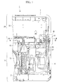
- Fig. 1 is a rear view of an indoor and outdoor unit integrated type air conditioner to which the embodiment of the piping member support structure according to the present invention is applied
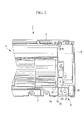
- Fig. 2 is a cross-sectional view of the air conditioner seen from arrows II-II in Fig. 1 .
- a tray-shaped drain pan 2 which is horizontal and rectangular is provided at a lowermost portion thereof, and a similar tray-shaped intermediate frame 3 (a partition member) is also provided in an intermediate portion.
- the drain pan 2 and the intermediate frame 3 are respectively molded from a resin, for example, and construct an air conditioner frame by being connected to each other by metallic angle members or the like (not illustrated) which are vertically disposed at respective four corners of the drain pan 2 and the intermediate frame 3.
- the air conditioner frame is enclosed by an exterior plate 6, a ceiling plate 7, a front plate 8, a back plate (not illustrated), and the like.
- An outdoor unit 11 is installed on the drain pan 2.
- Reference sign 12 shown in Fig. 1 designates a condenser, and reference sign 13 designates a cooling fan.
- the outdoor unit 11 is constructed by including a compression machine (compressor), a control device and the like (not illustrated), in addition to the above components.
- An indoor unit 21 is installed on the intermediate frame 3.
- the indoor unit 21 is constructed by having a vaporizer (an evaporator), a blower (a sirocco fan) and the like which are not illustrated incorporated inside a resin unit box 22.
- the outdoor unit 11 and the indoor unit 21 are vertically integrated, and are separated by the intermediate frame 3.
- Two metallic piping members 26 and 27 that connect the outdoor unit 11 and the indoor unit 21 penetrate through the intermediate frame 3, and a piping member support structure S according to the present invention is applied to a penetration portion.
- the piping members 26 and 27 are respectively a high-pressure refrigerant hose, and a low-pressure refrigerant hose, for example, but any other kinds of piping may be used.
- Fig. 3 is an enlarged view showing the piping member support structure S by enlarging a part III in Fig. 1
- Fig. 4 is a plan view of the piping member support structure S.
- the piping member support structure S has a construction including a cutout portion 31 which is formed at an edge portion of the intermediate frame 3 and has a shape curved inward in plan view, and a vibration isolating block 32 (a vibration-proof holding member) that is closely fitted in the cutout portion 31.
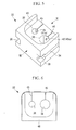
- Figs. 5 to 10 are single component views of the vibration isolating block 32.
- the vibration isolating block 32 is formed of an elastic material such as a rubber, a flexible resin, a silicon resin, and an expandable resin, and is a component that is closely fitted into the cutout portion 31 and has a role of holding the piping members 26 and 27 in a vibration isolating manner.
- the cutout portion 31 presents a shape in which an edge portion of the intermediate frame 3 is cut out into a substantially rectangular shape to curve inward to an inside region of the intermediate frame 3, and as shown in Figs. 3 and 4 , an inner peripheral edge portion 33 of the cutout portion 31 is in a flange shape so that the inner peripheral edge portion 33 is fitted in an outer peripheral fitting groove 34 formed on an outer peripheral surface of the vibration isolating block 32.
- the outer peripheral fitting groove 34 is formed throughout three surfaces that are both left and right side surfaces and a rear surface of the vibration isolating block 32.
- vertical wall portions 35 which stand upright and are formed at both side portions of the cutout portion 31.
- the vertical wall portion 35 continues to an outer peripheral wall 3a (see Figs. 2 and 4 ) of the intermediate frame 3 which is formed into a tray-shape, and is a wall along an outer peripheral surface of the vibration isolating block 32 which is fitted into the cutout portion 31.
- the vertical wall portions 35 are formed on only two sides that face each other of the cutout portion 31, but may be formed throughout an entire perimeter of the inward-curving shape of the cutout portion 31.
- a pair of engagement hooks 37 are formed at both end portions (a forefront portion) of the inner peripheral edge portion 33 in the cutout portion 31.
- the pair of engagement hooks 37 extend toward an inside of the inward-curving shape of the cutout portion 31 to be close to each other.
- thickness dimensions in the horizontal direction and the vertical direction are set to be larger than thickness dimensions in the horizontal and the vertical direction of the inner peripheral edge portion 33.
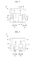
- two vertical piping insertion holes 38 and 39 through which the piping members 26 and 27 are closely inserted, and cut-through portions 41 and 42 (see Figs. 4 , 5 and 8 ) that extend from the piping insertion holes 38 and 39 toward a fitting direction F (see Fig. 4 ) of the vibration isolating block 32 respectively to pass through the vibration isolating block 32 to the back surface side of the vibration isolating block 32 are formed.
- the cut-through portions 41 and 42 respectively have two parallel surfaces 41a and 41a, and 42a and 42a which face each other.
- a spacing dimension w1 between the two surfaces 41a and 41a, and a spacing dimension w2 between the two surfaces 42a and 42a are set to be smaller than inside diameter dimensions d1 and d2 of the piping insertion holes 38 and 39 respectively and to be spaces which allow the piping members 26 and 27 to be fitted into the piping insertion holes 38 and 39 by forcefully opening the cut-through portions 41 and 42 within an elasticity range of the vibration isolating block 32.
- the spacing dimensions w1 and w2 of the two surfaces 41a and 42a are set at approximately 4 mm and 7.5 mm, respectively.
- uppermost portions of the cut-through portions 41 and 42 in the vibration isolating block 32 are slit portions 45 and 46 in which the spaces between the two surfaces 41a and 41a, and 42a and 42a are zero, and in plan view of the vibration isolating block 32, the cut-through portions 41 and 42 are invisible. That is to say, in plan view of the vibration isolating block 32, only the piping insertion holes 38 and 39 and the slit portions 45 and 46 which extends from the piping insertion holes 38 and 39 are visible.
- a wall thickness t (see Fig. 9 ) at portions where the slit portions 45 and 46 are provided is set at such a thickness as not to interfere with fitting of the piping members 26 and 27 into the piping insertion holes 38 and 39, that is, a thickness of approximately 1 to 2 mm, for example, with which the piping members 26 and 27 can turn up the portions where the slit portions 45 and 46 are provided when passing through the cut-through portions 41 and 42.
- a waterstop wall 48 that surrounds and is spaced from peripheries of the piping insertion holes 38 and 39 is vertically provided on a top surface of the vibration isolating block 32.
- the waterstop wall 48 is raised from a front edge portion and both side edge portions of the top surface of the vibration isolating block 32, and presents a channel shape in plan view. Note that the waterstop wall 48 may be also formed at a rear edge portion of the vibration isolating block 32.
- a height of the waterstop wall 48 is set at such an extent as to be able to collect condensed water when the condensed water formed on surfaces of the piping members 26 and 27 which are at a position higher than the vibration isolating block 32 flows downward, that is, at several millimeters to around 1 to 2 centimeters.
- the piping member support structure S is constructed as above.
- the outdoor unit 11 and the indoor unit 21 are respectively assembled onto the drain pan 2 and the intermediate frame 3.
- the vibration isolating block 32 is fitted into the cutout portion 31 of the intermediate frame 3 as shown in Fig. 4 to prevent vibration of the piping members 26 and 27.
- the vibration isolating block 32 is pressed in the fitting direction F so that the inner peripheral edge portion 33 of the cutout portion 31 is inserted in the outer peripheral fitting groove 34 of the vibration isolating block 32 (see Fig. 4 ).
- the cut-through portions 41 and 42 of the vibration isolating block 32 are applied to the piping members 26 and 27, respectively, and are further pressed in the fitting direction F, whereby the piping members 26 and 27 pass through the cut-through portions 41 and 42 and are fitted into the piping insertion holes 38 and 39. Simultaneously therewith, the engagement hooks 37 of the cutout portion 31 engage with the engagement concave portions 36 of the outer peripheral fitting groove 34. Therefore, the vibration isolating block 32 is difficult to disengage from the cutout portion 31.
- the piping members 26 and 27 are held by the piping insertion holes 38 and 39 of the vibration isolating block 32 which is closely fitted in the cutout portion 31 in a vibration isolating manner. Therefore, vibration of the compressor which is incorporated in the outdoor unit 11 is prevented from being transmitted to the indoor unit 21 side through the metallic piping members 26 and 27, and the fears of generation of vibration sound, and reduction in durability of the evaporator (not illustrated) which is incorporated in the indoor unit 21 side can be eliminated.
- the piping insertion holes 38 and 39 which are formed in the vibration isolating block 32 communicates with the back surface side of the vibration isolating block 32 via the cut-through portions 41 and 42 which extend toward the fitting direction F of the vibration isolating block 32. Therefore, even if placement of the piping members 26 and 27 which passes through the cutout portion 31 is completed, the vibration isolating block 32 is easily fitted to the piping members 26 and 27 later, and can be fitted into the cutout portion 31. Accordingly, workability at the time of assembling the vibration isolating block 32 is extremely good.
- the spacing dimensions w1 and w2 of the two surfaces 41a and 42a of the cut-through portions 41 and 42 are set at such dimensions that the piping members 26 and 27 can be fitted into the piping insertion holes 38 and 39 if the cut-through portions 41 and 42 are forcefully opened within the elasticity range of the vibration isolating block 32.
- the spacing dimensions w1 and w2 are set at dimensions smaller than the inside diameter dimensions of the piping insertion holes 38 and 39, and therefore, the piping members 26 and 27 which are fitted in the piping insertion holes 38 and 39 are not disengaged to the cut-through portions 41 and 42 sides by vibration or the like. Accordingly, the vibration in the horizontal direction (the longitudinal and lateral directions) of the piping members 26 and 27 can be effectively isolated by the elasticity of the vibration isolating block 32.
- the uppermost portions of the cut-through portions 41 and 42 in the vibration isolating block 32 are the slit portions 45 and 46 where the spaces between the facing two surfaces 41a and 42a are zero.
- the wall thickness t (see Fig. 9 ) of the slit portions 45 and 46 is set at such a thickness as not to interfere the piping members 26 and 27 being fitted into the piping insertion holes 38 and 39.
- the upper portions of the cut-through portions 41 and 42 are closed by the slit portions 45 and 46.
- the condensed water formed on the surfaces of the piping members 26 and 27 flow down onto the top surface of the vibration isolating block 32, the condensed water is prevented from flowing downward with vigor from the cut-through portions 41 and 42.
- the condensed water leaks downward little by little from the slit portions 45 and 46, and flows downward along the piping members 26 and 27. Therefore, the condensed water is reliably guided to a predetermined position (the drain pan 2 and the like) and can be properly disposed of.
- the upper portions of the cut-through portions 41 and 42 are closed by the slit portions 45 and 46, and therefore, air can be inhibited from flowing to and from the outdoor unit 11 and the indoor unit 21. Therefore, hot air which is generated inside the outdoor unit 11 at the time of a cooling operation can be effectively prevented from flowing into the indoor unit 21 and reducing cooling efficiency (heat loss).
- the waterstop wall 48 which surrounds and is spaced from the peripheries of the piping insertion holes 38 and 39 is vertically provided. Therefore, when the condensed water formed on the surfaces of the piping members 26 and 27 flows down onto the top surface of the vibration isolating block 32, the condensed water is blocked by the waterstop wall 48, and is prevented from flowing. Therefore, the condensed water is passed in an optional direction and can be properly disposed of.
- the outer peripheral fitting groove 34 which is fitted onto the inner peripheral edge portion 33 of the cutout portion 31 is formed.
- the engagement hooks 37 extending toward the inside in the shape curved inward of the cutout portion 31 are formed.
- the engagement concave portions 36 with which the engagement hooks 37 are engaged are formed.
- the vibration isolating block 32 is forced into the cutout portion 31 so that the inner peripheral edge portion 33 of the cutout portion 31 is fitted in the outer peripheral fitting groove 34 of the vibration isolating block 32, the engagement hooks 37 at the inner peripheral edge portion 33 finally engages with the engagement concave portions 36 of the outer peripheral fitting groove 34, whereby the vibration isolating block 32 is positioned to and fitted in the cutout portion 31.
- the vibration isolating block 32 does not naturally disengage from the cutout portion 31. Accordingly, assembling workability of the vibration isolating block 32 is improved, and the holding force of the vibration isolating block 32 in the cutout portion 31 can be remarkably enhanced.
- the vertical wall portions 35 are formed, and the vertical wall portions 35 are in contact with the outer peripheral surface of the vibration isolating block 32 in a planar form. Therefore, vibration of the piping members 26 and 27 are stably received by the cutout portion 31 in a wide area through the vibration isolating block 32 and the vertical wall portion 35. Therefore, vibration of the piping members 26 and 27 can be more effectively controlled.
- the vibration isolating block 32 which is an elastic body is closely fitted in the cutout portion 31 which is formed at the edge portion of the intermediate frame 3 which is the partition member, and the piping members 26 and 27 are held by the vibration isolating block 32 in a vibration isolating manner. Therefore, vibration of the compressor which is incorporated in the outdoor unit 11 is difficult to transmit to the indoor unit 21 side through the piping members 26 and 27, and generation of vibration sound and reduction in durability of the evaporator can be restrained.
- the piping member support structure of the indoor and outdoor integrated type air conditioner according to the present embodiment, and the indoor and outdoor integrated type air conditioner including the piping member support structure, assembly workability and sealability in the penetration portion (the cutout portion 31) for the piping members 26 and 27 to the partition member can be improved, and vibration of the piping members 26 and 27, outward leakage of the condensed water and the like can be prevented in the indoor and outdoor integrated type air conditioner 1 with the structure in which the piping members 26 and 27 are penetrated through the partition member (the intermediate frame 3) which separates the outdoor unit 11 and the indoor unit 21 which are vertically integrated.
- the example is described, which applies the piping member support structure according to the present invention to the portion where the two piping members 26 and 27 penetrate through the intermediate frame 3 which separates the outdoor unit 11 and the indoor unit 21 which construct the indoor and outdoor integrated type air conditioner 1, but the piping member support structure according to the present invention also can be applied to other places if those places have similar structural parts.
- the numbers, use purpose and the like of the piping members 26 and 27 are not limited to those in the above described embodiment.
Landscapes
- Engineering & Computer Science (AREA)
- General Engineering & Computer Science (AREA)
- Mechanical Engineering (AREA)
- Chemical & Material Sciences (AREA)
- Combustion & Propulsion (AREA)
- Vibration Prevention Devices (AREA)
- Air Filters, Heat-Exchange Apparatuses, And Housings Of Air-Conditioning Units (AREA)
Applications Claiming Priority (1)
| Application Number | Priority Date | Filing Date | Title |
|---|---|---|---|
| JP2014056553A JP2015178928A (ja) | 2014-03-19 | 2014-03-19 | 内外一体型空気調和機の配管部材支持構造、およびこれを備えた内外一体型空気調和機 |
Publications (1)
| Publication Number | Publication Date |
|---|---|
| EP2921792A1 true EP2921792A1 (fr) | 2015-09-23 |
Family
ID=52684024
Family Applications (1)
| Application Number | Title | Priority Date | Filing Date |
|---|---|---|---|
| EP15158517.1A Withdrawn EP2921792A1 (fr) | 2014-03-19 | 2015-03-10 | Climatiseur de type intégré et structure de support pour élément de tuyauterie |
Country Status (2)
| Country | Link |
|---|---|
| EP (1) | EP2921792A1 (fr) |
| JP (1) | JP2015178928A (fr) |
Cited By (14)
| Publication number | Priority date | Publication date | Assignee | Title |
|---|---|---|---|---|
| CN107023716A (zh) * | 2016-01-29 | 2017-08-08 | 翰昂汽车零部件有限公司 | 用于保持流体管路端部的固定元件、装置和方法 |
| CN107192044A (zh) * | 2017-06-08 | 2017-09-22 | 太仓市思卡拓机械科技有限公司 | 一种便于安装的空调外机架 |
| WO2021103188A1 (fr) * | 2019-11-29 | 2021-06-03 | 广东美的制冷设备有限公司 | Ensemble d'amortissement pour climatiseur, et climatiseur |
| WO2021184512A1 (fr) * | 2020-03-20 | 2021-09-23 | 广东美的制冷设备有限公司 | Ensemble d'étanchéité et climatiseur intégré |
| DE102020206182A1 (de) | 2020-05-15 | 2021-11-18 | Dometic Sweden Ab | Klimaanlageneinheit |
| EP4030112A4 (fr) * | 2019-11-19 | 2022-11-02 | GD Midea Heating & Ventilating Equipment Co., Ltd. | Contenant du type boîtier étanche, machine principale de dispositif de commutation de récupération de chaleur, et dispositif de réfrigération |
| USD1010080S1 (en) | 2020-05-15 | 2024-01-02 | Dometic Sweden Ab | Housing for air conditioning apparatus |
| USD1057118S1 (en) | 2021-08-16 | 2025-01-07 | Dometic Sweden Ab | Housing for a heat exchanger |
| US12233682B2 (en) | 2018-06-18 | 2025-02-25 | Dometic Sweden Ab | Heating, ventilation and air conditioning system with illumination |
| CN119532842A (zh) * | 2023-08-30 | 2025-02-28 | 广东美的制冷设备有限公司 | 空调器 |
| WO2025045154A1 (fr) * | 2023-08-30 | 2025-03-06 | 芜湖美智空调设备有限公司 | Climatiseur |
| US12264874B2 (en) | 2018-06-18 | 2025-04-01 | Dometic Sweden Ab | Heating, ventilation and air conditioning system with illumination |
| US12291078B2 (en) | 2020-05-15 | 2025-05-06 | Dometic Sweden Ab | Air conditioning unit |
| US12377705B2 (en) | 2020-05-15 | 2025-08-05 | Dometic Sweden Ab | Air conditioning unit |
Citations (6)
| Publication number | Priority date | Publication date | Assignee | Title |
|---|---|---|---|---|
| US4268947A (en) * | 1977-08-29 | 1981-05-26 | Carrier Corporation | Method of securing a capillary tube passing through a wall |
| JPS6227784A (ja) | 1985-07-18 | 1987-02-05 | エステイ−シ− ピ−エルシ− | ホログラフイ−における光学的四波混合方法 |
| EP0580130A1 (fr) * | 1992-07-21 | 1994-01-26 | Ichikoh Industries Limited | Traversée pour conducteurs électriques |
| US7032616B1 (en) * | 2005-03-10 | 2006-04-25 | Calhoun Darrel R | Gas and liquid storage tank dome shell protective cover |
| DE202006007921U1 (de) * | 2006-04-28 | 2007-08-30 | Liebherr-Hausgeräte Lienz Gmbh | Kühl- und/oder Gefriergerät |
| EP1892448A1 (fr) * | 2006-08-25 | 2008-02-27 | Beele Engineering B.V. | Système pour étancher dynamiquement au moins un canal à travers duquel passe un tuyau ou un câble |
-
2014
- 2014-03-19 JP JP2014056553A patent/JP2015178928A/ja active Pending
-
2015
- 2015-03-10 EP EP15158517.1A patent/EP2921792A1/fr not_active Withdrawn
Patent Citations (6)
| Publication number | Priority date | Publication date | Assignee | Title |
|---|---|---|---|---|
| US4268947A (en) * | 1977-08-29 | 1981-05-26 | Carrier Corporation | Method of securing a capillary tube passing through a wall |
| JPS6227784A (ja) | 1985-07-18 | 1987-02-05 | エステイ−シ− ピ−エルシ− | ホログラフイ−における光学的四波混合方法 |
| EP0580130A1 (fr) * | 1992-07-21 | 1994-01-26 | Ichikoh Industries Limited | Traversée pour conducteurs électriques |
| US7032616B1 (en) * | 2005-03-10 | 2006-04-25 | Calhoun Darrel R | Gas and liquid storage tank dome shell protective cover |
| DE202006007921U1 (de) * | 2006-04-28 | 2007-08-30 | Liebherr-Hausgeräte Lienz Gmbh | Kühl- und/oder Gefriergerät |
| EP1892448A1 (fr) * | 2006-08-25 | 2008-02-27 | Beele Engineering B.V. | Système pour étancher dynamiquement au moins un canal à travers duquel passe un tuyau ou un câble |
Cited By (20)
| Publication number | Priority date | Publication date | Assignee | Title |
|---|---|---|---|---|
| CN107023716A (zh) * | 2016-01-29 | 2017-08-08 | 翰昂汽车零部件有限公司 | 用于保持流体管路端部的固定元件、装置和方法 |
| CN107023716B (zh) * | 2016-01-29 | 2019-12-20 | 翰昂汽车零部件有限公司 | 用于保持流体管路端部的固定元件、装置和方法 |
| CN107192044A (zh) * | 2017-06-08 | 2017-09-22 | 太仓市思卡拓机械科技有限公司 | 一种便于安装的空调外机架 |
| US12264874B2 (en) | 2018-06-18 | 2025-04-01 | Dometic Sweden Ab | Heating, ventilation and air conditioning system with illumination |
| US12233682B2 (en) | 2018-06-18 | 2025-02-25 | Dometic Sweden Ab | Heating, ventilation and air conditioning system with illumination |
| EP4030112A4 (fr) * | 2019-11-19 | 2022-11-02 | GD Midea Heating & Ventilating Equipment Co., Ltd. | Contenant du type boîtier étanche, machine principale de dispositif de commutation de récupération de chaleur, et dispositif de réfrigération |
| US20230027551A1 (en) * | 2019-11-19 | 2023-01-26 | Gd Midea Heating & Ventilating Equipment Co., Ltd. | Sealed box container, main machine of heat recovery switching device, and refrigeration device |
| US11913670B2 (en) * | 2019-11-19 | 2024-02-27 | Gd Midea Heating & Ventilating Equipment Co., Ltd. | Sealed box container, main machine of heat recovery switching device, and refrigeration device |
| WO2021103188A1 (fr) * | 2019-11-29 | 2021-06-03 | 广东美的制冷设备有限公司 | Ensemble d'amortissement pour climatiseur, et climatiseur |
| WO2021184512A1 (fr) * | 2020-03-20 | 2021-09-23 | 广东美的制冷设备有限公司 | Ensemble d'étanchéité et climatiseur intégré |
| USD1053326S1 (en) | 2020-05-15 | 2024-12-03 | Dometic Sweden Ab | Air conditioning housing |
| USD1053327S1 (en) | 2020-05-15 | 2024-12-03 | Dometic Sweden Ab | Housing portion for air conditioning apparatus |
| USD1010080S1 (en) | 2020-05-15 | 2024-01-02 | Dometic Sweden Ab | Housing for air conditioning apparatus |
| DE102020206182A1 (de) | 2020-05-15 | 2021-11-18 | Dometic Sweden Ab | Klimaanlageneinheit |
| US12291078B2 (en) | 2020-05-15 | 2025-05-06 | Dometic Sweden Ab | Air conditioning unit |
| US12377705B2 (en) | 2020-05-15 | 2025-08-05 | Dometic Sweden Ab | Air conditioning unit |
| USD1114953S1 (en) | 2020-05-15 | 2026-02-24 | Dometic Sweden Ab | Housing for air conditioning apparatus |
| USD1057118S1 (en) | 2021-08-16 | 2025-01-07 | Dometic Sweden Ab | Housing for a heat exchanger |
| CN119532842A (zh) * | 2023-08-30 | 2025-02-28 | 广东美的制冷设备有限公司 | 空调器 |
| WO2025045154A1 (fr) * | 2023-08-30 | 2025-03-06 | 芜湖美智空调设备有限公司 | Climatiseur |
Also Published As
| Publication number | Publication date |
|---|---|
| JP2015178928A (ja) | 2015-10-08 |
Similar Documents
| Publication | Publication Date | Title |
|---|---|---|
| EP2921792A1 (fr) | Climatiseur de type intégré et structure de support pour élément de tuyauterie | |
| CN103917829B (zh) | 空调装置的室外机 | |
| US11112131B2 (en) | Heat source unit with corrugated bottom plate | |
| EP2977689A2 (fr) | Unité intérieure de climatiseur | |
| US10352573B2 (en) | Air-conditioning apparatus having decorative panel mount structure and indoor unit having the same | |
| US9510073B2 (en) | Air conditioner having an audio collecting device | |
| CN204880445U (zh) | 空调室外机及空调系统 | |
| EP2682687A2 (fr) | Protection d'évent | |
| EP3048378A1 (fr) | Dispositif extérieur pour climatiseur | |
| US10119746B2 (en) | Indoor unit and air-conditioning apparatus | |
| US10443902B2 (en) | Outdoor device for an air conditioner | |
| KR20140000929A (ko) | 냉장고 야채실의 과진공 방지장치 및 이를 장착한 야채실 | |
| US11371747B2 (en) | Indoor unit of air-conditioning apparatus and air-conditioning apparatus | |
| KR20170002349A (ko) | 공기 조화기의 실외기 | |
| JP6936160B2 (ja) | 空気調和装置の室外機 | |
| CN205980073U (zh) | 空调器室外机的接水盘及空调器室外机 | |
| KR102094901B1 (ko) | 공기 조화기의 실외기 | |
| KR101498073B1 (ko) | 공동주택용 단열재 밀폐장치 | |
| EP3578900B1 (fr) | Unité intérieure de climatiseur et climatiseur | |
| KR20160031231A (ko) | 공기 조화기의 실외기 | |
| KR20160031394A (ko) | 공기 조화기의 실외기 | |
| CN207262681U (zh) | 空调室内机底部面板及空调器 | |
| CN204227797U (zh) | 制冷设备 | |
| KR20160031232A (ko) | 공기 조화기의 실외기 | |
| CN104577784A (zh) | 一种防潮且利于排水的配电柜 |
Legal Events
| Date | Code | Title | Description |
|---|---|---|---|
| PUAI | Public reference made under article 153(3) epc to a published international application that has entered the european phase |
Free format text: ORIGINAL CODE: 0009012 |
|
| AK | Designated contracting states |
Kind code of ref document: A1 Designated state(s): AL AT BE BG CH CY CZ DE DK EE ES FI FR GB GR HR HU IE IS IT LI LT LU LV MC MK MT NL NO PL PT RO RS SE SI SK SM TR |
|
| AX | Request for extension of the european patent |
Extension state: BA ME |
|
| 17P | Request for examination filed |
Effective date: 20160323 |
|
| RBV | Designated contracting states (corrected) |
Designated state(s): AL AT BE BG CH CY CZ DE DK EE ES FI FR GB GR HR HU IE IS IT LI LT LU LV MC MK MT NL NO PL PT RO RS SE SI SK SM TR |
|
| STAA | Information on the status of an ep patent application or granted ep patent |
Free format text: STATUS: EXAMINATION IS IN PROGRESS |
|
| RAP1 | Party data changed (applicant data changed or rights of an application transferred) |
Owner name: MITSUBISHI HEAVY INDUSTRIES THERMAL SYSTEMS, LTD. |
|
| 17Q | First examination report despatched |
Effective date: 20171205 |
|
| GRAP | Despatch of communication of intention to grant a patent |
Free format text: ORIGINAL CODE: EPIDOSNIGR1 |
|
| STAA | Information on the status of an ep patent application or granted ep patent |
Free format text: STATUS: GRANT OF PATENT IS INTENDED |
|
| INTG | Intention to grant announced |
Effective date: 20190313 |
|
| STAA | Information on the status of an ep patent application or granted ep patent |
Free format text: STATUS: THE APPLICATION IS DEEMED TO BE WITHDRAWN |
|
| 18D | Application deemed to be withdrawn |
Effective date: 20190724 |