EP2921829B1 - Dispositif de mesure de caractéristiques dynamiques pour machine rotative centrifuge, et machine rotative centrifuge - Google Patents
Dispositif de mesure de caractéristiques dynamiques pour machine rotative centrifuge, et machine rotative centrifuge Download PDFInfo
- Publication number
- EP2921829B1 EP2921829B1 EP13855612.1A EP13855612A EP2921829B1 EP 2921829 B1 EP2921829 B1 EP 2921829B1 EP 13855612 A EP13855612 A EP 13855612A EP 2921829 B1 EP2921829 B1 EP 2921829B1
- Authority
- EP
- European Patent Office
- Prior art keywords
- rotation
- magnetic force
- rotor
- mode
- dynamic characteristic
- Prior art date
- Legal status (The legal status is an assumption and is not a legal conclusion. Google has not performed a legal analysis and makes no representation as to the accuracy of the status listed.)
- Not-in-force
Links
Images





Classifications
-
- F—MECHANICAL ENGINEERING; LIGHTING; HEATING; WEAPONS; BLASTING
- F04—POSITIVE - DISPLACEMENT MACHINES FOR LIQUIDS; PUMPS FOR LIQUIDS OR ELASTIC FLUIDS
- F04D—NON-POSITIVE-DISPLACEMENT PUMPS
- F04D27/00—Control, e.g. regulation, of pumps, pumping installations or pumping systems specially adapted for elastic fluids
- F04D27/001—Testing thereof; Determination or simulation of flow characteristics; Stall or surge detection, e.g. condition monitoring
-
- G—PHYSICS
- G01—MEASURING; TESTING
- G01H—MEASUREMENT OF MECHANICAL VIBRATIONS OR ULTRASONIC, SONIC OR INFRASONIC WAVES
- G01H17/00—Measuring mechanical vibrations or ultrasonic, sonic or infrasonic waves, not provided for in the other groups of this subclass
-
- F—MECHANICAL ENGINEERING; LIGHTING; HEATING; WEAPONS; BLASTING
- F04—POSITIVE - DISPLACEMENT MACHINES FOR LIQUIDS; PUMPS FOR LIQUIDS OR ELASTIC FLUIDS
- F04D—NON-POSITIVE-DISPLACEMENT PUMPS
- F04D1/00—Radial-flow pumps, e.g. centrifugal pumps; Helico-centrifugal pumps
-
- F—MECHANICAL ENGINEERING; LIGHTING; HEATING; WEAPONS; BLASTING
- F04—POSITIVE - DISPLACEMENT MACHINES FOR LIQUIDS; PUMPS FOR LIQUIDS OR ELASTIC FLUIDS
- F04D—NON-POSITIVE-DISPLACEMENT PUMPS
- F04D1/00—Radial-flow pumps, e.g. centrifugal pumps; Helico-centrifugal pumps
- F04D1/06—Multi-stage pumps
-
- F—MECHANICAL ENGINEERING; LIGHTING; HEATING; WEAPONS; BLASTING
- F04—POSITIVE - DISPLACEMENT MACHINES FOR LIQUIDS; PUMPS FOR LIQUIDS OR ELASTIC FLUIDS
- F04D—NON-POSITIVE-DISPLACEMENT PUMPS
- F04D15/00—Control, e.g. regulation, of pumps, pumping installations or systems
- F04D15/0088—Testing machines
-
- F—MECHANICAL ENGINEERING; LIGHTING; HEATING; WEAPONS; BLASTING
- F04—POSITIVE - DISPLACEMENT MACHINES FOR LIQUIDS; PUMPS FOR LIQUIDS OR ELASTIC FLUIDS
- F04D—NON-POSITIVE-DISPLACEMENT PUMPS
- F04D17/00—Radial-flow pumps, e.g. centrifugal pumps; Helico-centrifugal pumps
- F04D17/08—Centrifugal pumps
- F04D17/10—Centrifugal pumps for compressing or evacuating
-
- F—MECHANICAL ENGINEERING; LIGHTING; HEATING; WEAPONS; BLASTING
- F04—POSITIVE - DISPLACEMENT MACHINES FOR LIQUIDS; PUMPS FOR LIQUIDS OR ELASTIC FLUIDS
- F04D—NON-POSITIVE-DISPLACEMENT PUMPS
- F04D29/00—Details, component parts, or accessories
- F04D29/66—Combating cavitation, whirls, noise, vibration or the like; Balancing
-
- G—PHYSICS
- G01—MEASURING; TESTING
- G01H—MEASUREMENT OF MECHANICAL VIBRATIONS OR ULTRASONIC, SONIC OR INFRASONIC WAVES
- G01H1/00—Measuring characteristics of vibrations in solids by using direct conduction to the detector
- G01H1/003—Measuring characteristics of vibrations in solids by using direct conduction to the detector of rotating machines
- G01H1/006—Measuring characteristics of vibrations in solids by using direct conduction to the detector of rotating machines of the rotor of turbo machines
-
- G—PHYSICS
- G01—MEASURING; TESTING
- G01M—TESTING STATIC OR DYNAMIC BALANCE OF MACHINES OR STRUCTURES; TESTING OF STRUCTURES OR APPARATUS, NOT OTHERWISE PROVIDED FOR
- G01M1/00—Testing static or dynamic balance of machines or structures
- G01M1/14—Determining imbalance
- G01M1/16—Determining imbalance by oscillating or rotating the body to be tested
- G01M1/22—Determining imbalance by oscillating or rotating the body to be tested and converting vibrations due to imbalance into electric variables
-
- G—PHYSICS
- G01—MEASURING; TESTING
- G01M—TESTING STATIC OR DYNAMIC BALANCE OF MACHINES OR STRUCTURES; TESTING OF STRUCTURES OR APPARATUS, NOT OTHERWISE PROVIDED FOR
- G01M7/00—Vibration-testing of structures; Shock-testing of structures
- G01M7/02—Vibration-testing by means of a shake table
- G01M7/04—Monodirectional test stands
- G01M7/045—Monodirectional test stands in a circular direction
-
- G—PHYSICS
- G01—MEASURING; TESTING
- G01M—TESTING STATIC OR DYNAMIC BALANCE OF MACHINES OR STRUCTURES; TESTING OF STRUCTURES OR APPARATUS, NOT OTHERWISE PROVIDED FOR
- G01M99/00—Subject matter not provided for in other groups of this subclass
-
- H—ELECTRICITY
- H01—ELECTRIC ELEMENTS
- H01F—MAGNETS; INDUCTANCES; TRANSFORMERS; SELECTION OF MATERIALS FOR THEIR MAGNETIC PROPERTIES
- H01F7/00—Magnets
- H01F7/06—Electromagnets; Actuators including electromagnets
- H01F7/064—Circuit arrangements for actuating electromagnets
-
- H—ELECTRICITY
- H01—ELECTRIC ELEMENTS
- H01F—MAGNETS; INDUCTANCES; TRANSFORMERS; SELECTION OF MATERIALS FOR THEIR MAGNETIC PROPERTIES
- H01F7/00—Magnets
- H01F7/06—Electromagnets; Actuators including electromagnets
- H01F7/20—Electromagnets; Actuators including electromagnets without armatures
-
- F—MECHANICAL ENGINEERING; LIGHTING; HEATING; WEAPONS; BLASTING
- F04—POSITIVE - DISPLACEMENT MACHINES FOR LIQUIDS; PUMPS FOR LIQUIDS OR ELASTIC FLUIDS
- F04D—NON-POSITIVE-DISPLACEMENT PUMPS
- F04D17/00—Radial-flow pumps, e.g. centrifugal pumps; Helico-centrifugal pumps
- F04D17/08—Centrifugal pumps
- F04D17/10—Centrifugal pumps for compressing or evacuating
- F04D17/12—Multi-stage pumps
-
- F—MECHANICAL ENGINEERING; LIGHTING; HEATING; WEAPONS; BLASTING
- F04—POSITIVE - DISPLACEMENT MACHINES FOR LIQUIDS; PUMPS FOR LIQUIDS OR ELASTIC FLUIDS
- F04D—NON-POSITIVE-DISPLACEMENT PUMPS
- F04D25/00—Pumping installations or systems
- F04D25/16—Combinations of two or more pumps ; Producing two or more separate gas flows
- F04D25/163—Combinations of two or more pumps ; Producing two or more separate gas flows driven by a common gearing arrangement
-
- F—MECHANICAL ENGINEERING; LIGHTING; HEATING; WEAPONS; BLASTING
- F05—INDEXING SCHEMES RELATING TO ENGINES OR PUMPS IN VARIOUS SUBCLASSES OF CLASSES F01-F04
- F05D—INDEXING SCHEME FOR ASPECTS RELATING TO NON-POSITIVE-DISPLACEMENT MACHINES OR ENGINES, GAS-TURBINES OR JET-PROPULSION PLANTS
- F05D2260/00—Function
- F05D2260/12—Testing on a test bench
-
- G—PHYSICS
- G01—MEASURING; TESTING
- G01H—MEASUREMENT OF MECHANICAL VIBRATIONS OR ULTRASONIC, SONIC OR INFRASONIC WAVES
- G01H3/00—Measuring characteristics of vibrations by using a detector in a fluid
- G01H3/04—Frequency
-
- G—PHYSICS
- G01—MEASURING; TESTING
- G01H—MEASUREMENT OF MECHANICAL VIBRATIONS OR ULTRASONIC, SONIC OR INFRASONIC WAVES
- G01H3/00—Measuring characteristics of vibrations by using a detector in a fluid
- G01H3/10—Amplitude; Power
Definitions
- JP 8-145058 A is a technique whose object is to enable a rotor of a rotation type fluid machine to be operated even in the vicinity of quaternary critical speed.
- a magnetic bearing is installed in a shaft end of a rotor where magnitude of a quaternary vibration mode is large, and generated magnetic force is controlled in such a manner that vibration of the rotor is reduced at the time of passing through the quaternary critical speed.
- the present invention is achieved in consideration with the above situation, and an object thereof is to provide a dynamic characteristic measurement device of a centrifugal rotation machine capable of measuring a dynamic characteristic of a rotor with high precision while maintaining and ensuring a fluid flow passage of an end of a rotation shaft even when a centrifugal rotation machine including the rotor in which an impeller is attached to the shaft end of the rotation shaft is a dynamic characteristic measurement object for evaluating rotation stability of a shaft system.
- the magnetic force generator is arranged on the back surface side of the impeller, a fluid flow passage of the end of the rotation shaft can be maintained and ensured.
- the impeller is attached to the shaft end of the rotation shaft in which vibration magnitude is large, oscillation of this impeller with the magnetic force from the magnetic force generator means oscillation of a position where the vibration magnitude of the rotor is large. Thereby, the vibration magnitude of the rotor can be sufficient enough to measure the dynamic characteristic of the rotor.
- the impeller has a shape of extending from the rotation shaft outward in the radial direction of the impeller. Thus, by oscillating this impeller with the magnetic force from the magnetic force generator, bending moment by the magnetic force is increased.
- the centrifugal rotation machine including the rotor in which the impeller is attached to the shaft end of the rotation shaft is a dynamic characteristic measurement object for evaluating rotation stability of a shaft system
- the dynamic characteristic of the rotor can be measured with high precision while ensuring the fluid flow passage of the shaft end of the rotation shaft. It should be noted that thereby, the rotation stability of the centrifugal rotation machine can be evaluated with high precision.
- the dynamic characteristic measurement device according to the present invention can be applied to various centrifugal rotation machines that compress or pressure-feed a fluid, including a rotor in which an impeller is attached to a shaft end of a rotation shaft. That is, the dynamic characteristic measurement device according to the present invention can measure a dynamic characteristic of a rotor (shaft system) of a centrifugal rotation machine including a rotor in which an impeller is attached to a shaft end of a rotation shaft such as centrifugal compressor, a centrifugal pump, and a centrifugal fan.
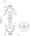
- a dynamic characteristic measurement device will be described with reference to Figs. 1 to 3 . It should be noted that a system configuration of the dynamic characteristic measurement device and a flow of dynamic characteristic measurement of a rotor will be described in detail in the description of a third embodiment to be described later. Herein, a configuration of a built-in gear type centrifugal compressor serving as one example of a dynamic characteristic measurement object, arrangement of magnetic force generators forming the dynamic characteristic measurement device, and oscillation modes by the magnetic force generators will be described.
- a built-in gear type centrifugal compressor 100 includes a rotor 6 having a rotation shaft 3, and impellers 4, 5 respectively attached to both ends of the rotation shaft 3. That is, the rotor 6 is formed by the rotation shaft 3 and the impellers 4, 5.
- a gear 7 (pinion gear) is provided in the rotation shaft 3 between the two impellers 4, 5. This gear 7 is meshed with a large gear (not shown) having a larger diameter than the gear 7, and the rotor 6 is rotated via the gear 7.
- a speed increasing mechanism is formed by the gear 7 and the large gear, and rotation speed of the rotor 6 is for example 20,000 to 30,000 rpm.
- Bearings 8 supporting the rotation shaft 3 are installed between the two impellers 4, 5 and on both sides of the gear 7.
- a seal 9 preventing leakage of a compressed gas is installed between the bearing 8 and the impeller 4 (5).
- the parts such as the rotor 6 are housed in a casing (not shown).
- One built-in gear type centrifugal compressor often includes a plurality of rotors 6 in which the gear 7, the bearings 8, the seals 9, and the like are incorporated.
- a built-in gear type centrifugal compressor including only one rotor 6 in which the gear 7, the bearings 8, the seals 9, and the like are incorporated may be used.
- the plurality of magnetic force generators (1a, 1b, 2a, 2b) is arranged on the back surface side of the impellers 4, 5 in such a manner that a rigid mode and a bending mode can be separately excited as a vibration mode of the rotor 6.
- the magnetic force generators (1a, 1b, 2a, 2b) are to oscillate the impeller 4 (5) with magnetic force. It should be noted that a flow of the compressed gas is shown by arrows in Fig. 1(a) .
- the back surface of the impeller 4 (5) indicates a surface of the impeller 4 (5) on the opposite side of a surface where the compressed gas flows.
- These magnetic force generators (1a, 1b, 2a, 2b) preferably change magnitude of the generated magnetic force by an electric signal.
- an electric magnet formed by winding a coil around an iron core or the like is suitable.
- the direction of the magnetic force generators (1a, 1b, 2a, 2b) is for example the direction parallel to the rotation shaft 3.
- the axial direction (longitudinal direction) of the iron core and the axial direction of the rotation shaft 3 are set to be parallel. It should be noted that these directions are not necessarily perfectly parallel.
- the axial direction (longitudinal direction) of the iron core is placed along the axial direction of the rotation shaft 3.
- the rotation shaft 3 and the impellers 4, 5 are orthogonal to each other.
- a material of the impellers 4, 5 is desirably a magnetic body on which magnetic attractive force acts, or a favorably conductive body in which an eddy current is generated.
- the magnetic body includes iron and stainless having a magnetic property.
- the favorably conductive body includes aluminum, an aluminum alloy, and copper.
- a magnetic member made of the magnetic body or a favorably conductive member made of the favorably conducive body may be attached to the back surfaces of the impellers 4, 5.
- Figs. 12(a)(b) One embodiment of this mode is shown in Figs. 12(a)(b) .
- plates 17 made of the magnetic body are attached to the back surfaces of the impellers 4, 5 by welding bonding or the like. It should be noted that thickness of the plates 17 is arbitrary. Although the plates 17 are attached to the entire back surfaces of the impellers 4, 5 in Figs.
- the plates 17 may be attached only to surfaces of the back surfaces of the impellers 4, 5, the surfaces that face the magnetic force generators (1a, 1b, 2a, 2b). Since the impellers 4, 5 are rotated, in this case, a shape of the plates 17 is a ring shape (annular shape).
- Fig. 1(a) is an AA arrow view of Fig. 1(a) .
- the magnetic force generators (1a, 2a) and the magnetic force generators (1b, 2b) arranged on both the sides of the rotation shaft 3 are arranged to face each other in the axial direction of the rotor 6.
- the magnetic force generator 1a and the magnetic force generator 2a are arranged on the substantially same straight line when seen from the axial direction of the rotor 6.
- the same is applied to the magnetic force generators (1b, 2b).
- the magnetic force generator 1b and the magnetic force generator 2b are arranged on the substantially same straight line when seen from the axial direction of the rotor 6.
- the magnetic force generators (1a, 1b, 2a, 2b) are preferably arranged at positions of the same distance from the shaft center of the rotation shaft 3. Further, the distance from the shaft center of the rotation shaft 3 is preferably as large as possible. That is, the magnetic force generators (1a, 1b, 2a, 2b) are preferably arranged in outermost peripheral parts (outer peripheral edges) of the impellers 4, 5 in the radial direction of the rotation shaft 3 (impellers 4, 5).
- the impellers 4, 5 have a shape of extending from the rotation shaft 3 outward in the radial direction of the impellers. Therefore, by oscillating the outermost peripheral parts of the impellers 4, 5 with the magnetic force from the magnetic force generators (1a, 1b, 2a, 2b), bending moment by the magnetic force can be more increased in comparison to oscillation of parts near the rotation shaft 3. As a result, a shaft vibration response is more increased, so that effective oscillation of the rotor 6 can be achieved.
- the rigid mode is a vibration mode coming first after starting vibration of the rotor 6, in which bending is small.
- the bending mode is a vibration mode coming next to the rigid mode after starting the vibration of the rotor 6, in which bending is relatively large.
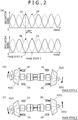
- Fig. 2(a) is a graph showing waveforms of oscillation signals to the magnetic force generators (1a, 1b, 2a, 2b) shown in Fig. 1(a) in a case where the rigid mode is excited. It should be noted that the oscillation signals are outputted from an oscillation signal generator 10 shown in Fig. 9 to be described later.
- a state of Fig. 2(b) and a state of Fig. 2(c) are a phase state A and a phase state B, respectively.
- the oscillation signal to each of the magnetic force generators (1a, 1b, 2a, 2b) corresponds, that is, whether the oscillation signal corresponds to the state of Fig. 2(b) or corresponds to the state of Fig. 2(c) is indicated by pointing with arrows in the waveform graph of Fig. 2(a) .
- Fig. 4(b) is an AA arrow view of Fig. 4(a) .
- magnetic force generators may also be arranged on the back surface side of an impeller 4 at a 90° interval in the rotation direction of the rotor 6.
- a phase of the oscillation signal to the other is displaced forward or backward by 90°. From this, the forward rotation mode and the backward rotation mode can be effectively excited.
- a dynamic characteristic measurement device according to the third embodiment of the present invention will be described with reference to Figs. 7 , 8 . It should be noted that description of the same configurations as the first embodiment will be omitted.
- a plurality of magnetic force generators (1a to 1d, 2a to 2d) is arranged on the back surface side of impellers 4, 5 in such a manner that a backward-rotation rigid mode, a forward-rotation rigid mode, a backward-rotation bending mode, and a forward-rotation bending mode are further separately excited as a vibration mode of a rotor 6.
- a phase difference between the oscillation signals to the pairs of the magnetic force generators arranged to face each other in the axial direction of the rotor 6, that is, the magnetic force generators 1a and 2a, the magnetic force generators 1b and 2b, the magnetic force generators 1c and 2c, and the magnetic force generators 1d and 2d is reversed (or the same phase). From this, the rigid mode (or the bending mode) can be effectively excited. By combining these, the backward-rotation rigid mode, the forward-rotation rigid mode, the backward-rotation bending mode, and the forward-rotation bending mode can be excited.
- Fig. 9 is a system configuration diagram of the dynamic characteristic measurement device including the magnetic force generators (1a to 1d, 2a to 2d) shown in Fig. 7(a) . It should be noted that a configuration of the magnetic force generators (1a to 1d) is the same as a configuration of the magnetic force generators (2a to 2d) in terms that the magnetic force generators are driven by a signal from the oscillation signal generator 10 (oscillation controller 12). Thus, the magnetic force generators (1a to 1d) are not shown in the figure.
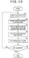
- Fig. 10 is a flowchart to measure a dynamic characteristic of the rotor 6 by the dynamic characteristic measurement device.
- the dynamic characteristic measurement device includes the magnetic force generators (1a to 1d, 2a to 2d), the oscillation controller 12 that drives these magnetic force generators (1a to 1d, 2a to 2d), vibration sensors (13, 14) that detect vibration of the rotation shaft 3, and an arithmetic device 16.
- the arithmetic device 16 calculates the dynamic characteristic of the rotor 6 by implementing a frequency analysis and a mode analysis based on the oscillation signals from the oscillation signal generator 10 (oscillation controller 12) and vibration signals (detection signals) from the vibration sensors (13, 14).
- the oscillation controller 12 is formed by the oscillation signal generator 10 and an amplifier 11.
- the oscillation signals from the oscillation signal generator 10 are also inputted to a signal meter 15.
- the vibration signals (vibration response signals) detected by the vibration sensors (13, 14) are taken into the signal meter 15. These signals are sent to the arithmetic device 16.
- the arithmetic device 16 calculates a transfer function from the oscillation signal to the vibration response by implementing the frequency analysis of oscillation signal data from the oscillation signal generator 10 and vibration response signal data from the vibration sensors (13, 14) (S3).
- the ERA method Eigensystem Realization Algorism
- a mode analysis method to the calculated transfer function G(f) by the arithmetic device 16 by the arithmetic device 16, a natural frequency, a damping ratio, and a vibration mode are determined (S4).
- the damping ratio is one example of the dynamic characteristic of the rotor 6.
- the calculated damping ratios of the vibration modes are plotted in a graph (S5). After that, from the calculated damping ratios of the vibration modes, rotation stability of the rotor 6 (shaft system) is evaluated. As an evaluation method of the rotation stability, for example by a graph in which the horizontal axis indicates gas power and the vertical axis indicates the damping ratio, a change in the damping ratio relative to a compressor load can be evaluated ( Fig. 11(a) ).
- the centrifugal rotation machine including the rotor 6 in which the impellers are attached to the shaft ends of the rotation shaft 3 is the dynamic characteristic measurement object for evaluating the rotation stability of the shaft system
- the dynamic characteristic of the rotor 6 can be measured with high precision while ensuring the fluid flow passage of the ends of the rotation shaft 3. It should be noted that thereby, the rotation stability of the centrifugal rotation machine can be evaluated with high precision.
- the dynamic characteristic of the rotor 6 in various vibration modes can be measured.
- the magnetic force generators 1a, 1b (2a, 2b) are arranged on the back surface side of the impeller 4 (5) at a 180° interval in the rotation direction of the rotor 6, and the magnetic force generators (1a and 2a, 1b and 2b) arranged on both the sides of the rotation shaft 3 are arranged to face each other in the axial direction of the rotor 6. Thereby, the rigid mode and the bending mode can be effectively excited as the vibration mode of the rotor 6.
- the magnetic force generators 1a, 1b are arranged on the back surface side of one impeller 5 at 90° interval in the rotation direction of the rotor 6. Thereby, the backward rotation mode and the forward rotation mode can be effectively excited.
- the two magnetic force generators 1a, 1b are displaced by a gap (phase difference) other than the gap of 180° in the rotation direction of the rotor 6 and arranged on the back surface side of the impeller. Thereby, the backward rotation mode and the forward rotation mode can be separately excited.
- the four magnetic force generators (1a to 1d, 2a to 2d) are arranged on the back surface side of each of the impellers 4, 5 at 90° interval in the rotation direction of the rotor 6. Further, the magnetic force generators (1a and 2a, 1b and 2b, 1c and 2c, 1d and 2d) arranged on both the sides of the rotation shaft 3 are all arranged to face each other in the axial direction of the rotor 6. From this, the total of four vibration modes including the backward-rotation rigid mode, the forward-rotation rigid mode, the backward-rotation bending mode, and the forward-rotation bending mode can be respectively separately excited.
- the present invention can be grasped as a centrifugal rotation machine including the dynamic characteristic measurement device as described above, a rotor in which impellers are attached to shaft ends of a rotation shaft, and the like.
Landscapes
- Engineering & Computer Science (AREA)
- Physics & Mathematics (AREA)
- Mechanical Engineering (AREA)
- General Engineering & Computer Science (AREA)
- General Physics & Mathematics (AREA)
- Electromagnetism (AREA)
- Power Engineering (AREA)
- Structures Of Non-Positive Displacement Pumps (AREA)
- Measurement Of Mechanical Vibrations Or Ultrasonic Waves (AREA)
- Testing Of Devices, Machine Parts, Or Other Structures Thereof (AREA)
Claims (10)
- Dispositif de mesure de caractéristiques dynamiques pour une machine rotative centrifuge comprenant un rotor (6) dans lequel un impulseur (4, 5) est fixé à une extrémité d'arbre d'un arbre de rotation (3), le dispositif de mesure de caractéristiques dynamiques comprenant :un générateur de force magnétique (1a-1d, 2a-2d) ;un organe de commande d'oscillation (12) configuré pour entraîner ledit générateur de force magnétique (1a-1d, 2a-2d) ;un capteur de vibration (13, 14) configuré pour détecter la vibration de l'arbre de rotation (3) ; etun dispositif arithmétique (16) configuré pour calculer une caractéristique dynamique du rotor en mettant en oeuvre une analyse de fréquence et une analyse de mode en fonction d'un signal d'oscillation provenant dudit organe de commande d'oscillation et d'un signal de vibration provenant dudit capteur de vibration,caractérisé en ce que :le générateur de force magnétique (1a-1d, 2a-2d) est configuré pour être agencé sur le côté de surface arrière de l'impulseur (4, 5), le générateur de force magnétique (1a-1d, 2a-2d) étant configuré pour faire osciller l'impulseur (4, 5) avec la force magnétique.
- Dispositif de mesure de caractéristiques dynamiques pour une machine rotative centrifuge selon la revendication 1,
dans lequel ledit générateur de force magnétique (1a-1d, 2a-2d) est configuré pour être agencé dans une partie périphérique située le plus à l'extérieur de l'impulseur (4, 5) dans la direction radiale de l'impulseur (4, 5). - Dispositif de mesure de caractéristiques dynamiques pour une machine rotative centrifuge selon la revendication 1, comprenant :un élément magnétique ou un élément favorablement conducteur configuré pour être fixé sur une surface arrière de l'impulseur (4, 5).
- Dispositif de mesure de caractéristiques dynamiques pour une machine rotative centrifuge selon la revendication 1,
dans lequel une pluralité de générateurs de force magnétique (1a-1d, 2a-2d) est configurée pour être agencée de sorte qu'un mode rigide et un mode de flexion peuvent être séparément excités en tant que mode de vibration du rotor (6). - Dispositif de mesure de caractéristiques dynamiques pour une machine rotative centrifuge selon la revendication 4,
dans lequel les impulseurs (4, 5) sont respectivement fixés aux deux extrémités de l'arbre de rotation (3) de la machine rotative centrifuge,
dans lequel lesdits générateurs de force magnétique (1a-1d, 2a-2d) sont configurés pour être agencés du côté de la surface arrière de chacun des impulseurs (4, 5) à un intervalle de 180° dans le sens de la rotation du rotor (6), et
dans lequel lesdits générateurs de force magnétique (1a-1d, 2a-2d) configurés pour être agencés des deux côtés de l'arbre de rotation sont configurés pour être agencés pour se faire face dans la direction axiale du rotor (6). - Dispositif de mesure de caractéristiques dynamiques pour une machine rotative centrifuge selon la revendication 1,
dans lequel une pluralité de générateurs de force magnétique (1a-1d, 2a-2d) est configurée pour être agencée de sorte qu'un mode de rotation en arrière et un mode de rotation en avant peuvent être excités séparément en tant que mode de vibration du rotor (6). - Dispositif de mesure de caractéristiques dynamiques pour une machine rotative centrifuge selon la revendication 6,
dans lequel lesdits générateurs de force magnétique (1a-1d, 2a-2d) sont configurés pour être agencés du côté de la surface arrière de l'impulseur à un intervalle de 90° dans le sens de rotation du rotor (6). - Dispositif de mesure de caractéristiques dynamiques pour une machine rotative centrifuge selon la revendication 1,
dans lequel une pluralité de générateurs de force magnétique (1a-1d, 2a-2d) est configurée pour être agencée de sorte qu'un mode rigide de rotation en arrière, un mode rigide de rotation en avant, un mode de flexion de rotation en arrière et un mode de flexion de rotation en avant peuvent être excités séparément en tant que mode de vibration du rotor (6). - Dispositif de mesure de caractéristiques dynamiques pour une machine rotative centrifuge selon la revendication 8,
dans lequel les impulseurs (4, 5) sont respectivement fixés aux deux extrémités de l'arbre de rotation (3) de la machine rotative centrifuge,
dans lequel quatre générateurs de force magnétiques (1a-1d, 2a-2d) sont configurés pour être agencés du côté de la surface arrière de chacun des impulseurs (4, 5) à un intervalle de 90° dans le sens de rotation du rotor (6), et
dans lequel lesdits générateurs de force magnétique (1a, 1d, 2a-2d) configurés pour être agencés des deux côtés de l'arbre de rotation (3) sont configurés pour être agencés afin de se faire face dans la direction axiale du rotor (6). - Machine rotative centrifuge comprenant :un dispositif de mesure de caractéristiques dynamiques de la machine rotative centrifuge selon la revendication 1 ; etun rotor (6) dans lequel un impulseur (4, 5) est fixé sur une extrémité d'arbre d'un arbre de rotation (3).
Applications Claiming Priority (2)
| Application Number | Priority Date | Filing Date | Title |
|---|---|---|---|
| JP2012253257A JP5937954B2 (ja) | 2012-11-19 | 2012-11-19 | 遠心式回転機械の動特性測定装置、および遠心式回転機械。 |
| PCT/JP2013/080676 WO2014077275A1 (fr) | 2012-11-19 | 2013-11-13 | Dispositif de mesure de caractéristiques dynamiques pour machine rotative centrifuge, et machine rotative centrifuge |
Publications (3)
| Publication Number | Publication Date |
|---|---|
| EP2921829A1 EP2921829A1 (fr) | 2015-09-23 |
| EP2921829A4 EP2921829A4 (fr) | 2016-07-13 |
| EP2921829B1 true EP2921829B1 (fr) | 2017-09-20 |
Family
ID=50731186
Family Applications (1)
| Application Number | Title | Priority Date | Filing Date |
|---|---|---|---|
| EP13855612.1A Not-in-force EP2921829B1 (fr) | 2012-11-19 | 2013-11-13 | Dispositif de mesure de caractéristiques dynamiques pour machine rotative centrifuge, et machine rotative centrifuge |
Country Status (4)
| Country | Link |
|---|---|
| US (2) | US9964435B2 (fr) |
| EP (1) | EP2921829B1 (fr) |
| JP (1) | JP5937954B2 (fr) |
| WO (1) | WO2014077275A1 (fr) |
Families Citing this family (22)
| Publication number | Priority date | Publication date | Assignee | Title |
|---|---|---|---|---|
| EP2980543A1 (fr) | 2014-07-28 | 2016-02-03 | ALSTOM Renewable Technologies | Dispositif et procédé pour mesurer les vibrations d'un rotor |
| CN104929944B (zh) * | 2015-06-09 | 2017-04-12 | 江苏大学 | 基于间隙流的多级泵转子动力密封的设计方法 |
| JP6475115B2 (ja) * | 2015-07-13 | 2019-02-27 | 株式会社神戸製鋼所 | 遠心式回転機械の動特性測定装置 |
| JP6473055B2 (ja) * | 2015-07-13 | 2019-02-20 | 株式会社神戸製鋼所 | 遠心式回転機械の動特性測定装置 |
| IL240316B (en) * | 2015-08-03 | 2018-10-31 | Technion Res & Dev Foundation | Method and system for parametric amplification |
| JP6577799B2 (ja) * | 2015-09-14 | 2019-09-18 | 株式会社神戸製鋼所 | 遠心式回転機械の動特性測定装置 |
| US10823643B2 (en) | 2015-11-06 | 2020-11-03 | Aktiebolaget Skf | Method and device for handling dynamic characteristics of a vibrating machine component |
| CN105675213A (zh) * | 2016-01-05 | 2016-06-15 | 国网甘肃省电力公司电力科学研究院 | 一种水轮发电机转子动平衡试验配重方法 |
| JP6524011B2 (ja) * | 2016-03-25 | 2019-06-05 | 株式会社日立製作所 | 加振診断装置及び加振診断方法 |
| JP6964971B2 (ja) | 2016-05-20 | 2021-11-10 | 株式会社神戸製鋼所 | 磁心 |
| CN105952688B (zh) * | 2016-06-06 | 2019-04-09 | 合肥通用机械研究院有限公司 | 一种离心叶轮受迫振动抑制系统及其控制方法 |
| CN106762708B (zh) * | 2016-11-18 | 2018-04-03 | 江苏大学 | 一种泵用轴向力最大值测量装置及测量方法 |
| CN108414080A (zh) * | 2018-06-11 | 2018-08-17 | 河北冀研能源科学技术研究院有限公司 | 用于在线测量汽轮发电机组转子轴径绝对振动的装置 |
| CN109870259B (zh) * | 2019-02-14 | 2021-02-09 | 五邑大学 | 盾构螺旋输送机与改性渣土间等效剪切应力测定装置 |
| CN111152937B (zh) * | 2020-01-20 | 2024-04-19 | 中国工程物理研究院总体工程研究所 | 离心场中振动台动圈定中装置及定中方法 |
| CN111473859B (zh) * | 2020-05-21 | 2022-07-29 | 中国航发湖南动力机械研究所 | 整机振动限制值的制定方法 |
| CN111947924B (zh) * | 2020-07-31 | 2022-05-27 | 南京航空航天大学 | 一种用于高速电主轴力学参数测试的电磁加载装置及方法 |
| CN111780938B (zh) * | 2020-08-21 | 2022-03-08 | 中国工程物理研究院总体工程研究所 | 一种离心机三向振动台 |
| CN114580102A (zh) * | 2022-02-24 | 2022-06-03 | 五邑大学 | 盾构机螺旋结构的驱动扭矩计算方法、装置及存储介质 |
| GB202302991D0 (en) * | 2023-03-01 | 2023-04-12 | Rolls Royce Plc | Excitation system |
| EP4425139A1 (fr) * | 2023-03-01 | 2024-09-04 | Rolls-Royce plc | Procédé d'analyse d'un système d'excitation |
| CN120522619B (zh) * | 2025-07-24 | 2025-10-03 | 山东天瑞重工有限公司 | 一种径向磁轴承测试装置 |
Family Cites Families (10)
| Publication number | Priority date | Publication date | Assignee | Title |
|---|---|---|---|---|
| JPS55147329A (en) * | 1979-05-04 | 1980-11-17 | Hitachi Ltd | Vibrator for impeller |
| JPH03160194A (ja) | 1989-11-15 | 1991-07-10 | Kenji Oe | ファン |
| JP3174676B2 (ja) * | 1993-10-29 | 2001-06-11 | 三菱重工業株式会社 | 翼振動回転試験用励振装置 |
| JPH08145058A (ja) | 1994-11-21 | 1996-06-04 | Hitachi Ltd | ロータの支持方法、カップリング装置、ラジアル磁気軸受、および回転式流体機械 |
| JP3083242B2 (ja) * | 1995-04-27 | 2000-09-04 | 核燃料サイクル開発機構 | 回転体の静止場での振動評価方法 |
| JP2001173590A (ja) | 1999-12-15 | 2001-06-26 | Hitachi Ltd | ターボ形遠心圧縮機 |
| JP4324734B2 (ja) * | 2004-02-17 | 2009-09-02 | 株式会社島津製作所 | 磁気軸受制御装置 |
| JP2008190328A (ja) * | 2007-01-31 | 2008-08-21 | Jtekt Corp | 遠心式圧縮機 |
| JP2012082803A (ja) * | 2010-10-14 | 2012-04-26 | Hitachi Plant Technologies Ltd | 遠心圧縮機およびその運転監視方法 |
| JP2012172756A (ja) * | 2011-02-21 | 2012-09-10 | Mitsubishi Heavy Ind Ltd | 磁気軸受装置、および回転機械 |
-
2012
- 2012-11-19 JP JP2012253257A patent/JP5937954B2/ja active Active
-
2013
- 2013-11-13 US US14/434,950 patent/US9964435B2/en active Active
- 2013-11-13 WO PCT/JP2013/080676 patent/WO2014077275A1/fr not_active Ceased
- 2013-11-13 EP EP13855612.1A patent/EP2921829B1/fr not_active Not-in-force
-
2018
- 2018-03-30 US US15/942,133 patent/US10677644B2/en not_active Expired - Fee Related
Non-Patent Citations (1)
| Title |
|---|
| None * |
Also Published As
| Publication number | Publication date |
|---|---|
| EP2921829A4 (fr) | 2016-07-13 |
| US9964435B2 (en) | 2018-05-08 |
| US10677644B2 (en) | 2020-06-09 |
| EP2921829A1 (fr) | 2015-09-23 |
| US20150285672A1 (en) | 2015-10-08 |
| JP2014102117A (ja) | 2014-06-05 |
| JP5937954B2 (ja) | 2016-06-22 |
| US20180274971A1 (en) | 2018-09-27 |
| WO2014077275A1 (fr) | 2014-05-22 |
Similar Documents
| Publication | Publication Date | Title |
|---|---|---|
| EP2921829B1 (fr) | Dispositif de mesure de caractéristiques dynamiques pour machine rotative centrifuge, et machine rotative centrifuge | |
| JP6122237B2 (ja) | ロータダイナミックシステムの横振動、角振動およびねじり振動監視 | |
| CA2662034C (fr) | Detection des felures dans les rotors a aimant permanent | |
| US11959978B2 (en) | Method of detecting a rotor bar fault and a method of estimating an additional operating expenditure due to one or more mechanical anomalies in an electrical machine | |
| Tomassini et al. | On the development of a magnetoresistive sensor for blade tip timing and blade tip clearance measurement systems | |
| EP3351911B1 (fr) | Dispositif de mesure de caractéristiques dynamiques de machine rotative centrifuge | |
| JP2011182639A (ja) | 電気機械における磁気素子の振動モニタリング | |
| JP2016075481A (ja) | 軸受装置およびこれを備える回転機械 | |
| Meroño et al. | Measurement techniques of torsional vibration in rotating shafts | |
| CN105934657A (zh) | 涡轮发动机的用于测量旋转叶片所承受的振动的组件 | |
| JP2002071532A (ja) | 機械要素の反力測定装置 | |
| JP3756531B2 (ja) | 水力機械 | |
| CN207610853U (zh) | 旋转机械偏摆量的测量装置 | |
| JP6524011B2 (ja) | 加振診断装置及び加振診断方法 | |
| Goel et al. | Exploring the potential of smartphone MEMS sensors for cost-effective rotating machinery speed estimation | |
| Luo et al. | Keyphasor® based torsional vibration detection and field applications | |
| CN109765051A (zh) | 旋转机械偏摆量的测量装置及测量方法 | |
| RU2131598C1 (ru) | Устройство для контроля целостности лопаток ротора турбины | |
| US20250093377A1 (en) | Hybrid rotational speed detector | |
| Arif et al. | Measurement of machine vibrations by using a fast rotating magnetic field | |
| JP2016090414A (ja) | 回転機械の軸軌跡表示装置 | |
| Chatterjee | Get the Most out of Vibration Analysis. | |
| Kiani et al. | Detection of faults in PMSM using field reconstruction method and mechanical impulse response | |
| JP2022066735A (ja) | タービンロータの曲がり検出装置及びタービンロータの曲がり検出方法 | |
| Meroño Pérez et al. | Measurement techniques of torsional vibration in rotating shafts |
Legal Events
| Date | Code | Title | Description |
|---|---|---|---|
| PUAI | Public reference made under article 153(3) epc to a published international application that has entered the european phase |
Free format text: ORIGINAL CODE: 0009012 |
|
| 17P | Request for examination filed |
Effective date: 20150414 |
|
| AK | Designated contracting states |
Kind code of ref document: A1 Designated state(s): AL AT BE BG CH CY CZ DE DK EE ES FI FR GB GR HR HU IE IS IT LI LT LU LV MC MK MT NL NO PL PT RO RS SE SI SK SM TR |
|
| AX | Request for extension of the european patent |
Extension state: BA ME |
|
| DAX | Request for extension of the european patent (deleted) | ||
| RIC1 | Information provided on ipc code assigned before grant |
Ipc: F04D 17/12 20060101ALI20160602BHEP Ipc: F04D 15/00 20060101ALI20160602BHEP Ipc: F04D 1/06 20060101AFI20160602BHEP Ipc: F04D 27/00 20060101ALI20160602BHEP Ipc: G01M 99/00 20110101ALI20160602BHEP Ipc: G01H 17/00 20060101ALI20160602BHEP |
|
| RA4 | Supplementary search report drawn up and despatched (corrected) |
Effective date: 20160609 |
|
| REG | Reference to a national code |
Ref country code: DE Ref legal event code: R079 Ref document number: 602013026981 Country of ref document: DE Free format text: PREVIOUS MAIN CLASS: G01H0017000000 Ipc: F04D0001060000 |
|
| GRAP | Despatch of communication of intention to grant a patent |
Free format text: ORIGINAL CODE: EPIDOSNIGR1 |
|
| RIC1 | Information provided on ipc code assigned before grant |
Ipc: F04D 1/00 20060101ALI20170316BHEP Ipc: F04D 17/10 20060101ALI20170316BHEP Ipc: H01F 7/20 20060101ALI20170316BHEP Ipc: G01H 1/00 20060101ALI20170316BHEP Ipc: H01F 7/06 20060101ALI20170316BHEP Ipc: F04D 1/06 20060101AFI20170316BHEP Ipc: G01M 7/04 20060101ALI20170316BHEP Ipc: G01M 1/22 20060101ALI20170316BHEP Ipc: F04D 29/66 20060101ALI20170316BHEP Ipc: F04D 27/00 20060101ALI20170316BHEP Ipc: F04D 15/00 20060101ALI20170316BHEP |
|
| INTG | Intention to grant announced |
Effective date: 20170405 |
|
| GRAS | Grant fee paid |
Free format text: ORIGINAL CODE: EPIDOSNIGR3 |
|
| GRAA | (expected) grant |
Free format text: ORIGINAL CODE: 0009210 |
|
| AK | Designated contracting states |
Kind code of ref document: B1 Designated state(s): AL AT BE BG CH CY CZ DE DK EE ES FI FR GB GR HR HU IE IS IT LI LT LU LV MC MK MT NL NO PL PT RO RS SE SI SK SM TR |
|
| REG | Reference to a national code |
Ref country code: GB Ref legal event code: FG4D |
|
| REG | Reference to a national code |
Ref country code: CH Ref legal event code: EP |
|
| REG | Reference to a national code |
Ref country code: AT Ref legal event code: REF Ref document number: 930384 Country of ref document: AT Kind code of ref document: T Effective date: 20171015 |
|
| REG | Reference to a national code |
Ref country code: IE Ref legal event code: FG4D |
|
| REG | Reference to a national code |
Ref country code: DE Ref legal event code: R096 Ref document number: 602013026981 Country of ref document: DE |
|
| REG | Reference to a national code |
Ref country code: NL Ref legal event code: MP Effective date: 20170920 |
|
| PG25 | Lapsed in a contracting state [announced via postgrant information from national office to epo] |
Ref country code: HR Free format text: LAPSE BECAUSE OF FAILURE TO SUBMIT A TRANSLATION OF THE DESCRIPTION OR TO PAY THE FEE WITHIN THE PRESCRIBED TIME-LIMIT Effective date: 20170920 Ref country code: LT Free format text: LAPSE BECAUSE OF FAILURE TO SUBMIT A TRANSLATION OF THE DESCRIPTION OR TO PAY THE FEE WITHIN THE PRESCRIBED TIME-LIMIT Effective date: 20170920 Ref country code: FI Free format text: LAPSE BECAUSE OF FAILURE TO SUBMIT A TRANSLATION OF THE DESCRIPTION OR TO PAY THE FEE WITHIN THE PRESCRIBED TIME-LIMIT Effective date: 20170920 Ref country code: NO Free format text: LAPSE BECAUSE OF FAILURE TO SUBMIT A TRANSLATION OF THE DESCRIPTION OR TO PAY THE FEE WITHIN THE PRESCRIBED TIME-LIMIT Effective date: 20171220 Ref country code: SE Free format text: LAPSE BECAUSE OF FAILURE TO SUBMIT A TRANSLATION OF THE DESCRIPTION OR TO PAY THE FEE WITHIN THE PRESCRIBED TIME-LIMIT Effective date: 20170920 |
|
| REG | Reference to a national code |
Ref country code: LT Ref legal event code: MG4D |
|
| REG | Reference to a national code |
Ref country code: AT Ref legal event code: MK05 Ref document number: 930384 Country of ref document: AT Kind code of ref document: T Effective date: 20170920 |
|
| PG25 | Lapsed in a contracting state [announced via postgrant information from national office to epo] |
Ref country code: LV Free format text: LAPSE BECAUSE OF FAILURE TO SUBMIT A TRANSLATION OF THE DESCRIPTION OR TO PAY THE FEE WITHIN THE PRESCRIBED TIME-LIMIT Effective date: 20170920 Ref country code: GR Free format text: LAPSE BECAUSE OF FAILURE TO SUBMIT A TRANSLATION OF THE DESCRIPTION OR TO PAY THE FEE WITHIN THE PRESCRIBED TIME-LIMIT Effective date: 20171221 Ref country code: BG Free format text: LAPSE BECAUSE OF FAILURE TO SUBMIT A TRANSLATION OF THE DESCRIPTION OR TO PAY THE FEE WITHIN THE PRESCRIBED TIME-LIMIT Effective date: 20171220 Ref country code: RS Free format text: LAPSE BECAUSE OF FAILURE TO SUBMIT A TRANSLATION OF THE DESCRIPTION OR TO PAY THE FEE WITHIN THE PRESCRIBED TIME-LIMIT Effective date: 20170920 |
|
| PG25 | Lapsed in a contracting state [announced via postgrant information from national office to epo] |
Ref country code: NL Free format text: LAPSE BECAUSE OF FAILURE TO SUBMIT A TRANSLATION OF THE DESCRIPTION OR TO PAY THE FEE WITHIN THE PRESCRIBED TIME-LIMIT Effective date: 20170920 |
|
| PG25 | Lapsed in a contracting state [announced via postgrant information from national office to epo] |
Ref country code: RO Free format text: LAPSE BECAUSE OF FAILURE TO SUBMIT A TRANSLATION OF THE DESCRIPTION OR TO PAY THE FEE WITHIN THE PRESCRIBED TIME-LIMIT Effective date: 20170920 Ref country code: CZ Free format text: LAPSE BECAUSE OF FAILURE TO SUBMIT A TRANSLATION OF THE DESCRIPTION OR TO PAY THE FEE WITHIN THE PRESCRIBED TIME-LIMIT Effective date: 20170920 Ref country code: ES Free format text: LAPSE BECAUSE OF FAILURE TO SUBMIT A TRANSLATION OF THE DESCRIPTION OR TO PAY THE FEE WITHIN THE PRESCRIBED TIME-LIMIT Effective date: 20170920 Ref country code: PL Free format text: LAPSE BECAUSE OF FAILURE TO SUBMIT A TRANSLATION OF THE DESCRIPTION OR TO PAY THE FEE WITHIN THE PRESCRIBED TIME-LIMIT Effective date: 20170920 |
|
| PG25 | Lapsed in a contracting state [announced via postgrant information from national office to epo] |
Ref country code: SM Free format text: LAPSE BECAUSE OF FAILURE TO SUBMIT A TRANSLATION OF THE DESCRIPTION OR TO PAY THE FEE WITHIN THE PRESCRIBED TIME-LIMIT Effective date: 20170920 Ref country code: SK Free format text: LAPSE BECAUSE OF FAILURE TO SUBMIT A TRANSLATION OF THE DESCRIPTION OR TO PAY THE FEE WITHIN THE PRESCRIBED TIME-LIMIT Effective date: 20170920 Ref country code: IT Free format text: LAPSE BECAUSE OF FAILURE TO SUBMIT A TRANSLATION OF THE DESCRIPTION OR TO PAY THE FEE WITHIN THE PRESCRIBED TIME-LIMIT Effective date: 20170920 Ref country code: EE Free format text: LAPSE BECAUSE OF FAILURE TO SUBMIT A TRANSLATION OF THE DESCRIPTION OR TO PAY THE FEE WITHIN THE PRESCRIBED TIME-LIMIT Effective date: 20170920 Ref country code: IS Free format text: LAPSE BECAUSE OF FAILURE TO SUBMIT A TRANSLATION OF THE DESCRIPTION OR TO PAY THE FEE WITHIN THE PRESCRIBED TIME-LIMIT Effective date: 20180120 Ref country code: AT Free format text: LAPSE BECAUSE OF FAILURE TO SUBMIT A TRANSLATION OF THE DESCRIPTION OR TO PAY THE FEE WITHIN THE PRESCRIBED TIME-LIMIT Effective date: 20170920 |
|
| REG | Reference to a national code |
Ref country code: DE Ref legal event code: R097 Ref document number: 602013026981 Country of ref document: DE |
|
| PG25 | Lapsed in a contracting state [announced via postgrant information from national office to epo] |
Ref country code: MC Free format text: LAPSE BECAUSE OF FAILURE TO SUBMIT A TRANSLATION OF THE DESCRIPTION OR TO PAY THE FEE WITHIN THE PRESCRIBED TIME-LIMIT Effective date: 20170920 |
|
| PLBE | No opposition filed within time limit |
Free format text: ORIGINAL CODE: 0009261 |
|
| STAA | Information on the status of an ep patent application or granted ep patent |
Free format text: STATUS: NO OPPOSITION FILED WITHIN TIME LIMIT |
|
| PG25 | Lapsed in a contracting state [announced via postgrant information from national office to epo] |
Ref country code: DK Free format text: LAPSE BECAUSE OF FAILURE TO SUBMIT A TRANSLATION OF THE DESCRIPTION OR TO PAY THE FEE WITHIN THE PRESCRIBED TIME-LIMIT Effective date: 20170920 Ref country code: LI Free format text: LAPSE BECAUSE OF NON-PAYMENT OF DUE FEES Effective date: 20171130 Ref country code: CH Free format text: LAPSE BECAUSE OF NON-PAYMENT OF DUE FEES Effective date: 20171130 |
|
| 26N | No opposition filed |
Effective date: 20180621 |
|
| GBPC | Gb: european patent ceased through non-payment of renewal fee |
Effective date: 20171220 |
|
| PG25 | Lapsed in a contracting state [announced via postgrant information from national office to epo] |
Ref country code: LU Free format text: LAPSE BECAUSE OF NON-PAYMENT OF DUE FEES Effective date: 20171113 |
|
| REG | Reference to a national code |
Ref country code: FR Ref legal event code: ST Effective date: 20180731 Ref country code: BE Ref legal event code: MM Effective date: 20171130 |
|
| REG | Reference to a national code |
Ref country code: IE Ref legal event code: MM4A |
|
| PG25 | Lapsed in a contracting state [announced via postgrant information from national office to epo] |
Ref country code: MT Free format text: LAPSE BECAUSE OF NON-PAYMENT OF DUE FEES Effective date: 20171113 |
|
| PG25 | Lapsed in a contracting state [announced via postgrant information from national office to epo] |
Ref country code: IE Free format text: LAPSE BECAUSE OF NON-PAYMENT OF DUE FEES Effective date: 20171113 Ref country code: FR Free format text: LAPSE BECAUSE OF NON-PAYMENT OF DUE FEES Effective date: 20171130 |
|
| PG25 | Lapsed in a contracting state [announced via postgrant information from national office to epo] |
Ref country code: BE Free format text: LAPSE BECAUSE OF NON-PAYMENT OF DUE FEES Effective date: 20171130 Ref country code: SI Free format text: LAPSE BECAUSE OF FAILURE TO SUBMIT A TRANSLATION OF THE DESCRIPTION OR TO PAY THE FEE WITHIN THE PRESCRIBED TIME-LIMIT Effective date: 20170920 Ref country code: GB Free format text: LAPSE BECAUSE OF NON-PAYMENT OF DUE FEES Effective date: 20171220 |
|
| PG25 | Lapsed in a contracting state [announced via postgrant information from national office to epo] |
Ref country code: HU Free format text: LAPSE BECAUSE OF FAILURE TO SUBMIT A TRANSLATION OF THE DESCRIPTION OR TO PAY THE FEE WITHIN THE PRESCRIBED TIME-LIMIT; INVALID AB INITIO Effective date: 20131113 |
|
| PG25 | Lapsed in a contracting state [announced via postgrant information from national office to epo] |
Ref country code: CY Free format text: LAPSE BECAUSE OF FAILURE TO SUBMIT A TRANSLATION OF THE DESCRIPTION OR TO PAY THE FEE WITHIN THE PRESCRIBED TIME-LIMIT Effective date: 20170920 |
|
| PG25 | Lapsed in a contracting state [announced via postgrant information from national office to epo] |
Ref country code: MK Free format text: LAPSE BECAUSE OF FAILURE TO SUBMIT A TRANSLATION OF THE DESCRIPTION OR TO PAY THE FEE WITHIN THE PRESCRIBED TIME-LIMIT Effective date: 20170920 |
|
| PG25 | Lapsed in a contracting state [announced via postgrant information from national office to epo] |
Ref country code: TR Free format text: LAPSE BECAUSE OF FAILURE TO SUBMIT A TRANSLATION OF THE DESCRIPTION OR TO PAY THE FEE WITHIN THE PRESCRIBED TIME-LIMIT Effective date: 20170920 |
|
| PG25 | Lapsed in a contracting state [announced via postgrant information from national office to epo] |
Ref country code: PT Free format text: LAPSE BECAUSE OF FAILURE TO SUBMIT A TRANSLATION OF THE DESCRIPTION OR TO PAY THE FEE WITHIN THE PRESCRIBED TIME-LIMIT Effective date: 20170920 |
|
| PG25 | Lapsed in a contracting state [announced via postgrant information from national office to epo] |
Ref country code: AL Free format text: LAPSE BECAUSE OF FAILURE TO SUBMIT A TRANSLATION OF THE DESCRIPTION OR TO PAY THE FEE WITHIN THE PRESCRIBED TIME-LIMIT Effective date: 20170920 |
|
| PGFP | Annual fee paid to national office [announced via postgrant information from national office to epo] |
Ref country code: DE Payment date: 20210923 Year of fee payment: 9 |
|
| REG | Reference to a national code |
Ref country code: DE Ref legal event code: R119 Ref document number: 602013026981 Country of ref document: DE |
|
| PG25 | Lapsed in a contracting state [announced via postgrant information from national office to epo] |
Ref country code: DE Free format text: LAPSE BECAUSE OF NON-PAYMENT OF DUE FEES Effective date: 20230601 |