EP2921864B1 - Stromsensor - Google Patents
Stromsensor Download PDFInfo
- Publication number
- EP2921864B1 EP2921864B1 EP14160246.6A EP14160246A EP2921864B1 EP 2921864 B1 EP2921864 B1 EP 2921864B1 EP 14160246 A EP14160246 A EP 14160246A EP 2921864 B1 EP2921864 B1 EP 2921864B1
- Authority
- EP
- European Patent Office
- Prior art keywords
- wire
- arms
- axis
- current
- current sensor
- Prior art date
- Legal status (The legal status is an assumption and is not a legal conclusion. Google has not performed a legal analysis and makes no representation as to the accuracy of the status listed.)
- Not-in-force
Links
- 238000006073 displacement reaction Methods 0.000 claims description 40
- 230000035945 sensitivity Effects 0.000 claims description 31
- 230000008859 change Effects 0.000 claims description 28
- 230000007246 mechanism Effects 0.000 claims description 7
- 238000004804 winding Methods 0.000 claims 1
- 230000008878 coupling Effects 0.000 description 31
- 238000010168 coupling process Methods 0.000 description 31
- 238000005859 coupling reaction Methods 0.000 description 31
- 230000004048 modification Effects 0.000 description 10
- 238000012986 modification Methods 0.000 description 10
- 239000000758 substrate Substances 0.000 description 10
- 239000004020 conductor Substances 0.000 description 8
- 238000006243 chemical reaction Methods 0.000 description 4
- 238000010586 diagram Methods 0.000 description 4
- 230000005355 Hall effect Effects 0.000 description 3
- 230000001154 acute effect Effects 0.000 description 3
- 238000004088 simulation Methods 0.000 description 3
- 239000007787 solid Substances 0.000 description 3
- 238000003780 insertion Methods 0.000 description 2
- 230000037431 insertion Effects 0.000 description 2
- 238000009434 installation Methods 0.000 description 2
- 238000005259 measurement Methods 0.000 description 2
- 230000001419 dependent effect Effects 0.000 description 1
- 230000000694 effects Effects 0.000 description 1
- 238000005516 engineering process Methods 0.000 description 1
- 230000004907 flux Effects 0.000 description 1
- 239000011810 insulating material Substances 0.000 description 1
- 239000000696 magnetic material Substances 0.000 description 1
- 239000006247 magnetic powder Substances 0.000 description 1
- 230000009467 reduction Effects 0.000 description 1
- 239000004065 semiconductor Substances 0.000 description 1
- 230000005641 tunneling Effects 0.000 description 1
Images





Classifications
-
- G—PHYSICS
- G01—MEASURING; TESTING
- G01R—MEASURING ELECTRIC VARIABLES; MEASURING MAGNETIC VARIABLES
- G01R15/00—Details of measuring arrangements of the types provided for in groups G01R17/00 - G01R29/00, G01R33/00 - G01R33/26 or G01R35/00
- G01R15/14—Adaptations providing voltage or current isolation, e.g. for high-voltage or high-current networks
- G01R15/20—Adaptations providing voltage or current isolation, e.g. for high-voltage or high-current networks using galvano-magnetic devices, e.g. Hall-effect devices, i.e. measuring a magnetic field via the interaction between a current and a magnetic field, e.g. magneto resistive or Hall effect devices
- G01R15/207—Constructional details independent of the type of device used
Definitions
- the present invention relates to current sensors for measuring target current flowing through an electric wire (hereinafter, referred to as a "wire"), and in particular, relates to a current sensor including a magnetic sensing element.
- Such current sensors Recently developed include a current sensor that allows magnetic sensor elements to detect a change in magnetic field caused by target current (refer to Japanese Unexamined Patent Application Publication No. 2006-322706 , for example).
- the current sensor disclosed in Japanese Unexamined Patent Application Publication No. 2006-322706 includes a substrate with a slit having a circular end located in middle part of the substrate and four magnetic impedance elements arranged apart so as to surround a wire extending through the circular end of the slit.
- a target current is determined on the basis of the sum of values of signals output from the magnetic impedance elements, the values varying depending on an induced magnetic field from the target current flowing through the wire extending through the circular end of the slit.
- the current sensor As an installation position of the current sensor is displaced relative to a wire, a magnetic flux density at the position of the sensor significantly changes. Accordingly, when the installation position of the current sensor including the magnetic impedance elements is displaced relative to the wire, the output of the sensor significantly fluctuates. The current sensor therefore has to be securely fixed to the wire.
- the current sensor disclosed in Japanese Unexamined Patent Application Publication No. 2006-322706 is positioned and fixed by pressing the wire against an inner surface of the circular end of the slit.
- WO 2013/128993 A1 discloses a current sensor comprising a first magnetoelectric conversion element group including magnetoelectric conversion elements, and a second magnetoelectric conversion element group including magnetoelectric conversion elements are arranged across a cutout of a wiring board.
- the first and second groups are arranged line-symmetrically with respect to a first imaginary line.
- the elements in the first and second groups are arranged line-symmetrically with respect to a second imaginary line.
- the first imaginary line and the second imaginary line orthogonally intersect each other at a placement position at which a current path to be measured is placed.
- the orientation of the sensitivity axis of each of a plurality of magnetoelectric-conversion-element sets having point symmetry about the placement position is parallel or antiparallel.
- An element spacing, which is spacing between neighboring elements in the first and second groups is narrower than a group spacing, which is the narrowest spacing between the first and second groups.
- a current sensor for non-invasively measuring electrical current in an electrical conductor.
- the current sensor includes a housing having a Hall effect device and circuitry for transmitting a signal indicative of the current flowing through the electrical conductor.
- the current sensor includes a base having a surface for supporting an electrical conductor.
- a magnetic shielding member is coupled to the surface to shield the Hall effect device from stray or external magnetic fields.
- a compliant member is coupled to the magnetic shielding member opposite the surface. The compliant member compresses to allow the current sensor to accommodate a large variety of electrical conductor sizes. The compliant member further acts to bias the electrical conductor against the Hall effect device.
- EP 0 072 422 A1 describes a magnetic core made of soft magnetic material for a current sensor, which surrounds an electrical conductor and in which there is provided a notch having a magnetic field-dependent semiconductor element arranged therein.
- the magnetic core consists of a soft magnetic powder, which is consolidated together with insulating material, and has an essentially U-shaped core member, the open side of which can be covered by an end piece after the insertion of the electrical conductor.
- the U-shaped core member has V-shaped stop faces at the interior against which the electrical conductor rests.
- the present invention provides a current sensor according to claim 1, capable of preventing a fluctuation in output caused by displacement of a wire depending on diameter and supporting various wire diameters.
- a current sensor includes a casing including a pair of arms and coupling part coupling the arms, multiple magneto-electric transducers accommodated in the casing, the magneto-electric transducers being arranged on the circumference of a virtual ellipse having a major axis and a minor axis, the major axis or the minor axis extending between the arms, a support disposed obliquely relative to the major axis or the minor axis extending between the arms so as to be close to one of the arms when viewed from the center of a wire disposed and fastened between the arms, and a band wound around a circumferential surface of the wire fastened between the arms, part of the band being caught by the support, the wire being fastened by the band such that the center of the wire is held close to the support.
- the support may support the wire such that the center of the wire is located in a line extending in a direction in which a change in sensitivity caused by displacement of the wire is relatively smaller than that caused by displacement of the wire in the direction along the major axis or the minor axis of the virtual ellipse.
- the center of the wire is located in the line extending in the direction in which the sensitivity of the current sensor is least likely to change. Consequently, a change in sensitivity can be reduced, thus improving the accuracy of measurement of target current flowing through the wire.
- the support may be disposed in a direction at 45° relative to the major axis or the minor axis of the virtual ellipse extending between the arms such that the support is close to one of the arms, the major axis or the minor axis being at 0°.
- a current sensor includes a casing including a pair of arms and coupling part coupling the arms, multiple magneto-electric transducers accommodated in the casing, the magneto-electric transducers being arranged on the circumference of a virtual ellipse having a major axis and a minor axis, the major axis or the minor axis extending between the arms, and a fastening member disposed between the arms, wherein the casing includes a first wire supporting portion disposed in an inner wall of one of the arms and a second wire supporting portion disposed in an inner wall of the coupling part, and wherein the fastening member has a bevel inclined from one of the arms to the other arm.
- the first wire supporting portion, the second wire supporting portion, and the bevel fasten a wire such that the center of the wire is located in a line extending in a direction in which a change in sensitivity caused by displacement of the wire is relatively smaller than that caused by displacement in the direction along the major axis or the minor axis of the virtual ellipse.
- the center of the wire is located in the line extending in the direction in which the sensitivity of the current sensor is least likely to change. Consequently, a change in sensitivity can be reduced, thus improving the accuracy of measurement of target current flowing through the wire.
- the first wire supporting portion, the second wire supporting portion, and the bevel are arranged in a direction at 45° relative to the direction along the major axis or the minor axis of the virtual ellipse extending between the arms such that the portions and the bevel are close to one of the arms, the major axis or the minor axis being at 0°.
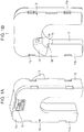
- Figs. 1A and 1B are perspective views of a current sensor according to the present embodiment.
- Fig. 2 is an exploded perspective view of the current sensor illustrated in Figs. 1A and 1B.
- Fig. 1A is a perspective view of the current sensor as viewed from a connector side (hereinafter, referred to as a first surface).
- Fig. 1B is a perspective view of the current sensor viewed from the opposite side (hereinafter, referred to as a second surface) of the current sensor from that illustrated in Fig. 1A .
- the current sensor, indicated at 1 includes a U-shaped casing that includes a pair of arms 11a and 11b extending in the same direction and coupling part 11c which corresponds to the base of the "U" shape and couples proximal ends of the arms 11a and 11b.
- the current sensor 1 has a first surface 1a in which a connector 12 for connection to a distribution cable is disposed near an upper end of the coupling part 11c of the casing (refer to Fig. 1A ), provided that distal ends of the arms 11a and 11b correspond to a lower end of the casing.
- the current sensor 1 has a second surface 1b on which a support 13 having a band hole 13a for wire fastening is disposed at the intersection between the arm 11b and the coupling part 11c (refer to Fig. 1B ). The position of the intersection at which the support 13 is disposed will be described later.
- the U-shaped casing of the current sensor 1 includes a casing portion 20 having a receiving space 20a corresponding to the U-shaped contour, a sensor substrate 30 disposed in the receiving space 20a of the casing portion 20, and a lid 40 that closes an opening (corresponding to the first surface 1a) of the receiving space 20a of the casing portion 20.
- the casing portion 20 includes an outer wall 21 defining the second surface 1b and a side wall 22 extending perpendicularly from an outer edge of the outer wall 21 by a distance corresponding to the thickness of the receiving space 20a.
- the receiving space 20a is defined by the outer wall 21 and the side wall 22 of the casing portion 20 and the lid 40.
- the support 13 is disposed on the outer wall 21 (the second surface 1b) of the casing portion 20.
- the outer wall 21 has a plurality of engagement holes 23a to 23d for attachment of the lid 40.
- the sensor substrate 30 is provided with a plurality of magneto-electric transducers 31 (31a to 31h) configured to output a signal based on an induced magnetic field around a wire through which target current flows.
- the sensor substrate 30 is further provided with the connector 12 through which output signals of the magneto-electric transducers 31 are taken to the outside of the sensor, the connector 12 being placed on upper end part of the sensor substrate 30.
- a distribution cord is connected to the connector 12, thus enabling the output signals based on target current flowing through the wire to be taken to the outside of the current sensor 1.
- the lid 40 includes an outer wall 41 defining the first surface 1a and a plurality of engagement lugs 42a and 42b (and engagement lugs 42c and 42d hidden by the outer wall 41) arranged so as to correspond to the engagement holes 23a to 23d of the casing portion 20, respectively.
- the lid 40 is attached and fixed to the casing portion 20 by inserting the engagement lugs 42a to 42d of the lid 40 into the engagement holes 23a to 23d arranged in the outer wall 21 of the casing portion 20, respectively.
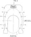
- Fig. 3 is a plan view of the sensor substrate 30.
- the sensor substrate 30 is U-shaped so as to correspond to the shape of the receiving space 20a in plan view such that the sensor substrate 30 can be fitted in the receiving space 20a of the casing portion 20.
- the sensor substrate 30 extends over an area corresponding to the arms 11a and 11b and the coupling part 11c of the current sensor 1.
- the magneto-electric transducers 31 are arranged in this area.
- eight magneto-electric transducers 31a to 31h are arranged on the circumference of a virtual ellipse E disposed over the arms 11a and 11b and the coupling part 11c.
- the major axis of the virtual ellipse E extends between the arms 11a and 11b.
- the magneto-electric transducers 31a to 31h are arranged on the circumference of the virtual ellipse E such that the major axis of the virtual ellipse E coincides with an intermediate line between the arms 11a and 11b.
- the position of the support 13 may be defined as follows. It is assumed that a wire is guided and fastened between the arms 11a and 11b, provided that the magneto-electric transducers 31a to 31h are arranged on the circumference of the virtual ellipse E and the major axis of the virtual ellipse E extends between the arms 11a and 11b. When viewed from the center of the wire fastened between the arms 11a and 11b, the support 13 is disposed obliquely relative to the major axis extending between the arms 11a and 11b so as to be close to the arm 11b.
- the support 13 is disposed obliquely relative to the minor axis extending between the arms 11a and 11b so as to be close to the arm 11b.
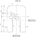
- the position of the support 13 may be defined as follows. As described above, the support 13 is disposed at the intersection between the arm 11b and the coupling part 11c on the outer wall 21 (the second surface 1b) of the current sensor 1. As illustrated in Fig. 4 , let D1 denote a range corresponding to the arm 11b and let D2 denote a range corresponding to the coupling part 11c in a direction (hereinafter, also referred to as the "major axis direction") along the major axis of the virtual ellipse E.
- the center of the intersection coincides with a point P of intersection between a line L1 extending along an inner wall of the arm 11b in the major axis direction and a line L2 extending along a lower surface of the coupling part 11c in a direction (hereinafter, also referred to as the "minor axis direction") along the minor axis of the virtual ellipse E.
- the arms 11a and 11b and the coupling part 11c can be defined such that a range D11 including the straight inner walls 14 and 15 corresponds to the arms 11a and 11b and a range D22 including the semicircular inner wall 16 corresponds to the coupling part 11c.
- the position of the support 13 may be defined such that the support 13 is placed along the semicircular inner wall 16 of the coupling part 11c so as to be close to the arm 11b.
- Fig. 5 is a graph illustrating the relationship between a displacement of a wire and a fluctuation in output of the current sensor 1, the relationship being based on data obtained from examination by the inventor.
- the magneto-electric transducers 31a to 31h were arranged on the circumference of the virtual ellipse E, the major axis direction of the virtual ellipse E was set to the vertical direction, the minor axis direction was set to the horizontal direction, and the major axis of the virtual ellipse E was set to 0° (refer to Fig. 3 ).
- a curve indicated by solid triangles denotes output fluctuations in displacement of the wire (or the center of the wire) in the vertical direction.
- a curve indicated by small solid rectangles denotes output fluctuations in displacement of the wire (or the center of the wire) in the horizontal direction.
- the graph demonstrates that the output significantly fluctuated due to displacement of the wire (the center of the wire) in each of the vertical and horizontal directions.
- a curve indicated by large solid rectangles denotes output fluctuations in displacement of the wire (the center of the wire) in a 45° (or 45-deg) direction.
- the range D1 corresponds to the arms 11a and 11b and the range D2 corresponds to the coupling part 11c in the major axis direction of the virtual ellipse E (refer to Fig. 4 ).
- the inner wall 15 (and the inner wall 14) of the arm 11b (and the arm 11a) is flat and the inner wall 16 of the coupling part 11c is a curved surface that is semicircular in plan view and is continuous with the ends of the flat inner walls 14 and 15 of the arms 11a and 11b.
- the support 13 is placed on the second surface 1b so as to be at 45°, indicated by ⁇ in Fig.
- the support 13 has the band hole 13a extending therethrough from one side wall of the support 13 to the other side wall along the semicircular inner wall 16 of the coupling part 11c.
- the band hole 13a may have any structure as long as a band can be caught by the band hole 13a. It is unnecessary that the band hole 13a be a through-hole.
- the support 13 further has an abutment surface 13b that is continuous and flush with the inner wall 16, serving as a casing-side wire abutment surface, of the coupling part 11c.
- the abutment surface 13b of the support 13 is added to increase the casing-side wire abutment surface in a direction along the axis of the wire, the increased abutment surface enables the wire to be stably and tightly fastened when the wire is fastened while being pressed against the support 13 by a band, which will be described later.
- the diameter of the semicircular curved surface of the inner wall 16 is set to be greater than an expected maximum diameter of the wire. This results in a reduction in distance in which the center of the wire is displaced depending on wire diameter, leading to a smaller change in sensitivity.
- Fig. 6 illustrates a state in which a wire is guided between the arms of the current sensor 1.
- a binding band 50 is used to fasten a wire 60 such that the central axis or center of the wire 60 is held close to the support 13.
- the binding band 50 includes a head portion 51 provided with a lock mechanism, a band portion 52 connected to the head portion 51 at one end, and a tail portion 53 extending from the other end of the band portion 52.
- the tail portion 53 is inserted into the band hole 13a of the support 13, the band portion 52 extending through the band hole 13a is wound around a circumferential surface of the wire 60 pressed against the inner wall 16 of the coupling part 11c and the abutment surface 13b of the support 13, and the tail portion 53 is inserted into the head portion 51.
- the band portion 52 is tightened against the wire 60 at the band hole 13a of the support 13 as a base point such that the wire 60 (or the center of the wire) is held close to the support 13. Since the lock mechanism of the head portion 51 acts so as to prevent the band portion 52 from being loosened, the wire 60 is fastened such that the wire 60 (the center of the wire) is held close to the support 13.
- the embodiment utilizes the fact that fluctuations in sensitivity of the current sensor 1 in displacement of the center of a wire in the direction along the major axis of the virtual ellipse E are opposite to those in the direction along the minor axis thereof in the arrangement of the magneto-electric transducers 31a to 31h on the circumference of the virtual ellipse E.
- a change in sensitivity can be minimized in displacement of the center of the wire in a direction oblique (or at an angle) relative to the major axis of the virtual ellipse E.
- the wire 60 is pulled obliquely (within an angle formed by the major axis and the minor axis of the virtual ellipse E) and is fastened using the support 13 and the band portion 52, so that the position of the fastened wire 60 is displaced obliquely depending on outside diameter. If a wire 60 having various diameters is attached, a change in sensitivity can be minimized. Thus, target current flowing through the wire 60 can be accurately measured.
- the inventor made three current sensors with different arrangements of the eight magneto-electric transducers 31a to 31h, included in the current sensor 1, on the circumferences of virtual ellipses and examined the relationship between a displacement of a wire and the magneto-electric transducers 31a to 31h in each of the three current sensors. The result of examination by the inventor will be described below.
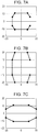
- Figs. 7A and 7B illustrate cases of arrangements of the magneto-electric transducers 31a to 31h on the circumferences of two different virtual ellipses oriented vertically.
- Fig. 7C illustrates a case of arrangement of the magneto-electric transducers 31a to 31h on the circumference of a virtual ellipse oriented horizontally.
- Figs. 8A to 8C illustrate output fluctuations (sensitivity changes) of the current sensors in displacement of the wire (the center of the wire) in a 0° (0-deg) direction (along a vertical axis), a 45° (45-deg) direction, and a 90° (90-deg) direction (along a horizontal axis) in the elliptical arrangements of Figs.
- a mechanism for allowing oblique wire displacement based on wire diameter is not limited to the mechanism including the support 13 and the binding band 50.
- Fig. 9A illustrates a modification of the embodiment.
- the inner walls 14 and 15 of the arms 11a and 11b are flat surfaces parallel to the major axis of the virtual ellipse and the inner wall 16 of the coupling part 11c is a flat surface perpendicular to the inner walls 14 and 15.
- the inner wall 15 of at least the one arm 11b perpendicularly intersects the inner wall 16 of the coupling part 11c.
- the inner wall 15 of the one arm 11b includes a first wire supporting portion 15a, serving as a flat abutment surface, near the intersection of the inner walls 15 and 16.
- the inner wall 16 of the coupling part 11c includes a second wire supporting portion 16a, serving as a flat abutment surface, near the intersection.
- a fastening member 70 configured to fasten the wire 60 is inserted through an opening between the arms 11a and 11b.
- the fastening member 70 has a bevel 70a at one end, serving as a leading end during insertion.
- the bevel 70a is inclined downward from the one arm 11a to the other arm 11b.
- the thickness (diameter) of the fastening member 70 is slightly smaller than the spacing between the arms 11a and 11b.
- the inner walls 14 and 15 of the arms 11a and 11b function to guide the fastening member 70.
- the fastening member 70 can be configured to be urged toward the coupling part 11c by an elastic member.
- the first wire supporting portion 15a, the second wire supporting portion 16a, and the bevel 70a may fasten the wire such that the center of the wire is located in a line extending in a direction in which a change in sensitivity caused by displacement of the wire is smaller than that in the direction along the major axis or the minor axis of the virtual ellipse.
- Such a configuration also allows the center of any of various wires having different diameters to be displaced obliquely relative to the major axis or the minor axis of the virtual ellipse when the wire is fastened by the band. Consequently, a change in sensitivity of the multiple magneto-electric transducers arranged on the circumference of the virtual ellipse caused by displacement of the wire in the major axis direction and that caused by displacement of the wire in the minor axis direction are canceled out, so that a change in sensitivity caused by displacement depending on wire diameter can be minimized.
- the bevel 70a presses the wire 60 toward the intersection of the first wire supporting portion 15a and the second wire supporting portion 16a.
- a force acts which presses the wire 60 in a direction at 45° relative to the direction along the major axis (or the minor axis) of the virtual ellipse. If the diameter of the wire 60 varies, a force similarly acts which presses the wire in the direction at 45° relative to the major axis direction (or the minor axis direction), so that the center of the wire 60 is displaced in the direction at 45°.
- a change in sensitivity of the current sensor 1 can be minimized.
- Fig. 9B illustrates another modification of the embodiment.
- the inner wall 15 of the arm 11b and the inner wall 16 of the coupling part 11c intersect at an acute angle smaller than 90°.
- the acute angle of intersection is formed by inclining the inner wall 16 of the coupling part 11c downward from the arm 11b to the arm 11a.
- the inner wall 15 of the arm 11b has a first wire supporting portion 15a, serving as a flat abutment surface, near the intersection.
- the inner wall 16 of the coupling part 11c has a second wire supporting portion 16a, serving as a flat abutment surface, near the intersection.
- a fastening member 70 configured to fasten the wire 60 is inserted through the opening between the arms 11a and 11b.
- the wire 60 pressed by the fastening member 70 is displaced slightly upward (toward the intersection) depending on the diameter of the wire 60 as compared with the case of Fig. 9A .
- the wire 60 is displaced slightly laterally depending on the diameter of the wire 60 as compared with the case of Fig. 9A .
- the bevel 70a of the fastening member 70 is orthogonal to the bisector of an angle formed by the first wire supporting portion 15a and the second wire supporting portion 16a. Since a force pressing the wire 60 is equally applied to the first wire supporting portion 15a and the second wire supporting portion 16a, the wire 60 is hard to move. Thus, stable fastening can be achieved.
- the fastening member 70 may include a proximal end that serves as a supporting portion and a distal end that serves as a movable portion and has the bevel 70a such that the proximal end is fixed to the arms 11a and 11b, and an elastic member (e.g., a spring) may be disposed between the distal end and the proximal end.
- an elastic member e.g., a spring
- the current sensor may include any magneto-electric transducers configured to output a signal based on an induced magnetic field from target current flowing through a wire.
- the magneto-electric transducer include various magnetoresistive elements, such as a giant magnetoresistive (GMR) element and a tunneling magnetoresistive (TMR) element, and various magnetic sensing elements, such as a Hall element.
- GMR giant magnetoresistive
- TMR tunneling magnetoresistive
Landscapes
- Physics & Mathematics (AREA)
- General Physics & Mathematics (AREA)
- Measuring Instrument Details And Bridges, And Automatic Balancing Devices (AREA)
Claims (11)
- Stromsensor (1), aufweisend:ein Gehäuse mit einem Paar von Armen (11a, 11b), die sich in der gleichen Richtung erstrecken, und mit einem Verbindungsbereich (11c), der die Arme (11a, 11b) verbindet;eine Mehrzahl von magnetoelektrischen Wandlern (31a-31h), die in dem Gehäuse untergebracht sind, wobei die magnetoelektrischen Wandler (31a-31h) entlang eines Umfangs einer virtuellen Ellipse (E) angeordnet sind, die eine erste Achse und eine zweite Achse aufweist, wobei die erste Achse eine von einer Hauptachse und einer Nebenachse der virtuellen Ellipse (E) ist, die sich zwischen und parallel zu den Armen (11a, 11b) erstreckt, und wobei die zweite Achse die andere von der Hauptachse und der Nebenachse ist; undeinen Befestigungsmechanismus, der dazu ausgebildet ist, einen Stromdraht (60) derart zwischen den Armen (11a, 11b) zu halten, dass der Stromdraht (60) bei unterschiedlichen Durchmessern des Stromdrahts (60) in einer ersten Richtung verlagert wird,dadurch gekennzeichnet, dass die erste Richtung in einem vorbestimmten schrägen Winkel (θ) von der ersten Achse in Richtung auf einen der Arme (11a, 11b) abgewinkelt ist.
- Stromsensor (1) nach Anspruch 1,
wobei der Befestigungsmechanismus aufweist:einen Befestigungsbereich (13), der gesehen von einem Zentrum des zwischen den Armen (11a, 11b) gehaltenen Stromdrahts (60) in der ersten Richtung an dem Gehäuse angeordnet ist; undein Band (50), das an dem Befestigungsbereich (13) angebracht ist, wobei das Band (50) den Stromdraht (60) an dem Befestigungsbereich (13) befestigt. - Stromsensor (1) nach Anspruch 2,
wobei der Befestigungsbereich (13) in Bezug auf die erste Achse schräg angeordnet ist, um gesehen von einem Zentrum eines zwischen den Armen (11a, 11b) angeordneten Stromdrahts (60) näher bei einem der Arme zu sein; und
wobei das Band (50) an dem Befestigungsbereich (13) angebracht ist, wobei das Band um eine Umfangsfläche des zwischen den Armen (11a, 11b) angeordneten Stromdrahts (60) herumgeführt ist, um den Stromdraht (60) derart zu befestigen, dass das Zentrum des Stromdrahts in Richtung auf den Befestigungsbereich (13) gezogen wird. - Stromsensor (1) nach Anspruch 3,
wobei der Befestigungsbereich (13) und das Band (50) den Stromdraht (60) derart halten, dass bei unterschiedlichen Durchmessern des Stromdrahts (60) das Zentrum des Stromdrahtss (60) in einer ersten Richtung verlagert wird, wobei eine Änderung der Empfindlichkeit, die durch die Verlagerung in der ersten Richtung verursacht wird, relativ geringer ist als die, die durch eine Verlagerung des Stromdrahts (60) in einer Richtung entlang der ersten Achse oder der zweiten Achse der virtuellen Ellipse (E) verursacht wird. - Stromsensor (1) nach Anspruch 4,
wobei der Befestigungsbereich (13) in einer Richtung angeordnet ist, die in einem Winkel von 45° von der ersten Achse in Richtung auf einen der Arme (11a, 11b) abgewinkelt ist. - Stromsensor (1) nach Anspruch 1,
wobei der Befestigungsmechanismus aufweist:einen ersten Drahtabstützbereich (15a), der an einer Innenwand von dem einen der Arme (11a, 11b) vorgesehen ist;einen zweiten Drahtabstützbereich (16a), der an einer Innenwand des Verbindungsbereichs (11c) vorgesehen ist; undein Befestigungselement (70), das zwischen den Armen (11a, 11b) angeordnet ist, wobei das Befestigungselement (70) eine geneigte Oberfläche (70a) aufweist, die von dem einen der Arme (11a, 11b) zu dem anderen geneigt ist, wobei die geneigte Oberfläche (70a) den Stromdraht (60) zwischen dem ersten Abstützbereich (15a) und dem zweiten Abstützbereich (16a) abstützt. - Stromsensor (1) nach Anspruch 6,
wobei der erste Drahtabstützbereich (15a), der zweite Drahtabstützbereich (16a) und die geneigte Oberfläche (70a) den Stromdraht (60) derart befestigen, dass das Zentrum des Stromdrahts (60) bei unterschiedlichen Durchmessern des Stromdrahts (60) in einer ersten Richtung verlagert wird, wobei eine Änderung der Empfindlichkeit, die durch die Verlagerung in der ersten Richtung verursacht wird, relativ geringer ist als die, die durch eine Verlagerung in einer Richtung entlang der ersten Achse oder der zweiten Achse der virtuellen Ellipse (E) verursacht wird. - Stromsensor (1) nach Anspruch 6 oder 7,
wobei der erste Drahtabstützbereich (15a), der zweite Drahtabstützbereich (16a) und die geneigte Oberfläche (70a) derart angeordnet sind, dass der Stromdraht (60) in eine Richtung gedrückt wird, die um 45° von der ersten Achse in Richtung auf den einen der Arme abgewinkelt ist. - Stromsensor (1) nach einem der Ansprüche 7 bis 8,
wobei die erste Richtung um 45° von der ersten Achse in Richtung auf den einen der Arme (11a, 11b) abgewinkelt ist. - Stromsensor (1) nach einem der Ansprüche 1 bis 9,
wobei eine Änderung der Empfindlichkeit, die durch eine Verlagerung in der ersten Richtung verursacht wird, relativ geringer ist als die, die durch eine Verlagerung des Stromdrahts (60) in einer Richtung entlang der ersten Achse oder der zweiten Achse der virtuellen Ellipse (E) verursacht wird. - Stromsensor (1) nach einem der Ansprüche 1 bis 10,
wobei der vorbestimmte Winkel (θ) etwa 45° beträgt.
Priority Applications (1)
| Application Number | Priority Date | Filing Date | Title |
|---|---|---|---|
| EP14160246.6A EP2921864B1 (de) | 2014-03-17 | 2014-03-17 | Stromsensor |
Applications Claiming Priority (1)
| Application Number | Priority Date | Filing Date | Title |
|---|---|---|---|
| EP14160246.6A EP2921864B1 (de) | 2014-03-17 | 2014-03-17 | Stromsensor |
Publications (2)
| Publication Number | Publication Date |
|---|---|
| EP2921864A1 EP2921864A1 (de) | 2015-09-23 |
| EP2921864B1 true EP2921864B1 (de) | 2020-07-29 |
Family
ID=50277136
Family Applications (1)
| Application Number | Title | Priority Date | Filing Date |
|---|---|---|---|
| EP14160246.6A Not-in-force EP2921864B1 (de) | 2014-03-17 | 2014-03-17 | Stromsensor |
Country Status (1)
| Country | Link |
|---|---|
| EP (1) | EP2921864B1 (de) |
Cited By (4)
| Publication number | Priority date | Publication date | Assignee | Title |
|---|---|---|---|---|
| LU503815B1 (de) | 2023-03-31 | 2024-09-30 | Phoenix Contact Gmbh & Co | Verfahren und Mess-Anordnung zur Messung der Stromstärke eines durch einen Leiter fließenden elektrischen Stroms |
| LU503820B1 (de) | 2023-03-31 | 2024-09-30 | Phoenix Contact Gmbh & Co | Messgerät zur kontaktlosen Strommessung und Verfahren zu dessen Kalibrierung |
| DE102023108272A1 (de) | 2023-03-31 | 2024-10-02 | Phoenix Contact Gmbh & Co. Kg | Verfahren und Mess-Anordnung zur Messung der Stromstärke eines durch einen Leiter fließenden elektrischen Stroms |
| DE102023108308A1 (de) | 2023-03-31 | 2024-10-02 | Phoenix Contact Gmbh & Co. Kg | Messgerät zur kontaktlosen Strommessung und Verfahren zu dessen Kalibrierung |
Family Cites Families (4)
| Publication number | Priority date | Publication date | Assignee | Title |
|---|---|---|---|---|
| DE3130277A1 (de) * | 1981-07-31 | 1983-02-17 | Vacuumschmelze Gmbh, 6450 Hanau | Magnetkern aus weichmagnetischem material fuer einen stromsensor mit einem magnetfeldabhaengigen halbleiterelement zur erfassung von gleich- und wechselstroemen |
| JP2006322706A (ja) | 2005-05-17 | 2006-11-30 | Uchihashi Estec Co Ltd | 導体電流の測定方法 |
| US8203328B2 (en) * | 2009-03-12 | 2012-06-19 | Consolidated Edison Company Of New York, Inc. | Current measuring device |
| EP2821798B1 (de) * | 2012-02-28 | 2016-12-07 | Alps Green Devices Co., Ltd. | Stromsensor |
-
2014
- 2014-03-17 EP EP14160246.6A patent/EP2921864B1/de not_active Not-in-force
Non-Patent Citations (1)
| Title |
|---|
| None * |
Cited By (6)
| Publication number | Priority date | Publication date | Assignee | Title |
|---|---|---|---|---|
| LU503815B1 (de) | 2023-03-31 | 2024-09-30 | Phoenix Contact Gmbh & Co | Verfahren und Mess-Anordnung zur Messung der Stromstärke eines durch einen Leiter fließenden elektrischen Stroms |
| LU503820B1 (de) | 2023-03-31 | 2024-09-30 | Phoenix Contact Gmbh & Co | Messgerät zur kontaktlosen Strommessung und Verfahren zu dessen Kalibrierung |
| DE102023108272A1 (de) | 2023-03-31 | 2024-10-02 | Phoenix Contact Gmbh & Co. Kg | Verfahren und Mess-Anordnung zur Messung der Stromstärke eines durch einen Leiter fließenden elektrischen Stroms |
| DE102023108308A1 (de) | 2023-03-31 | 2024-10-02 | Phoenix Contact Gmbh & Co. Kg | Messgerät zur kontaktlosen Strommessung und Verfahren zu dessen Kalibrierung |
| WO2024200483A1 (de) | 2023-03-31 | 2024-10-03 | Phoenix Contact Gmbh & Co. Kg | Messgerät zur kontaktlosen strommessung und verfahren zu dessen kalibrierung |
| WO2024200391A1 (de) | 2023-03-31 | 2024-10-03 | Phoenix Contact Gmbh & Co. Kg | VERFAHREN UND MESS-ANORDNUNG ZUR MESSUNG DER STROMSTÄRKE EINES DURCH EINEN LEITER FLIEßENDEN ELEKTRISCHEN STROMS |
Also Published As
| Publication number | Publication date |
|---|---|
| EP2921864A1 (de) | 2015-09-23 |
Similar Documents
| Publication | Publication Date | Title |
|---|---|---|
| US9423429B2 (en) | Current sensor | |
| US9575094B2 (en) | Current sensor for wires having different diameters | |
| CN102869995B (zh) | 电流检测装置 | |
| JP6712455B2 (ja) | 電流測定装置及び方法 | |
| JP4471657B2 (ja) | 電流センサ | |
| JP6661541B2 (ja) | クリップで留める電流変換器または変流器 | |
| US10048295B2 (en) | Current sensor | |
| JP6232080B2 (ja) | 電流センサ | |
| CN106104281A (zh) | 磁场传感器装置和具有其的电流转换器 | |
| EP3312618B1 (de) | Elektrischer stromtransformator | |
| EP2921864A1 (de) | Stromsensor | |
| JP6316516B2 (ja) | 磁気センサ装置 | |
| CN116359582A (zh) | 具有定位稳定性的电流感测 | |
| JP2019526805A (ja) | 多導体システムの1つの個別導体の電流強度を測定する装置および方法 | |
| EP3863150A1 (de) | Fehlausrichtungsdetektionsvorrichtung und spulenvorrichtung | |
| JP3757145B2 (ja) | 電流センサ | |
| JP6302607B1 (ja) | 電流センサ | |
| CN117310265A (zh) | 电流传感器设备 | |
| JP5798863B2 (ja) | 電流プローブ、電流プローブ計測システム及び電流プローブ計測方法 | |
| JP2015011021A (ja) | 電流センサー | |
| US12529714B2 (en) | Dual-channel current sensor | |
| JP7201129B2 (ja) | プローブおよび該プローブを備えるコネクタ検査装置 | |
| CN111640237B (zh) | 用于感测文件的磁安全特征的传感器装置及系统 | |
| JP2024088369A (ja) | センサユニット | |
| JP2019002708A (ja) | 電流センサ |
Legal Events
| Date | Code | Title | Description |
|---|---|---|---|
| PUAI | Public reference made under article 153(3) epc to a published international application that has entered the european phase |
Free format text: ORIGINAL CODE: 0009012 |
|
| AK | Designated contracting states |
Kind code of ref document: A1 Designated state(s): AL AT BE BG CH CY CZ DE DK EE ES FI FR GB GR HR HU IE IS IT LI LT LU LV MC MK MT NL NO PL PT RO RS SE SI SK SM TR |
|
| AX | Request for extension of the european patent |
Extension state: BA ME |
|
| 17P | Request for examination filed |
Effective date: 20160316 |
|
| RBV | Designated contracting states (corrected) |
Designated state(s): AL AT BE BG CH CY CZ DE DK EE ES FI FR GB GR HR HU IE IS IT LI LT LU LV MC MK MT NL NO PL PT RO RS SE SI SK SM TR |
|
| RAP1 | Party data changed (applicant data changed or rights of an application transferred) |
Owner name: ALPS ELECTRIC CO., LTD. |
|
| RAP1 | Party data changed (applicant data changed or rights of an application transferred) |
Owner name: ALPS ALPINE CO., LTD. |
|
| GRAP | Despatch of communication of intention to grant a patent |
Free format text: ORIGINAL CODE: EPIDOSNIGR1 |
|
| STAA | Information on the status of an ep patent application or granted ep patent |
Free format text: STATUS: GRANT OF PATENT IS INTENDED |
|
| RIC1 | Information provided on ipc code assigned before grant |
Ipc: G01R 15/20 20060101AFI20200317BHEP |
|
| INTG | Intention to grant announced |
Effective date: 20200401 |
|
| RIN1 | Information on inventor provided before grant (corrected) |
Inventor name: MITSUYA, SHINJI |
|
| GRAS | Grant fee paid |
Free format text: ORIGINAL CODE: EPIDOSNIGR3 |
|
| GRAA | (expected) grant |
Free format text: ORIGINAL CODE: 0009210 |
|
| STAA | Information on the status of an ep patent application or granted ep patent |
Free format text: STATUS: THE PATENT HAS BEEN GRANTED |
|
| AK | Designated contracting states |
Kind code of ref document: B1 Designated state(s): AL AT BE BG CH CY CZ DE DK EE ES FI FR GB GR HR HU IE IS IT LI LT LU LV MC MK MT NL NO PL PT RO RS SE SI SK SM TR |
|
| REG | Reference to a national code |
Ref country code: CH Ref legal event code: EP |
|
| REG | Reference to a national code |
Ref country code: AT Ref legal event code: REF Ref document number: 1296409 Country of ref document: AT Kind code of ref document: T Effective date: 20200815 |
|
| REG | Reference to a national code |
Ref country code: IE Ref legal event code: FG4D |
|
| REG | Reference to a national code |
Ref country code: DE Ref legal event code: R096 Ref document number: 602014068206 Country of ref document: DE |
|
| REG | Reference to a national code |
Ref country code: LT Ref legal event code: MG4D |
|
| REG | Reference to a national code |
Ref country code: NL Ref legal event code: MP Effective date: 20200729 |
|
| REG | Reference to a national code |
Ref country code: AT Ref legal event code: MK05 Ref document number: 1296409 Country of ref document: AT Kind code of ref document: T Effective date: 20200729 |
|
| PG25 | Lapsed in a contracting state [announced via postgrant information from national office to epo] |
Ref country code: FI Free format text: LAPSE BECAUSE OF FAILURE TO SUBMIT A TRANSLATION OF THE DESCRIPTION OR TO PAY THE FEE WITHIN THE PRESCRIBED TIME-LIMIT Effective date: 20200729 Ref country code: NO Free format text: LAPSE BECAUSE OF FAILURE TO SUBMIT A TRANSLATION OF THE DESCRIPTION OR TO PAY THE FEE WITHIN THE PRESCRIBED TIME-LIMIT Effective date: 20201029 Ref country code: SE Free format text: LAPSE BECAUSE OF FAILURE TO SUBMIT A TRANSLATION OF THE DESCRIPTION OR TO PAY THE FEE WITHIN THE PRESCRIBED TIME-LIMIT Effective date: 20200729 Ref country code: PT Free format text: LAPSE BECAUSE OF FAILURE TO SUBMIT A TRANSLATION OF THE DESCRIPTION OR TO PAY THE FEE WITHIN THE PRESCRIBED TIME-LIMIT Effective date: 20201130 Ref country code: HR Free format text: LAPSE BECAUSE OF FAILURE TO SUBMIT A TRANSLATION OF THE DESCRIPTION OR TO PAY THE FEE WITHIN THE PRESCRIBED TIME-LIMIT Effective date: 20200729 Ref country code: LT Free format text: LAPSE BECAUSE OF FAILURE TO SUBMIT A TRANSLATION OF THE DESCRIPTION OR TO PAY THE FEE WITHIN THE PRESCRIBED TIME-LIMIT Effective date: 20200729 Ref country code: AT Free format text: LAPSE BECAUSE OF FAILURE TO SUBMIT A TRANSLATION OF THE DESCRIPTION OR TO PAY THE FEE WITHIN THE PRESCRIBED TIME-LIMIT Effective date: 20200729 Ref country code: ES Free format text: LAPSE BECAUSE OF FAILURE TO SUBMIT A TRANSLATION OF THE DESCRIPTION OR TO PAY THE FEE WITHIN THE PRESCRIBED TIME-LIMIT Effective date: 20200729 Ref country code: GR Free format text: LAPSE BECAUSE OF FAILURE TO SUBMIT A TRANSLATION OF THE DESCRIPTION OR TO PAY THE FEE WITHIN THE PRESCRIBED TIME-LIMIT Effective date: 20201030 Ref country code: BG Free format text: LAPSE BECAUSE OF FAILURE TO SUBMIT A TRANSLATION OF THE DESCRIPTION OR TO PAY THE FEE WITHIN THE PRESCRIBED TIME-LIMIT Effective date: 20201029 |
|
| PG25 | Lapsed in a contracting state [announced via postgrant information from national office to epo] |
Ref country code: PL Free format text: LAPSE BECAUSE OF FAILURE TO SUBMIT A TRANSLATION OF THE DESCRIPTION OR TO PAY THE FEE WITHIN THE PRESCRIBED TIME-LIMIT Effective date: 20200729 Ref country code: LV Free format text: LAPSE BECAUSE OF FAILURE TO SUBMIT A TRANSLATION OF THE DESCRIPTION OR TO PAY THE FEE WITHIN THE PRESCRIBED TIME-LIMIT Effective date: 20200729 Ref country code: RS Free format text: LAPSE BECAUSE OF FAILURE TO SUBMIT A TRANSLATION OF THE DESCRIPTION OR TO PAY THE FEE WITHIN THE PRESCRIBED TIME-LIMIT Effective date: 20200729 Ref country code: IS Free format text: LAPSE BECAUSE OF FAILURE TO SUBMIT A TRANSLATION OF THE DESCRIPTION OR TO PAY THE FEE WITHIN THE PRESCRIBED TIME-LIMIT Effective date: 20201129 |
|
| PG25 | Lapsed in a contracting state [announced via postgrant information from national office to epo] |
Ref country code: NL Free format text: LAPSE BECAUSE OF FAILURE TO SUBMIT A TRANSLATION OF THE DESCRIPTION OR TO PAY THE FEE WITHIN THE PRESCRIBED TIME-LIMIT Effective date: 20200729 |
|
| PG25 | Lapsed in a contracting state [announced via postgrant information from national office to epo] |
Ref country code: IT Free format text: LAPSE BECAUSE OF FAILURE TO SUBMIT A TRANSLATION OF THE DESCRIPTION OR TO PAY THE FEE WITHIN THE PRESCRIBED TIME-LIMIT Effective date: 20200729 Ref country code: DK Free format text: LAPSE BECAUSE OF FAILURE TO SUBMIT A TRANSLATION OF THE DESCRIPTION OR TO PAY THE FEE WITHIN THE PRESCRIBED TIME-LIMIT Effective date: 20200729 Ref country code: EE Free format text: LAPSE BECAUSE OF FAILURE TO SUBMIT A TRANSLATION OF THE DESCRIPTION OR TO PAY THE FEE WITHIN THE PRESCRIBED TIME-LIMIT Effective date: 20200729 Ref country code: CZ Free format text: LAPSE BECAUSE OF FAILURE TO SUBMIT A TRANSLATION OF THE DESCRIPTION OR TO PAY THE FEE WITHIN THE PRESCRIBED TIME-LIMIT Effective date: 20200729 Ref country code: SM Free format text: LAPSE BECAUSE OF FAILURE TO SUBMIT A TRANSLATION OF THE DESCRIPTION OR TO PAY THE FEE WITHIN THE PRESCRIBED TIME-LIMIT Effective date: 20200729 Ref country code: RO Free format text: LAPSE BECAUSE OF FAILURE TO SUBMIT A TRANSLATION OF THE DESCRIPTION OR TO PAY THE FEE WITHIN THE PRESCRIBED TIME-LIMIT Effective date: 20200729 |
|
| PGFP | Annual fee paid to national office [announced via postgrant information from national office to epo] |
Ref country code: FR Payment date: 20210323 Year of fee payment: 8 |
|
| REG | Reference to a national code |
Ref country code: DE Ref legal event code: R097 Ref document number: 602014068206 Country of ref document: DE |
|
| PG25 | Lapsed in a contracting state [announced via postgrant information from national office to epo] |
Ref country code: AL Free format text: LAPSE BECAUSE OF FAILURE TO SUBMIT A TRANSLATION OF THE DESCRIPTION OR TO PAY THE FEE WITHIN THE PRESCRIBED TIME-LIMIT Effective date: 20200729 |
|
| PGFP | Annual fee paid to national office [announced via postgrant information from national office to epo] |
Ref country code: DE Payment date: 20210319 Year of fee payment: 8 |
|
| PLBE | No opposition filed within time limit |
Free format text: ORIGINAL CODE: 0009261 |
|
| STAA | Information on the status of an ep patent application or granted ep patent |
Free format text: STATUS: NO OPPOSITION FILED WITHIN TIME LIMIT |
|
| PG25 | Lapsed in a contracting state [announced via postgrant information from national office to epo] |
Ref country code: SK Free format text: LAPSE BECAUSE OF FAILURE TO SUBMIT A TRANSLATION OF THE DESCRIPTION OR TO PAY THE FEE WITHIN THE PRESCRIBED TIME-LIMIT Effective date: 20200729 |
|
| 26N | No opposition filed |
Effective date: 20210430 |
|
| PG25 | Lapsed in a contracting state [announced via postgrant information from national office to epo] |
Ref country code: SI Free format text: LAPSE BECAUSE OF FAILURE TO SUBMIT A TRANSLATION OF THE DESCRIPTION OR TO PAY THE FEE WITHIN THE PRESCRIBED TIME-LIMIT Effective date: 20200729 |
|
| PG25 | Lapsed in a contracting state [announced via postgrant information from national office to epo] |
Ref country code: MC Free format text: LAPSE BECAUSE OF FAILURE TO SUBMIT A TRANSLATION OF THE DESCRIPTION OR TO PAY THE FEE WITHIN THE PRESCRIBED TIME-LIMIT Effective date: 20200729 |
|
| REG | Reference to a national code |
Ref country code: CH Ref legal event code: PL |
|
| GBPC | Gb: european patent ceased through non-payment of renewal fee |
Effective date: 20210317 |
|
| REG | Reference to a national code |
Ref country code: BE Ref legal event code: MM Effective date: 20210331 |
|
| PG25 | Lapsed in a contracting state [announced via postgrant information from national office to epo] |
Ref country code: LI Free format text: LAPSE BECAUSE OF NON-PAYMENT OF DUE FEES Effective date: 20210331 Ref country code: LU Free format text: LAPSE BECAUSE OF NON-PAYMENT OF DUE FEES Effective date: 20210317 Ref country code: CH Free format text: LAPSE BECAUSE OF NON-PAYMENT OF DUE FEES Effective date: 20210331 Ref country code: IE Free format text: LAPSE BECAUSE OF NON-PAYMENT OF DUE FEES Effective date: 20210317 Ref country code: GB Free format text: LAPSE BECAUSE OF NON-PAYMENT OF DUE FEES Effective date: 20210317 |
|
| PG25 | Lapsed in a contracting state [announced via postgrant information from national office to epo] |
Ref country code: BE Free format text: LAPSE BECAUSE OF NON-PAYMENT OF DUE FEES Effective date: 20210331 |
|
| REG | Reference to a national code |
Ref country code: DE Ref legal event code: R119 Ref document number: 602014068206 Country of ref document: DE |
|
| PG25 | Lapsed in a contracting state [announced via postgrant information from national office to epo] |
Ref country code: FR Free format text: LAPSE BECAUSE OF NON-PAYMENT OF DUE FEES Effective date: 20220331 Ref country code: DE Free format text: LAPSE BECAUSE OF NON-PAYMENT OF DUE FEES Effective date: 20221001 |
|
| PG25 | Lapsed in a contracting state [announced via postgrant information from national office to epo] |
Ref country code: HU Free format text: LAPSE BECAUSE OF FAILURE TO SUBMIT A TRANSLATION OF THE DESCRIPTION OR TO PAY THE FEE WITHIN THE PRESCRIBED TIME-LIMIT; INVALID AB INITIO Effective date: 20140317 |
|
| PG25 | Lapsed in a contracting state [announced via postgrant information from national office to epo] |
Ref country code: CY Free format text: LAPSE BECAUSE OF FAILURE TO SUBMIT A TRANSLATION OF THE DESCRIPTION OR TO PAY THE FEE WITHIN THE PRESCRIBED TIME-LIMIT Effective date: 20200729 |
|
| PG25 | Lapsed in a contracting state [announced via postgrant information from national office to epo] |
Ref country code: MK Free format text: LAPSE BECAUSE OF FAILURE TO SUBMIT A TRANSLATION OF THE DESCRIPTION OR TO PAY THE FEE WITHIN THE PRESCRIBED TIME-LIMIT Effective date: 20200729 |
|
| PG25 | Lapsed in a contracting state [announced via postgrant information from national office to epo] |
Ref country code: TR Free format text: LAPSE BECAUSE OF FAILURE TO SUBMIT A TRANSLATION OF THE DESCRIPTION OR TO PAY THE FEE WITHIN THE PRESCRIBED TIME-LIMIT Effective date: 20200729 |
|
| PG25 | Lapsed in a contracting state [announced via postgrant information from national office to epo] |
Ref country code: MT Free format text: LAPSE BECAUSE OF FAILURE TO SUBMIT A TRANSLATION OF THE DESCRIPTION OR TO PAY THE FEE WITHIN THE PRESCRIBED TIME-LIMIT Effective date: 20200729 |