EP2921960A2 - Procédé et appareil de récupération accélérée de données dans un système de stockage - Google Patents
Procédé et appareil de récupération accélérée de données dans un système de stockage Download PDFInfo
- Publication number
- EP2921960A2 EP2921960A2 EP14170168.0A EP14170168A EP2921960A2 EP 2921960 A2 EP2921960 A2 EP 2921960A2 EP 14170168 A EP14170168 A EP 14170168A EP 2921960 A2 EP2921960 A2 EP 2921960A2
- Authority
- EP
- European Patent Office
- Prior art keywords
- target objects
- stripe
- matrix
- defining
- units
- Prior art date
- Legal status (The legal status is an assumption and is not a legal conclusion. Google has not performed a legal analysis and makes no representation as to the accuracy of the status listed.)
- Withdrawn
Links
Images



Classifications
-
- G—PHYSICS
- G06—COMPUTING OR CALCULATING; COUNTING
- G06F—ELECTRIC DIGITAL DATA PROCESSING
- G06F11/00—Error detection; Error correction; Monitoring
- G06F11/07—Responding to the occurrence of a fault, e.g. fault tolerance
- G06F11/08—Error detection or correction by redundancy in data representation, e.g. by using checking codes
- G06F11/10—Adding special bits or symbols to the coded information, e.g. parity check, casting out 9's or 11's
- G06F11/1076—Parity data used in redundant arrays of independent storages, e.g. in RAID systems
-
- G—PHYSICS
- G06—COMPUTING OR CALCULATING; COUNTING
- G06F—ELECTRIC DIGITAL DATA PROCESSING
- G06F11/00—Error detection; Error correction; Monitoring
- G06F11/07—Responding to the occurrence of a fault, e.g. fault tolerance
- G06F11/08—Error detection or correction by redundancy in data representation, e.g. by using checking codes
- G06F11/10—Adding special bits or symbols to the coded information, e.g. parity check, casting out 9's or 11's
- G06F11/1076—Parity data used in redundant arrays of independent storages, e.g. in RAID systems
- G06F11/1092—Rebuilding, e.g. when physically replacing a failing disk
-
- G—PHYSICS
- G06—COMPUTING OR CALCULATING; COUNTING
- G06F—ELECTRIC DIGITAL DATA PROCESSING
- G06F11/00—Error detection; Error correction; Monitoring
- G06F11/07—Responding to the occurrence of a fault, e.g. fault tolerance
- G06F11/08—Error detection or correction by redundancy in data representation, e.g. by using checking codes
- G06F11/10—Adding special bits or symbols to the coded information, e.g. parity check, casting out 9's or 11's
- G06F11/1008—Adding special bits or symbols to the coded information, e.g. parity check, casting out 9's or 11's in individual solid state devices
Definitions
- the present invention relates to a method of, and apparatus for, accelerated data recovery in a storage system.
- Performance and data integrity are core requirements for modern storage systems.
- the ability to prevent and, if necessary, identify and correct data errors and corruptions is essential for operation of storage systems ranging from a simple hard disk drive up to large mainframe storage arrays.
- RAID arrays are the primary storage architecture for large, networked computer storage systems.
- RAID architecture was first disclosed in "A Case for Redundant Arrays of Inexpensive Disks (RAID)", Patterson, Gibson, and Katz (University of California, Berkeley). RAID architecture combines multiple small, inexpensive disk drives into an array of disk drives that yields performance exceeding that of a single large drive.
- RAID-1 through RAID-6 There are a number of different RAID architectures, designated as RAID-1 through RAID-6. Each architecture offers disk fault-tolerance and offers different trade-offs in terms of features and performance. In addition to the different architectures, a non-redundant array of disk drives is referred to as a RAID-0 array. RAID controllers provide data integrity through redundant data mechanisms, high speed through streamlined algorithms, and accessibility to stored data for users and administrators.
- RAID architectures provide data redundancy in two basic forms: mirroring (RAID 1) and parity (RAID 3, 4, 5 and 6).
- the implementation of mirroring in RAID 1 architectures involves creating an identical image of the data on a primary disk on a secondary disk. The contents of the primary and secondary disks in the array are identical.
- RAID 1 architecture requires at least two drives and has increased reliability when compared to a single disk.
- RAID 3, 4, 5, or 6 architectures generally utilise three or more disks of identical capacity. In RAID 3 or 4 architectures, two or more of the disks are utilised for reading/writing of data and one or more of the disks store parity information.
- RAID 5 and 6 architectures comprise "distributed parity" architectures in which the data and parity data are interleaved across the disks.
- Data interleaving across the disks is usually in the form of data "striping" in which the data to be stored is broken down into stripe groups comprising a plurality of blocks called “stripe units”. The “stripe units” are then distributed across the disks.
- RAID 5 and 6 arrangements are particularly robust with regard to drive failure.
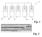
- Figure 1 shows a plurality of disk drives 10a-e forming a RAID 6 array 12. In Figure 1 , five drives are shown. However, any suitable number could be used. Each disk drive 10a-e can be accessed through a RAID controller to read/write data.
- data is stored on the RAID 6 array 108 in the form of stripe groups comprising stripe units.
- Each stripe group A, B comprises five separate stripe units - stripe A comprises stripes A1, A2, A3, A p and Aq.
- Stripe B comprises stripe units B1, B2, B3, B p and Bq. Therefore, the stripe units comprising each stripe (A1-A3 or B1-B3 respectively) are distributed across a plurality of disk drives, together with parity information A p and Aq and B p and Bq respectively. This provides data redundancy.
- the arrangement, format, parameters and configuration of the particular stripe units across the drives of a RAID array is known as the layout.
- the layout may include, non-exhaustively, RAID array configuration parameters such as, for example, information on the distribution of particular stripe groups, the number and size of the stripe units within those stripe groups, the size of the checksum symbols.
- each stripe unit in a stripe group is mapped to a different storage component in the array as a contiguous chunk of data.
- To map each stripe unit to a disk storage component creates two desirable properties. Firstly, most common I/O workloads can be parallelised across the storage components 10a-e forming the RAID array 12. Secondly, should a storage component fail, only one stripe unit in a stripe group will affected, aiding recovery.
- stripe units in a stripe group will store data whereas others will store redundancy (checksum) parity information. Further, some implementations may reserve stripe units as distributed spare space inside of the RAID array for the purpose of accelerated recovery from storage component failures.
- the layout is a function of the particular RAID software and is known as the layout.
- the layout is selected to eliminate areas of particularly high activity on the array and maximise performance of the array.
- Parity declustered RAID is a technique which, in the event of a drive failure, reduces the amount of work for each surviving drive.
- PDRAID Parity declustered RAID
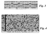
- FIG. 2 An example of such a matrix is shown in Figure 2 .
- Each matrix is arranged such that the number of columns is equal to the number of hard drives in the array (i.e. the drive count).
- the columns are then divided into rows of equally offset units across those hard drives.
- a unit is a fixed width block of contiguously addressed information that is measured in bytes. Units are analogous to chunks and in PDRAID all units are of equal length. In practice, the unit size is equal to the chunk size of the array.
- Units may contain data or parity information, or may be reserved as spare space.
- the set of all units in a configuration are enumerated and ordered; this set is referred to as the unit-address space.
- a further criterion imposed is that the final stripe-group ends on the last drive.
- the number of rows in the matrix is then the least common multiple of the drive count and the stripe width, divided by the drive count.
- Figure 2 shows an exemplary matrix illustrating an arrangement comprising 15 hard drives.
- the data is arranged in a plurality of stripe groups.
- Each stripe group has a stripe width equal to the total number of units in the stripe group.
- the stripe groups are arranged in a 5+2 configuration, meaning that for every stripe group there are 5 data units and 2 parity units.
- the example of Figure 2 is comprised of 15 stripe-groups and is the minimum number of stripe-groups that a) spans all drives and b) ends on a row boundary (the last 'Q' unit of stripe group 14 lands on the last drive). Because stripe-groups are mapped sequentially over the matrix space, it is ensured that each unit in a stripe-group maps to a different hard drive. Therefore, if any one hard drive fails, then at most one unit in any stripe-group is lost.
- each unit in the first column belongs to a different stripe group.
- each column is pseudo-randomly assigned to a particular drive such that the sequence of data down each column (i.e. on any given hard drive) remains the same, but that the particular hard drive to which that data sequence is assigned can be varied according to a pseudo-random computation.
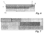
- FIG. 3 shows an alternative matrix layout utilising this approach.
- each matrix is permuted uniquely according to a pseudo-random permutation selection procedure.
- MTTR mean time to repair
- MTTF mean time to failure
- a hard disk drive performs best when its workload is sequential. Many modern hard disks provide sequential workload optimisations, such as read ahead caching to a read ahead storage buffer. Therefore, during data access or recovery, an individual hard drive in the array may operate under one of the following three conditions:
- the first case is when individual units, spaced apart on the hard drive, are accessed as part of a read or rebuilding operation. In this situation, no read ahead can be utilised.
- the second case is where units to be read are grouped in small clusters. Read ahead can occur, but is limited due to the size of the clusters of units being read. Therefore, the capacity of the read ahead buffer is not fully utilised and the performance is not optimised.
- the third case is where units to be read are clustered in such an arrangement that the data units can utilise read ahead and make full use of the capability of the read ahead storage buffer.
- the ability to utilise fully the capabilities of the read ahead buffer means that, under these conditions, the requisite units on the hard drive can be accessed much more quickly than under the first two conditions.
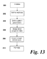
- Figure 4 shows a 35 hard drive, 8+2 PDRAID arrangement in accordance with the above-described PDRAID pseudo-random arrangement.
- hard drive 4 has failed (as shown by the dark column). To reconstruct the data on the failed drive 4, it is necessary to access all of the units highlighted in grey.
- the data access pattern for reconstruction is highly scattered. Looking down a given column (which represents the units on a particular hard drive), the units which must be accessed to reconstruct the data are arranged either in small clusters or stand alone. In other words, the recovery workload is incoherent.
- the present invention acknowledges, for the first time, that known PDRAID configurations are incapable of providing a data configuration in which reconstruction and recovery data access is optimised.
- Embodiments of the present invention seek to address this issue.
- a method of defining a layout mapping function for a parity distributed RAID array comprising a plurality of target objects, the layout mapping function defining the mapping of the group-address space to the target-address space in the array and comprising a matrix defining a unit space across a plurality of target objects, the matrix comprises columns defining said target objects and rows defining equally-offset sequential units on said target objects, the method comprising: a) defining a layout of stripe groups across the target objects by defining a pattern comprising a plurality of stripe groups and repeating said pattern across said matrix, each stripe group comprising a plurality of data units and a plurality of parity units; and b) implementing said layout on said target objects of said RAID array.
- said pattern is defined by a width parameter, said width parameter specifying the number of stripe groups to be distributed across said columns of said matrix before said pattern is repeated into the subjacent row.
- said width parameter is greater than 1.
- said width parameter is selected as the integer of the number of target objects divided by the number of units in a stripe group.
- said pattern is defined by a repeat parameter, said repeat parameter specifying the number of stripe groups to be distributed sequentially down said rows of said matrix before before traversing "horizontally" to the next set of columns in said matrix.
- said repeat parameter is greater than 1.
- said repeat parameter is greater than 8.
- said target objects comprise hard drives forming part of the RAID array and said repeat parameter is set based on a parameter equal to the read ahead disk size of one or more hard drives divided by the size of the units on said one or more hard drives.
- said target objects comprise hard drives forming part of a RAID array.
- the method further comprises: c) permuting said columns to assign different columns to different target objects.
- step c) said permutation involves pseudo-random permutation.
- each of said patterns comprises two or more stripe groups.
- apparatus operable to define a layout mapping function for a parity distributed RAID array comprising a plurality of target objects, the layout mapping function defining the mapping of the group-address space to the target-address space in the array and comprising a matrix defining a unit space across a plurality of target objects, the matrix comprises columns defining said target objects and rows defining sequential units on said target objects, the computing apparatus being operable to: a) define a layout of stripe groups across the target objects by defining a pattern comprising a plurality of stripe groups and repeating said pattern across said matrix, each stripe group comprising a plurality of data units and a plurality of parity units; and b) implement said layout on said target objects of said RAID array.
- said width parameter is greater than 1.
- said width parameter is selected as the integer of the number of target objects divided by the number of units in a stripe group.
- said pattern is defined by a repeat parameter, said repeat parameter specifying the number of stripe groups to be distributed sequentially down said rows of said matrix before said pattern is repeated.
- said repeat parameter is greater than 1.
- said target objects comprise hard drives forming part of a RAID array.
- the apparatus prior to step b), is further operable to:
- non-transitory computer readable storage medium having stored thereon a computer program product executable by a programmable processing apparatus, comprising one or more software portions for performing the steps of the first aspect.
- the present invention aims to rearrange the layout of a RAID array so that read ahead can be leveraged uniformly.
- a modification to known nearly random permutations algorithm is applied which enables stripe-groups to be distributed in a manner that improves the sequentiality of the recovery workload and thus reduces MTTR and, consequently, increases MTTF.
- FIG. 5 shows a schematic diagram of a storage resource 100 that may be used with the present invention.
- the storage resource 100 comprises a host 102, a RAID controller 104, and storage devices 106a, 106b, 106c, 106d and 106e which, together, form part of a RAID 6 array 108.
- the host 102 is connected to the RAID controller 104 through a communication network 110 such as an Ethernet and the RAID controller 104 is, in turn, connected to the storage devices 106a-e via a storage network 112 such as an iSCSI network.
- a communication network 110 such as an Ethernet
- the RAID controller 104 is, in turn, connected to the storage devices 106a-e via a storage network 112 such as an iSCSI network.
- the host 102 comprises a general purpose computer (PC) which is operated by a user and which has access to the storage resource 100.
- a graphical user interface (GUI) 114 is run on the host 102.
- the GUI 114 is a software application which acts as a user interface for a user of the host 102.
- the RAID controller 104 comprises a software application layer 116, an operating system 118 and RAID controller hardware 120.
- the software application layer 116 comprises software applications including the algorithms and logic necessary for the initialisation and run-time operation of the RAID controller 104.
- the software application layer 116 includes software functional blocks such as a system manager for fault management, task scheduling and power management.
- the software application layer 116 also receives commands from the host 102 (e.g., assigning new volumes, read/write commands) and executes those commands. Commands that cannot be processed (because of lack of space available, for example) are returned as error messages to the user of the host 102.
- the operation of the RAID controller 104 may be set at the Application Programming Interface (API) level.
- API Application Programming Interface
- OEMs Original Equipment Manufactures
- OEMs provide RAID networks to end users for network storage. OEMs generally customise a RAID network and tune the network performance through an API.
- the operating system 118 utilises an industry-standard software platform such as, for example, Linux, upon which the software applications forming part of the software application layer 116 can run.
- the operating system 118 comprises a file system 118a which enables the RAID controller 104 to store and transfer files and interprets the data stored on the primary and secondary drives into, for example, files and directories for use by the operating system 118.
- the RAID controller hardware 120 is the physical processor platform of the RAID controller 104 that executes the software applications in the software application layer 116.
- the RAID controller hardware 120 comprises a microprocessor, memory 122, and all other electronic devices necessary for RAID control of the storage devices 106a-e.
- the storage devices 106 may take any suitable form; for example, tape drives, disk drives, non-volatile memory, or solid state devices. Although most RAID architectures use hard disk drives as the main storage devices, it will be clear to the person skilled in the art that the embodiments described herein apply to any type of suitable storage device. More than one drive may form a storage device 106; for example, a RAID array of drives may form a single storage device 106. The skilled person will be readily aware that the above features of the present embodiment could be implemented in a variety of suitable configurations and arrangements.
- the term "storage device” in the context of the following description may refer to a logical drive which is formed on the RAID array 108.
- a sector refers to a portion of the logical drive created on the RAID array 108.
- the following embodiment of the present invention is applicable to any of the above described arrangements.
- each sector comprises 512 bytes (4096 bits).
- the term "sector” used herein is generally applicable to any sector sizes. Therefore, the term “sector” is merely intended to indicate a portion of the storage availability on a storage device and is not intended to be limited to any of the disclosed examples. Additionally, sector may be used to refer to a portion of a logical drive, i.e. a virtual drive created from a plurality of physical hard drives linked together in a RAID configuration.
- any number of RAID controllers 104 may be provided to serve any number of storage devices forming an array.
- the RAID controller 104 stores configuration metadata for the RAID array 108. This denotes the configuration of data storage on the RAID array 108 as described above.
- the present invention is concerned with improved arrangements of data configuration as will be described below.
- the following embodiment of the invention may be utilised with the above RAID arrangement.
- a single storage device 106a will be referred to.
- the embodiment of the invention is equally applicable to other arrangements; for example, the storage device 106a may be a logical drive, or may be a single hard disk drive.
- the configuration of the data on the RAID array 108 is governed by the configuration data as set out in one or more matrices.
- the present invention seeks to provide matrix configurations in which the benefits of PDRAID are preserved, but under which recovery can occur much more quickly by taking advantage of the properties of modern hard disk drives.
- a matrix represents a part of a layout mapping function for the RAID array. The following parameters as utilised by the present invention will be described below.
- a unit is the smallest block of information handled by the matrix. As described above, a unit is a fixed width block of contiguously addressed information that is measured in bytes. Units are analogous with chunks and in PDRAID all units are of equal length. Units may contain data or parity information, or may be reserved as sparing space. The set of all units in a configuration are enumerated and ordered; this set is referred to as the unit-address space.
- a target object is a storage entity (in this embodiment, a hard drive) that is divided into "frames".
- the capacity of a frame is equal to unit length and as such a frame stores precisely one unit of information.
- a pool is a collection of target objects. There are P target objects in a pool.
- a stripe group is a set of data units and parity units. Each unit in a stripe group is identified as a (group number, unit number) ordered pair.
- Target address space 0 0 0 1 0 2 0 3 1 0 1 1 1 2 1 3 2 0 2 1 2 2 2 3 ... .
- Table 1 An example is shown in Table 1 below: Table 1 Target 0 Target 1 Target 2 Target 3 frame 0 frame 0 frame 0 frame 0 frame 1 frame 1 frame 1 frame 1 frame 2 frame 2 frame 2 frame 2 .. ... ... ...
- the target address space is thought of as an array of frame rows and target columns, then the set is row-major ordered.
- the unit-address space is laid out sequentially over the target-address space and therefore the target-address space can be redrawn as follows: Table 2 Target 0 Target 1 Target 2 Target 3 unit 0 unit 1 unit 2 unit 3 unit 4 unit 5 unit 6 unit 7 unit 8 unit 9 unit 10 unit 11 ... ... ... ...
- a layout is then the mapping of the stripe group-address space to the target-address space.
- each (group number, unit number) element maps to a unique (frame number, target number) element.
- the matrix construct is then used as part of the layout function.
- a PDRAID array configuration is denoted as set out in expression 1): P ⁇ N + K + A RxW where P is the number of target devices in the array, N is the number of data units per stripe-group, K is the number of parity units per stripe-group, and A is the number of distributed spares.
- Distributed spares are spare space which is pseudo-randomly distributed within the matrix configuration. Whilst embodiments and implementations utilising distributed spares are intended to fall within the scope of the present invention, for brevity they will not be described further here. Therefore, for the purposes of the following exemplary embodiments, A will be set to zero.
- the parameters R and W are aspects of the present invention which enable efficient optimisation of a RAID configuration.
- One aspect of the present invention is to map stripe-groups across the hard drives in a matrix in sequential patterns to enable efficient access to the data in the event of a drive failure requiring a rebuilding operation.
- a set of stripe groups is mapped into the matrix space in a given pattern and then the pattern is repeated sequentially on disk, so that stripe-groups are effectively stacked.
- Parameter W is known as the width and represents how many stripe-groups are laid out along the columns across the matrix before the pattern is repeated.
- Parameter R is the repeat count, and specifies along how many rows the pattern is to be repeated.
- parameters W and R can be likened to X and Y axes of a matrix respectively, with the value of W for a given pattern denoting how many sequential stripe groups extend in the "X axis" of the pattern and the value of R determining how many stripe groups extend in the "Y-axis" of the pattern.
- W x R the total number of stripe groups in a given pattern is equal to W x R.
- a pattern can therefore be defined as a sub-matrix within the matrix, where the sub-matrix has dimensions of W x R stripe groups.
- the width W can be larger than this, but this may cause skipping in the access pattern.
- the width W can also be less, though this will reduce the amount of parallelism that can be achieved when presented with low-queue-depth IO.
- Figure 6 illustrates a basic example of this.
- Figure 6 shows a 20 drive matrix in which the stripe groups comprise 4 data units and 2 parity units in a [20 (4+2)] configuration.
- stripe groups 0 to 2 extend along the first row, then stripe groups 3 to 5 along the second row and so on. The pattern is then repeated for later stripe groups.
- Figure 7 shows a 29 drive matrix in which the stripe groups comprise 5 data units and 2 parity units in a [29 (5+2) ] configuration.
- the first pattern shown in a black box
- stripe group 0 only the first stripe group (stripe group 0) extends across the drives, with stripe groups 1 to 4 arranged below.
- individual units in stripe groups 0 to 4 are arranged sequentially along a row (i.e. on a given drive). This pattern is then repeated for all stripe groups.
- Figure 8 shows a similar 29 drive matrix in which the stripe groups comprise 5 data units and 2 parity units in a [29 (5+2) ] configuration.
- the first to third stripe groups extends across the drives, with stripe groups 3 to 5 arranged below and so on.
- individual units in stripe groups 0, 3, 6, 9 and 12 are arranged sequentially along a row (i.e. on a given drive) in the pattern.
- Figure 9 is provided to contrast the above examples with a known arrangement.
- Figure 9 shows a similar 29 drive matrix in which the stripe groups comprise 5 data units and 2 parity units in a [29 (5+2)] configuration.
- the matrix of Figure 9 comprises no pattern of stripe groups.
- R and W the situation reduces to that known in the art where stripe groups are not laid out in any pattern and are just distributed sequentially across the whole matrix.
- the first to third stripe groups extends across the drives, with stripe groups 3 to 5 arranged below and so on.
- individual units in stripe groups 0, 3, 6, 9 and 12 are arranged sequentially along a row (i.e. on a given drive) in the pattern.
- stripe groups are aligned onto the same hard disks as required.
- W becomes a more critical parameter as the value of R increases.
- W 1 and R is increased.
- W more and more client I/O data is required to fill the pattern of repeated stripes and begin to access a different set of hard disks.
- a bottleneck may be created on a few disks due to the lack of parallelism.
- Figure 10 shows the benefit of this approach in practice.
- the hard disk read ahead mechanism can be utilised and cached read ahead data will be utilised.
- the arrangement enables much faster rebuilding of the drive.
- each pattern comprises a plurality of stripe groups, as set out in the above embodiments.
- such patterns are generally beneficial due to reduce gaps and seeking latencies in the workload.
- a further advantage of this approach is that when matrix permutations are cached, the cost of calculating a permutation is amortized over a larger space given a sequential access pattern such as repair.
- Figure 11 shows an example of how recovery repair performance improves as the repeating parameter R increases. This test was conducted with a 41 hard drive PDRAID array, with stripe groups comprising 10 units - 8 data and 2 parity. A single distributed spare is provided, defining this test example as a [41 (8+2+1) Rx1] PDRAID array.
- Figure 12 shows a similar graph illustrating how recovery repair performance improves as R increases. This test was conducted with a 41 hard drive PDRAID array, with stripe groups comprising 10 units - 8 data and 2 parity. Two distributed spares are provided, defining this test example as a standard [41 (8+2+2) Rx1] configuration. This is the configuration implemented in a "ClustorStor" arrangement.
- Figure 13 shows a flow chart for carrying out the method according to an embodiment.
- Step 200 Initialise system
- the mapping system is initialised.
- the mapping system may comprise a software application run on the storage system 100 e.g. as a software application 116 run on the operating system 118.
- the mapping system may be run from a remote server or from hardware or firmware.
- the mapping system is operable to configure the structure of a RAID array 108 and to specify key parameters of the configuration metadata. The method then proceeds to step 202.
- Step 202 Define matrices
- step 202 the size and configuration of a matrix is defined.
- the number of drives, unit size and stripe group parameters e.g. P, N, K and A
- the matrix may include all the available units on a RAID array or a matrix may comprise only a subset thereof. Matrix numbers may be assigned in this step.
- the method proceeds to step 204.
- Step 204 Define pattern parameters
- the pattern parameters R and W are defined.
- the stripe groups in an array are arranged in patterns, where each pattern comprises a plurality of stripe groups.
- R and W are specified in this step and define the width and repetition of the pattern containing a plurality of stripe groups.
- the plurality of patterns comprising a plurality of stripe groups is defined as a matrix of w columns and infinite rows. Since there are R repeated patterns, each set of R rows is a "repeat set”. The method proceeds to step 206.
- Step 206 Assign stripe groups to matrix
- step 206 the stripe groups are assigned to the or each matrix in accordance with the W and R parameters set out above. This defines the number and configuration of the stripe groups per individual pattern which will then be propagated through the matrix. The method proceeds to step 208.
- Step 208 Convert to target-address space
- the stripe groups in each matrix are assigned a logical target (i.e. the hard drive upon which a given unit within a stripe group is stored) and a column frame offset (i.e. the location of the unit within the data arrangement on the given hard drive) for use by the RAID hardware.
- a logical target i.e. the hard drive upon which a given unit within a stripe group is stored
- a column frame offset i.e. the location of the unit within the data arrangement on the given hard drive
- Step 210 Permute
- the columns of the matrix can safely be permuted between hard drives.
- the columns of data defined in previous steps can pseudo-randomly be assigned to different hard drives to improve the distribution of data on the RAID array.
- the permutation in step 210 involves a permutation of the logical target objects.
- a mapping is then required to ensure that the logical target objects map to the correct physical target objects (i.e. the hard drives).
- an on-host arrangement could be used.
Landscapes
- Engineering & Computer Science (AREA)
- Theoretical Computer Science (AREA)
- Physics & Mathematics (AREA)
- General Engineering & Computer Science (AREA)
- General Physics & Mathematics (AREA)
- Quality & Reliability (AREA)
- Techniques For Improving Reliability Of Storages (AREA)
- Human Computer Interaction (AREA)
- Computer Security & Cryptography (AREA)
Applications Claiming Priority (1)
| Application Number | Priority Date | Filing Date | Title |
|---|---|---|---|
| US14/221,102 US9323616B2 (en) | 2014-03-20 | 2014-03-20 | Accelerated data recovery using a repeating stripe group arrangement |
Publications (2)
| Publication Number | Publication Date |
|---|---|
| EP2921960A2 true EP2921960A2 (fr) | 2015-09-23 |
| EP2921960A3 EP2921960A3 (fr) | 2015-12-23 |
Family
ID=50982754
Family Applications (1)
| Application Number | Title | Priority Date | Filing Date |
|---|---|---|---|
| EP14170168.0A Withdrawn EP2921960A3 (fr) | 2014-03-20 | 2014-05-28 | Procédé et appareil de récupération accélérée de données dans un système de stockage |
Country Status (2)
| Country | Link |
|---|---|
| US (1) | US9323616B2 (fr) |
| EP (1) | EP2921960A3 (fr) |
Cited By (2)
| Publication number | Priority date | Publication date | Assignee | Title |
|---|---|---|---|---|
| CN107958112A (zh) * | 2017-11-23 | 2018-04-24 | 上海华力微电子有限公司 | 一种模拟内部版图图形的边缘冗余图形生成方法 |
| CN109857584A (zh) * | 2017-11-30 | 2019-06-07 | 慧荣科技股份有限公司 | 于记忆装置进行访问控制的方法、记忆装置和其控制器 |
Families Citing this family (3)
| Publication number | Priority date | Publication date | Assignee | Title |
|---|---|---|---|---|
| US9811280B2 (en) * | 2015-12-23 | 2017-11-07 | Netapp, Inc. | Efficient method of combining parity groups for uniform load distribution and maximizing parallelization in parity de-clustered and sliced disk raid architecture |
| US10545682B1 (en) * | 2016-02-26 | 2020-01-28 | Veritas Technologies Llc | System and method having accelerated data recovery |
| US10175888B2 (en) | 2016-10-12 | 2019-01-08 | International Business Machines Corporation | Performance-balanced heterogeneous raid |
Family Cites Families (15)
| Publication number | Priority date | Publication date | Assignee | Title |
|---|---|---|---|---|
| EP0612015A1 (fr) * | 1993-02-16 | 1994-08-24 | International Business Machines Corporation | Réseau de disques amélioré avec groupes de parité spéciaux pour blocs de données ayant une mise à jour fréquente |
| US5574855A (en) * | 1995-05-15 | 1996-11-12 | Emc Corporation | Method and apparatus for testing raid systems |
| US5884098A (en) * | 1996-04-18 | 1999-03-16 | Emc Corporation | RAID controller system utilizing front end and back end caching systems including communication path connecting two caching systems and synchronizing allocation of blocks in caching systems |
| US6112277A (en) * | 1997-09-25 | 2000-08-29 | International Business Machines Corporation | Method and means for reducing device contention by random accessing and partial track staging of records according to a first DASD format but device mapped according to a second DASD format |
| US6718434B2 (en) * | 2001-05-31 | 2004-04-06 | Hewlett-Packard Development Company, L.P. | Method and apparatus for assigning raid levels |
| US7293138B1 (en) * | 2002-06-27 | 2007-11-06 | Adaptec, Inc. | Method and apparatus for raid on memory |
| US8140860B2 (en) * | 2003-12-15 | 2012-03-20 | International Business Machines Corporation | Policy-driven file system with integrated RAID functionality |
| US20060100982A1 (en) * | 2004-11-08 | 2006-05-11 | International Business Machines Corporation | Storage configuration loader with automatic error recovery |
| JP2007280111A (ja) * | 2006-04-07 | 2007-10-25 | Hitachi Ltd | ストレージシステム及びその性能チューニング方法 |
| US8195844B2 (en) * | 2007-09-20 | 2012-06-05 | Siemens Aktiengesellschaft | Systems, devices, and/or methods for managing communications |
| US20090204846A1 (en) | 2008-02-12 | 2009-08-13 | Doug Baloun | Automated Full Stripe Operations in a Redundant Array of Disk Drives |
| US7958304B1 (en) * | 2008-04-30 | 2011-06-07 | Network Appliance, Inc. | Dynamically adapting the fault tolerance and performance characteristics of a raid-based storage system by merging and splitting raid groups |
| US8453036B1 (en) * | 2010-02-01 | 2013-05-28 | Network Appliance, Inc. | System and method for dynamically resizing a parity declustered group |
| US9244769B2 (en) * | 2010-09-28 | 2016-01-26 | Pure Storage, Inc. | Offset protection data in a RAID array |
| JP5362123B1 (ja) * | 2012-09-12 | 2013-12-11 | 株式会社東芝 | アレイにおける誤り訂正符号ブロック配置位置を管理するストレージ装置、ストレージコントローラ及び方法 |
-
2014
- 2014-03-20 US US14/221,102 patent/US9323616B2/en active Active
- 2014-05-28 EP EP14170168.0A patent/EP2921960A3/fr not_active Withdrawn
Non-Patent Citations (3)
| Title |
|---|
| M.C. HOLLAND: "On-Line Data Reconstruction In Redundant Disk Arrays", PHD THESIS, 1994 |
| MERCHANT, ARIF; PHILIP S. YU: "Analytic modelling of clustered RAID with mapping based on nearly random permutation.", COMPUTERS, IEEE TRANSACTIONS ON, vol. 45.3, 1996, pages 367 - 373, XP000582971, DOI: doi:10.1109/12.485575 |
| PATTERSON; GIBSON; KATZ, A CASE FOR REDUNDANT ARRAYS OF INEXPENSIVE DISKS (RAID |
Cited By (5)
| Publication number | Priority date | Publication date | Assignee | Title |
|---|---|---|---|---|
| CN107958112A (zh) * | 2017-11-23 | 2018-04-24 | 上海华力微电子有限公司 | 一种模拟内部版图图形的边缘冗余图形生成方法 |
| CN107958112B (zh) * | 2017-11-23 | 2021-05-21 | 上海华力微电子有限公司 | 一种模拟内部版图图形的边缘冗余图形生成方法 |
| CN109857584A (zh) * | 2017-11-30 | 2019-06-07 | 慧荣科技股份有限公司 | 于记忆装置进行访问控制的方法、记忆装置和其控制器 |
| US11294589B2 (en) | 2017-11-30 | 2022-04-05 | Silicon Motion, Inc. | Method for performing access control in a memory device, associated memory device and controller thereof |
| CN109857584B (zh) * | 2017-11-30 | 2022-09-30 | 慧荣科技股份有限公司 | 于记忆装置进行访问控制的方法、记忆装置和其控制器 |
Also Published As
| Publication number | Publication date |
|---|---|
| US9323616B2 (en) | 2016-04-26 |
| EP2921960A3 (fr) | 2015-12-23 |
| US20150269022A1 (en) | 2015-09-24 |
Similar Documents
| Publication | Publication Date | Title |
|---|---|---|
| US9606866B2 (en) | Method of, and apparatus for, improved data recovery in a storage system | |
| Corbett et al. | Row-diagonal parity for double disk failure correction | |
| JP5518201B2 (ja) | 最大n個までの記憶装置故障からの復旧を可能にするnウェイパリティ技術 | |
| US8839028B1 (en) | Managing data availability in storage systems | |
| US10210045B1 (en) | Reducing concurrency bottlenecks while rebuilding a failed drive in a data storage system | |
| JP5102776B2 (ja) | ストレージアレイにおける三重故障からの効率的な復旧を可能にする三重パリティ技術 | |
| US8316202B1 (en) | Networked raid in a virtualized cluster | |
| JP5289557B2 (ja) | 分散データストレージシステムの信頼性の動的定量化と改善 | |
| US20090055682A1 (en) | Data storage systems and methods having block group error correction for repairing unrecoverable read errors | |
| US9405623B2 (en) | Method of, and apparatus for, layout rectification of erasure encoded storage systems | |
| US7890795B1 (en) | Auto-adapting cache memory system and memory | |
| US20140215147A1 (en) | Raid storage rebuild processing | |
| US6332177B1 (en) | N-way raid 1 on M drives block mapping | |
| EP2921960A2 (fr) | Procédé et appareil de récupération accélérée de données dans un système de stockage | |
| US11609820B2 (en) | Method and system for redundant distribution and reconstruction of storage metadata | |
| US20050278476A1 (en) | Method, apparatus and program storage device for keeping track of writes in progress on multiple controllers during resynchronization of RAID stripes on failover | |
| US20140143594A1 (en) | Optimizing a raid volume | |
| US11150991B2 (en) | Dynamically adjusting redundancy levels of storage stripes | |
| US20110185119A1 (en) | Parity generator for redundant array of independent discs type memory | |
| US11868612B1 (en) | Managing storage operations in storage systems | |
| US9632889B2 (en) | Method for the optimization of performance, capacity and redundancy in digital data storage systems | |
| US12468601B1 (en) | Load balancing for erasure coding with multiple parities | |
| US20190213076A1 (en) | Systems and methods for managing digital data in a fault tolerant matrix | |
| US12282689B2 (en) | Dynamic redundant array of independent disks (RAID) transformation | |
| Thomasian | RAID Organizations for Improved Reliability and Performance: A Not Entirely Unbiased Tutorial |
Legal Events
| Date | Code | Title | Description |
|---|---|---|---|
| PUAI | Public reference made under article 153(3) epc to a published international application that has entered the european phase |
Free format text: ORIGINAL CODE: 0009012 |
|
| AK | Designated contracting states |
Kind code of ref document: A2 Designated state(s): AL AT BE BG CH CY CZ DE DK EE ES FI FR GB GR HR HU IE IS IT LI LT LU LV MC MK MT NL NO PL PT RO RS SE SI SK SM TR |
|
| AX | Request for extension of the european patent |
Extension state: BA ME |
|
| PUAL | Search report despatched |
Free format text: ORIGINAL CODE: 0009013 |
|
| AK | Designated contracting states |
Kind code of ref document: A3 Designated state(s): AL AT BE BG CH CY CZ DE DK EE ES FI FR GB GR HR HU IE IS IT LI LT LU LV MC MK MT NL NO PL PT RO RS SE SI SK SM TR |
|
| AX | Request for extension of the european patent |
Extension state: BA ME |
|
| RIC1 | Information provided on ipc code assigned before grant |
Ipc: G06F 3/06 20060101ALI20151116BHEP Ipc: G06F 11/10 20060101AFI20151116BHEP |
|
| 17P | Request for examination filed |
Effective date: 20160623 |
|
| RBV | Designated contracting states (corrected) |
Designated state(s): AL AT BE BG CH CY CZ DE DK EE ES FI FR GB GR HR HU IE IS IT LI LT LU LV MC MK MT NL NO PL PT RO RS SE SI SK SM TR |
|
| 17Q | First examination report despatched |
Effective date: 20171016 |
|
| GRAP | Despatch of communication of intention to grant a patent |
Free format text: ORIGINAL CODE: EPIDOSNIGR1 |
|
| INTG | Intention to grant announced |
Effective date: 20180412 |
|
| STAA | Information on the status of an ep patent application or granted ep patent |
Free format text: STATUS: THE APPLICATION IS DEEMED TO BE WITHDRAWN |
|
| 18D | Application deemed to be withdrawn |
Effective date: 20180823 |