EP2922013A2 - Kommunikationsverfahren für sicheren zugriff auf benutzerdaten - Google Patents
Kommunikationsverfahren für sicheren zugriff auf benutzerdaten Download PDFInfo
- Publication number
- EP2922013A2 EP2922013A2 EP15159470.2A EP15159470A EP2922013A2 EP 2922013 A2 EP2922013 A2 EP 2922013A2 EP 15159470 A EP15159470 A EP 15159470A EP 2922013 A2 EP2922013 A2 EP 2922013A2
- Authority
- EP
- European Patent Office
- Prior art keywords
- data
- backend server
- mobile
- mobile telecommunication
- user
- Prior art date
- Legal status (The legal status is an assumption and is not a legal conclusion. Google has not performed a legal analysis and makes no representation as to the accuracy of the status listed.)
- Granted
Links
Images





Classifications
-
- G—PHYSICS
- G06—COMPUTING OR CALCULATING; COUNTING
- G06Q—INFORMATION AND COMMUNICATION TECHNOLOGY [ICT] SPECIALLY ADAPTED FOR ADMINISTRATIVE, COMMERCIAL, FINANCIAL, MANAGERIAL OR SUPERVISORY PURPOSES; SYSTEMS OR METHODS SPECIALLY ADAPTED FOR ADMINISTRATIVE, COMMERCIAL, FINANCIAL, MANAGERIAL OR SUPERVISORY PURPOSES, NOT OTHERWISE PROVIDED FOR
- G06Q40/00—Finance; Insurance; Tax strategies; Processing of corporate or income taxes
- G06Q40/12—Accounting
-
- G—PHYSICS
- G06—COMPUTING OR CALCULATING; COUNTING
- G06Q—INFORMATION AND COMMUNICATION TECHNOLOGY [ICT] SPECIALLY ADAPTED FOR ADMINISTRATIVE, COMMERCIAL, FINANCIAL, MANAGERIAL OR SUPERVISORY PURPOSES; SYSTEMS OR METHODS SPECIALLY ADAPTED FOR ADMINISTRATIVE, COMMERCIAL, FINANCIAL, MANAGERIAL OR SUPERVISORY PURPOSES, NOT OTHERWISE PROVIDED FOR
- G06Q20/00—Payment architectures, schemes or protocols
- G06Q20/08—Payment architectures
- G06Q20/12—Payment architectures specially adapted for electronic shopping systems
-
- G—PHYSICS
- G06—COMPUTING OR CALCULATING; COUNTING
- G06Q—INFORMATION AND COMMUNICATION TECHNOLOGY [ICT] SPECIALLY ADAPTED FOR ADMINISTRATIVE, COMMERCIAL, FINANCIAL, MANAGERIAL OR SUPERVISORY PURPOSES; SYSTEMS OR METHODS SPECIALLY ADAPTED FOR ADMINISTRATIVE, COMMERCIAL, FINANCIAL, MANAGERIAL OR SUPERVISORY PURPOSES, NOT OTHERWISE PROVIDED FOR
- G06Q20/00—Payment architectures, schemes or protocols
- G06Q20/30—Payment architectures, schemes or protocols characterised by the use of specific devices or networks
- G06Q20/32—Payment architectures, schemes or protocols characterised by the use of specific devices or networks using wireless devices
- G06Q20/322—Aspects of commerce using mobile devices [M-devices]
-
- H—ELECTRICITY
- H04—ELECTRIC COMMUNICATION TECHNIQUE
- H04L—TRANSMISSION OF DIGITAL INFORMATION, e.g. TELEGRAPHIC COMMUNICATION
- H04L63/00—Network architectures or network communication protocols for network security
- H04L63/02—Network architectures or network communication protocols for network security for separating internal from external traffic, e.g. firewalls
- H04L63/0209—Architectural arrangements, e.g. perimeter networks or demilitarized zones
-
- H—ELECTRICITY
- H04—ELECTRIC COMMUNICATION TECHNIQUE
- H04L—TRANSMISSION OF DIGITAL INFORMATION, e.g. TELEGRAPHIC COMMUNICATION
- H04L63/00—Network architectures or network communication protocols for network security
- H04L63/04—Network architectures or network communication protocols for network security for providing a confidential data exchange among entities communicating through data packet networks
- H04L63/0428—Network architectures or network communication protocols for network security for providing a confidential data exchange among entities communicating through data packet networks wherein the data content is protected, e.g. by encrypting or encapsulating the payload
- H04L63/0442—Network architectures or network communication protocols for network security for providing a confidential data exchange among entities communicating through data packet networks wherein the data content is protected, e.g. by encrypting or encapsulating the payload wherein the sending and receiving network entities apply asymmetric encryption, i.e. different keys for encryption and decryption
-
- H—ELECTRICITY
- H04—ELECTRIC COMMUNICATION TECHNIQUE
- H04L—TRANSMISSION OF DIGITAL INFORMATION, e.g. TELEGRAPHIC COMMUNICATION
- H04L63/00—Network architectures or network communication protocols for network security
- H04L63/08—Network architectures or network communication protocols for network security for authentication of entities
-
- H—ELECTRICITY
- H04—ELECTRIC COMMUNICATION TECHNIQUE
- H04L—TRANSMISSION OF DIGITAL INFORMATION, e.g. TELEGRAPHIC COMMUNICATION
- H04L63/00—Network architectures or network communication protocols for network security
- H04L63/16—Implementing security features at a particular protocol layer
- H04L63/168—Implementing security features at a particular protocol layer above the transport layer
-
- H—ELECTRICITY
- H04—ELECTRIC COMMUNICATION TECHNIQUE
- H04L—TRANSMISSION OF DIGITAL INFORMATION, e.g. TELEGRAPHIC COMMUNICATION
- H04L63/00—Network architectures or network communication protocols for network security
- H04L63/18—Network architectures or network communication protocols for network security using different networks or channels, e.g. using out of band channels
Definitions
- the present application relates generally to the technical field of telecommunication, and, in various example embodiments, to methods and systems of providing secure access to user data in a telecommunication system.
- Various embodiments provide a telecommunication method for securely accessing user data, a telecommunication system, a backend server, a mobile telecommunication device, an electronic device and a computer program product as described by the subject matter of the independent claims.
- Advantageous embodiments are described in the dependent claims.
- the invention relates to a telecommunication method for securely accessing user data in a telecommunication system, the telecommunication system comprising a mobile telecommunications device; the mobile telecommunication device comprising a processor and memory; wherein the memory stores a plurality of mobile applications that are executable by the processor; each mobile application of the plurality of mobile applications comprising instructions that when executed cause the processor to connect to a respective electronic device of the telecommunication system for requesting a service to the electronic device, wherein the electronic device is adapted to send a response to the service request using a at least first user identification address assigned to a user of the mobile application, the electronic device comprising one of a terminal, server and automated vending machine.
- the method comprises:
- the mobile telecommunication device may comprise for example, but not limited to a mobile telephone, a smart phone, or a tablet.
- the above features may have the advantage of providing a secure and optimal access to user data collected from different electronic devices. These features may have another advantage of saving resources in the telecommunication system. For example, storing the data centrally may reduce the data traffic in the telecommunication system compared to a case where the user data are not centrally stored.
- resources may be saved in the mobile telecommunication device as the access to the user data requires a single destination address instead of multiple user identification address.
- the user data are not locally stored which may save storage space in the mobile telecommunication device.
- the access to the response data may be a real-time access in that as soon as the responses are sent from the electronic devices to the backend server they are delivered immediately e.g. upon requests from the mobile telecommunication device by the backend server.
- the user may order an item from an automated vending machine and immediately after that, the user may have access to the information related to the order as provided by the backend server.
- the web service becomes inoperative after a predetermined duration.
- This embodiment may enhance the secure aspect of the present method.
- the mobile telecommunication device is able to retrieve the response data only for the predetermined duration. After this, the URL becomes inoperative and the mobile telecommunication device can no longer retrieve the data. This may provide more security that the response data will not be stolen.
- redirecting the response to the service request comprises: generating a cryptographic key pair by the electronic device, wherein the cryptographic key pair comprises a public encryption key and a private decryption key; encrypting the response to the service request using the public encryption key into first encrypted data by the electronic device; sending the first encrypted data as the response to the service request; sending the public encryption key and the private decryption key to the backend server.
- each of the electronic devices may generate the cryptographic key pair using a respective cryptographic process. This may provide the trusted network connection.
- the telecommunication system may comprise trusted components such that a party or component of the telecommunication system may provide the cryptographic key pair to other components of the telecommunication system (e.g. the backend server may be the owner of the cryptographic key pair although it was generated by the electronic device).
- the backend server may be the owner of the cryptographic key pair although it was generated by the electronic device. This may be advantageous as the security strength supported by each electronic device may be provided based on the secrecy of the information provided by the electronic device.
- the method further comprises sending a given private decryption key of the plurality of private decryption keys to the mobile telecommunication device by the electronic device, wherein the data access request received by the backend server from the mobile telecommunication device further indicates a signature generated by the mobile telecommunication device using the given private decryption key; using the received signature for authenticating the mobile telecommunication device by the backend server.
- the method further comprises deleting the plurality of responses and the plurality of cryptographic key pairs by the plurality of electronic devices. This may free up the storage space in the electron devices. Further, this may prevent malicious attack to data stored in the electronic devices.
- the third network comprises a near field communication, NFC, network, wherein each of the mobile telecommunication and the plurality of electronic devices is an NFC-enabled device.
- NFC may have the strongest point (e.g., secure communication distance of 10 cm) to prevent the third party from attacking privacy.
- the mobile telecommunication device is a battery powered device.
- the sending of the result data comprises: processing the response data using the data access request for generating the result data, wherein the result data comprises at least one of: data received from electronic devices having a geographical location that matches the position of the mobile telecommunication device; data being received within a predefined time interval; data received from electronic devices being trusted systems.
- a trusted system is a system that supports Trusted Computer Group (TCG) security specifications.
- This embodiment may have the advantage of reducing the amount of data to be transmitted and thus may reduce the data traffic in the telecommunication system. This may reduce intrusion risk compared to a higher data traffic. Further, this embodiment may save energy and disk space on the mobile telecommunication device.
- the response to the service request further indicates the geographical location of the electronic device. This for example, may prevent computing the location at the mobile telecommunication device and thus may save resources in the mobile telecommunication device.
- the trusted network connection comprises a secure HyperText Transfer Protocol (HTTP) connection.
- HTTP HyperText Transfer Protocol
- the web service is provided as a service in a cloud computing environment comprising the backend server and the plurality of electronic devices as components of a distributed computing system of the cloud computing environment.
- the invention in another aspect, relates to a computer program product computer program product comprising computer executable instructions to perform the method steps of the method of the preceding embodiments.
- the invention in another aspect, relates to a telecommunication system comprising a mobile telecommunications device; the mobile telecommunication device comprising a processor and memory; wherein the memory stores a plurality of mobile applications that are executable by the processor; each mobile application of the plurality of mobile applications comprising instructions that when executed cause the processor to connect to a respective electronic device of the telecommunication system for requesting a service to the electronic device, wherein the electronic device is adapted to send a response to the service request using a first user identification address assigned to a user of the mobile application, the electronic device comprising one of a terminal, server and automated vending machine; wherein the telecommunication system is operable to execute the method as disclosed in one of the preceding embodiments.
- the invention relates to a mobile telecommunication device of the telecommunication system according to the preceding embodiment.
- the invention relates to a backend server of the telecommunication system according to the preceding embodiment.
- the invention relates to an electronic device of the telecommunication system according to the preceding embodiment.
- the invention in another aspect, relates to a computer-implemented method comprising: receiving, by a back-end system, purchase information comprising information of purchases made by a consumer (e.g. a user) via a plurality of retail channels; storing the received purchase information of the consumer on the back-end system; receiving, from the consumer on a computing device, a request to access the stored purchase information, the request comprising an identification of a virtual host and an identification of a service to invoke on the back-end system to retrieve the purchase information stored on the back-end system; determining, by a machine having a memory and at least one processor, an identification of an internal host based on the identification of the virtual host, the identification of the internal host identifying the back-end system; and retrieving the purchase information using the identification of the internal host and the identification of the service; and providing the retrieved purchase information to the consumer on the computing device.
- the plurality of retail channels comprises an online retail channel.
- the back-end system is dedicated to a single retail entity having a central management, the single retail entity having transacted the purchases made by the consumer.
- the single retail entity comprises a plurality of chain stores.
- the back-end system is part of a private network of the single retail entity, and the back-end system is used by the single retail entity to manage purchase transactions and product inventory.
- the purchase information is made available for retrieval and presentation to the consumer on the computing device in real-time or near real-time with respect to the purchase information being stored on the back-end system.
- the purchase information is received by the back-end system in real-time or near real-time with respect to completion of the corresponding purchases.
- the identification of the service comprises an identification of an Open Data Protocol (OData) service on the back-end system.
- OData Open Data Protocol
- the identification of the service comprises an OData Uniform Resource Locator (URL), and the purchase information is retrieved using a concatenation of the OData URL with the identification of the internal host.
- OData Uniform Resource Locator URL
- the invention in another aspect, relates to a system comprising: a machine having a memory and at least one processor; and a back-end system configured to: receive purchase information comprising information of purchases made by a consumer via a plurality of retail channels; and store the received purchase information of the consumer on the back-end system; and a cloud connector on the machine configured to: receive, from the consumer on a computing device, a request to access the stored purchase information, the request comprising an identification of a virtual host and an identification of a service to invoke on the back-end system to retrieve the purchase information stored on the back-end system; determine an identification of an internal host based on the identification of the virtual host, the identification of the internal host identifying the back-end system; and retrieve the purchase information from the back-end system using the identification of the internal host and the identification of the service.
- the invention relates to a non-transitory machine-readable storage medium, tangibly embodying a set of instructions that, when executed by at least one processor, causes the at least one processor to perform a set of operations comprising: receiving, by a back-end system, purchase information comprising information of purchases made by a consumer via a plurality of retail channels; storing the received purchase information of the consumer on the back-end system; receiving, from the consumer on a computing device, a request to access the stored purchase information, the request comprising an identification of a virtual host and an identification of a service to invoke on the back-end system to retrieve the purchase information stored on the back-end system; determining an identification of an internal host based on the identification of the virtual host, the identification of the internal host identifying the back-end system; and retrieving the purchase information using the identification of the internal host and the identification of the service; and providing the retrieved purchase information to the consumer on the computing device.
- Example methods and systems providing real-time availability of omni-channel sales data are described.
- numerous specific details are set forth in order to provide a thorough understanding of example embodiments. It will be evident, however, to one skilled in the art that the present embodiments can be practiced without these specific details.
- the present disclosure introduces an application that can be deployed on the cloud.
- the application can allow a consumer to retrieve, in real-time or near real-time, his or her purchase history using any device (e.g., a desktop computer, a laptop computer, a tablet computer, a smartphone).
- the purchase history can include an omni-channel history of purchases made by the consumer.
- Omni-channel refers to all available channels (e.g., online).
- the omni-channel history of purchases can comprise any purchases made via any of the available online channels, including, but not limited to, online web services.
- the details about the purchases made by the consumer via all of the available online channels can be consolidated and made available to the consumer via a single cloud-based application, thereby enabling the consumer to access, using a single application, details about all of the purchases for one or more specified service providers, regardless of what online channel (e.g. web site) was used to make the purchases.
- the purchase information can be made available in real-time or near real-time as the corresponding purchases are completed and/or as a back-end system of the corresponding service provider is updated based on the corresponding purchases, where the back-end system is used to manage purchase transactions and product inventory for the retail entity.
- a reverse proxy employing a mapping of an identification of a virtual host to an identification of an internal host can be used to enable access to the purchase information on the back-end system, while hiding the details of the back-end system from a malicious trace.
- purchase information comprising information of purchases made by a consumer via a plurality of retail channels can be received by a back-end system.
- the received purchase information of the consumer can be stored on the back-end system.
- a request to access the stored purchase information can be received from the consumer on a computing device.
- the request can comprise an identification of a virtual host and an identification of a service to invoke on the back-end system to retrieve the purchase information stored on the back-end system.
- An identification of an internal host can be determined based on the identification of the virtual host, the identification of the internal host identifying the back-end system.
- the purchase information can be retrieved using the identification of the internal host and the identification of the service.
- the retrieved purchase information can be provided to the consumer on the computing device.
- the plurality of online channels comprises at least an online retail channel.
- the back-end system is dedicated to a single service provider having a central management, the single service provider having transacted the purchases made by the consumer.
- the single service provider comprises a plurality of online chain stores.
- the back-end system is part of a private network of the single retail entity, and the back-end system is used by the single service provider to manage purchase transactions and product inventory.
- the purchase information is made available for retrieval and presentation to the consumer on the computing device in real-time or near real-time with respect to the purchase information being stored on the back-end system.
- the purchase information is received by the back-end system in real-time or near real-time with respect to completion of the corresponding purchases.
- the identification of the service comprises an identification of an Open Data Protocol (OData) service on the back-end system.
- the identification of the service comprises an OData Uniform Resource Locator (URL), and the purchase information is retrieved using a concatenation of the OData URL with the identification of the internal host.
- OData Open Data Protocol
- URL OData Uniform Resource Locator
- purchase information of a consumer is stored.
- the purchase information can comprise information of purchases made by the consumer via a plurality of online channels.
- the consumer can be enabled to access the purchase information via a computing device.
- the plurality of online channels comprises at least an online retail channel.
- the purchase information is made accessible to the user on the computing device in near real-time with respect to the purchases being transacted. In some embodiments, the purchases are made across multiple service providers.
- enabling the user to access the purchase information comprises receiving, from the consumer on the computing device, a request to access the purchase information, retrieving the purchase information based on the request, and causing the retrieved purchase information to be displayed on the computing device.
- the purchase information is retrieved using a reverse proxy.
- the reverse proxy receives the request.
- the request can comprise an identification of a virtual host and an identification of a service to invoke on a back-end system to retrieve the purchase information stored on the back-end system.
- the back-end system can be associated with a service provider corresponding to the purchase information.
- the reverse proxy can determine an identification of an internal host.
- the identification of the internal host can identify the back-end system.
- the reverse proxy can retrieve the purchase information using the identification of the internal host and the identification of the service.
- the identification of the service comprises an identification of an Open Data Protocol (OData) service on the back-end system.
- the identification of the service comprises an OData Uniform Resource Locator (URL) path, and the reverse proxy retrieves the purchase information using a concatenation of the OData URL with the identification of the internal host.
- OData Open Data Protocol
- URL OData Uniform Resource Locator
- a non-transitory machine-readable storage device can store a set of instructions that, when executed by at least one processor, causes the at least one processor to perform the operations and method steps discussed within the present disclosure.
- FIG. 1 is a network diagram illustrating a client-server system, in accordance with an example embodiment.
- a platform e.g., machines and software
- FIG. 1 illustrates, for example, a client machine 116 with programmatic client 118 (e.g., a browser, such as the INTERNET EXPLORER browser developed by Microsoft Corporation of Redmond, Washington State), a small device client machine 122 with a small device web client 120 (e.g., a browser without a script engine), and a client/server machine 117 with a programmatic client 119.
- programmatic client 118 e.g., a browser, such as the INTERNET EXPLORER browser developed by Microsoft Corporation of Redmond, Washington State
- small device client machine 122 with a small device web client 120
- client/server machine 117 with a programmatic client 119.
- web servers 124 and Application Program Interface (API) servers 125 can be coupled to, and provide web and programmatic interfaces to, application servers 126.
- the application servers 126 can be, in turn, coupled to one or more database servers 128 that facilitate access to one or more databases 130.
- the web servers 124, Application Program Interface (API) servers 125, application servers 126, and database servers 128 can host cross-functional services 132.
- the application servers 126 can further host domain applications 134.
- the cross-functional services 132 provide services to users and processes that utilize the enterprise application platform 112.
- the cross-functional services 132 can provide portal services (e.g., web services), database services and connectivity to the domain applications 134 for users that operate the client machine 116, the client/server machine 117 and the small device client machine 122.
- the cross-functional services 132 can provide an environment for delivering enhancements to existing applications and for integrating third-party and legacy applications with existing cross-functional services 132 and domain applications 134.
- the system 100 shown in FIG. 1 employs a client-server architecture, the embodiments of the present disclosure are of course not limited to such an architecture, and could equally well find application in a distributed, or peer-to-peer, architecture system.
- FIG. 2 is a block diagram illustrating enterprise applications and services in an enterprise application platform 112, in accordance with an example embodiment.
- the enterprise application platform 112 can include cross-functional services 132 and domain applications 134.
- the cross-functional services 132 can include portal modules 140, relational database modules 142, connector and messaging modules 144, Application Program Interface (API) modules 146, and development modules 148.
- API Application Program Interface
- the portal modules 140 can enable a single point of access to other cross-functional services 132 and domain applications 134 for the client machine 116, the small device client machine 122, and the client/server machine 117.
- the portal modules 140 can be utilized to process, author and maintain web pages that present content (e.g., user interface elements and navigational controls) to the user.
- the portal modules 140 can enable user roles, a construct that associates a role with a specialized environment that is utilized by a user to execute tasks, utilize services and exchange information with other users and within a defined scope. For example, the role can determine the content that is available to the user and the activities that the user can perform.
- the portal modules 140 include a generation module, a communication module, a receiving module and a regenerating module.
- portal modules 140 can comply with web services standards and/or utilize a variety of Internet technologies including Java, J2EE, SAP's Advanced Business Application Programming Language (ABAP) and Web Dynpro, XML, JCA, JAAS, X.509, LDAP, WSDL, WSRR, SOAP, UDDI and Microsoft .NET.
- Java J2EE
- SAP's Advanced Business Application Programming Language SAP's Advanced Business Application Programming Language
- Web Dynpro Web Dynpro
- XML JCA
- JAAS JAAS
- X.509 LDAP
- WSDL WSDL
- WSRR SOAP
- UDDI User Data Management Entity
- the relational database modules 142 can provide support services for access to the database(s) 130, which includes a user interface library 136.
- the relational database modules 142 can provide support for object relational mapping, database independence and distributed computing.
- the relational database modules 142 can be utilized to add, delete, update and manage database elements.
- the relational database modules 142 can comply with database standards and/or utilize a variety of database technologies including SQL, SQLDBC, Oracle, MySQL, Unicode, JDBC.
- the connector and messaging modules 144 can enable communication across different types of messaging systems that are utilized by the cross-functional services 132 and the domain applications 134 by providing a common messaging application processing interface.
- the connector and messaging modules 144 can enable asynchronous communication on the enterprise application platform 112.
- the Application Program Interface (API) modules 146 can enable the development of service-based applications by exposing an interface to existing and new applications as services. Repositories can be included in the platform as a central place to find available services when building applications.
- the development modules 148 can provide a development environment for the addition, integration, updating and extension of software components on the enterprise application platform 112 without impacting existing cross-functional services 132 and domain applications 134.
- the customer relationship management application 150 can enable access to and can facilitate collecting and storing of relevant personalized information from multiple data sources and business processes. Enterprise personnel that are tasked with developing a buyer into a long-term customer can utilize the customer relationship management applications 150 to provide assistance to the buyer throughout a customer engagement cycle.
- Enterprise personnel can utilize the financial applications 152 and business processes to track and control financial transactions within the enterprise application platform 112.
- the financial applications 152 can facilitate the execution of operational, analytical and collaborative tasks that are associated with financial management. Specifically, the financial applications 152 can enable the performance of tasks related to financial accountability, planning, forecasting, and managing the cost of finance.
- the human resource applications 154 can be utilized by enterprise personnel and business processes to manage, deploy, and track enterprise personnel. Specifically, the human resource applications 154 can enable the analysis of human resource issues and facilitate human resource decisions based on real time information.
- the product life cycle management applications 156 can enable the management of a product throughout the life cycle of the product.
- the product life cycle management applications 156 can enable collaborative engineering, custom product development, project management, asset management and quality management among business partners.
- the supply chain management applications 158 can enable monitoring of performances that are observed in supply chains.
- the supply chain management applications 158 can facilitate adherence to production plans and on-time delivery of products and services.
- the third-party applications 160 can be integrated with domain applications 134 and utilize cross-functional services 132 on the enterprise application platform 112.
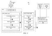
- FIG. 3 is a block diagram illustrating an omni-channel purchase history system 300, in accordance with an example embodiment.
- the omni-channel purchase history system 300 can comprise any combination of one or more of a cloud platform 310, a cloud connector 320, and a back-end system 330 (e.g., an enterprise cloud or an on-premise domain), which can reside on one or more machines, each having a memory and at least one processor (not shown).
- any combination of one or more of the components of omni-channel purchase history system 300 can be incorporated into the enterprise application platform 112 in FIG. 1 (e.g., on application server(s) 126).
- FIG. 1 e.g., on application server(s) 126.
- it is contemplated that other configurations are also within the scope of the present disclosure.
- other configurations are also within the scope of the present disclosure.
- the network(s) can include any network that enables communication between or among machines, databases, and devices. Accordingly, the network(s) can include a wired network, a wireless network (e.g., a mobile or cellular network), or any suitable combination thereof.
- the network(s) can include one or more portions that constitute a private network, a public network (e.g., the Internet), or any suitable combination thereof. Other configurations are also within the scope of the present disclosure.
- Omni-channel purchase history system 300 can be used by a consumer 302 to access purchase information comprising details of purchases made by the consumer 302 via a plurality of retail channels.
- the consumer 302 can access this information using any computing device at any time.
- the plurality of retail channels can comprise all of the available retail channels for one or more service providers.
- the retail channels comprise brick-and-mortar stores (that refer to in-store terminals) 306 and online stores 308.
- Retail channels within the brick-and-mortar stores 306 can include a variety of in-store point-of-sale terminals, including, but not limited to, in-store cashier terminals.
- Retail channels within the online stores 308 can include, but are not limited to, websites and mobile applications.
- a central repository e.g., one or more in-memory databases, such as database(s) 130 in FIG. 1 .
- the central repository can have the ability to expose this information in a particular way to consuming applications.
- the back-end system 330 in response to (or otherwise subsequent to) a purchase being made by the consumer 302 via any of the available retail channels (e.g., at one of the retail channels within (online) brick-and-mortar store(s) 306 and/or online store(s) 308), details of the purchase can be transmitted to the back-end system 330, where the details of the purchase can be stored.
- the purchase information is provided by the point of sale to the back-end system 330 in either real-time or near real-time with respect to the purchases being transacted. For example, in response to the consumer 302 purchasing a product at a point of sale in an online brick-and-mortar store 306, the details of the purchase can immediately be sent to the back-end system 300, where they can be accessed by the consumer 302.
- the back-end system 330 is dedicated to a single retail entity having a central management.
- the single retail entity can have transacted the purchases made by the consumer 302.
- the single retail entity comprises a plurality of chain stores (e.g., Target® stores).
- the back-end system 330 is part of a private network of the single retail entity, and the back-end system 330 is used by the single retail entity to manage purchase transactions and product inventory.
- the back-end system 330 can include enterprise resource planning (ERP) software used by the single retail entity to store and manage data from different stages of its business. These stages can include any combination of one or more of marketing and sales, inventory management, and payment and shipping.
- ERP enterprise resource planning
- the back-end system 330 can be used by the single retail entity to track business resources (e.g., cash, raw materials, production capacity) and the status of business commitments (e.g., orders, purchase orders, and payroll).
- business resources e.g., cash, raw materials, production capacity
- business commitments e.g., orders, purchase orders, and payroll
- the back-end system can share data across the various departments of the single retail entity (e.g., manufacturing, purchasing, sales, and accounting).
- the purchase information is made available for retrieval and presentation to the consumer on the computing device in real-time or near real-time with respect to the purchase information being stored on the back- end system 330. In some example embodiments, the purchase information is received by the back-end system 330 in real-time or near real-time with respect to completion of the corresponding purchases.
- the back-end system 330 can be dedicated to a single service provider in order to handle all the omni-channel purchase information for the single service provider.
- the back-end system 330 is configured to store all of the purchase information (e.g., all sales transactions) from all available retail channels only for a single service provider.
- the back-end system 330 can be dedicated to multiple service providers to handle all the omni-channel purchase information across the multiple service providers.
- the purchase information can be in the form of a transaction log (TLOG) or a sale order.
- TLOG can comprise a history of actions executed by a database management system.
- the purchase information can comprise sales transactions contained at the most granular level (e.g., products purchased, dates and/or times of purchases, locations of purchases, channels of purchases, promotions used or otherwise associated with purchases).
- the purchase information stored in the back-end system 330 can be associated with loyalty information.
- the loyalty information can be used to identify the consumer who completed the transaction.
- the loyalty information can be captured at the point of sale.
- the point of sale comprises the device that captures the sale, which can include, but is not limited to, a kiosk, a website, or a point of sale terminal.
- Consumers can register on a web site that is hosted on the cloud platform 310. This web site can allow the consumer to view his purchase history.
- the web site registration can be linked to the loyalty program of the corresponding service provider.
- the cloud platform enables only registered members to access the purchase information. Members can be consumers who have registered with the corresponding service provider via a loyalty program and have registered on the cloud platform. Registered consumers can be issued and provided with a password for using the services of the cloud platform disclosed herein.
- the password can be generated on the cloud platform.
- the consumer can dictate the password (e.g., enter a consumer-created password in a text field) during a registration process.
- the consumer 302 can access the cloud platform 310 via the public Internet (or some other network connection) using one or more computing devices 304.
- computing device(s) 304 can include, but is not limited to, a desktop computer, a laptop computer, a tablet computer, and a smartphone. Other types of computing devices 304 are also within the scope of the present disclosure.
- the consumer 302 on the computing device 304 can access the cloud platform 310 through a demilitarized zone (DMZ).
- DMZ is a computer or small subnetwork that sits between a trusted internal network, such as a corporate private LAN, and an untrusted external network, such as the public Internet.
- the computing device 304 can access the cloud platform 310 through a load balancer 309 that resides inside the DMZ.
- the back-end system 330 does not reside within a DMZ.
- the cloud platform 310 does not reside within a DMZ.
- the cloud platform 310 is implemented on a server residing outside of a firewall of the back-end system 330.
- the cloud platform 310 can be implemented as a multi-tenant Platform-as-a-Service (PaaS).
- PaaS Platform-as-a-Service
- the cloud platform 310 can be separated from the cloud connector 320 by a virtual private network (VPN) tunnel.
- VPN virtual private network
- the consumer 302 can use one or more user interface (UI) integration services 312 on the cloud platform 310 to request (e.g., submit a query for) purchase information corresponding to purchases made by the consumer 302.
- UI integration service(s) 312 is based on a combination of HTML5, Cascading Style Sheets (CSS), and JavaScript, and is built on one or more libraries, such as jQuery.
- the UI integration service(s) 312 comprises a UI development toolkit for HTML5 (e.g., SAPUI5).
- a user interface layer of the UI integration service(s) 312 can request data (e.g., purchase information) from a retail proxy module 314.
- the retail proxy module 314 can be configured to overcome same-origin policy issues.
- a same-origin policy restricts which network messages one origin can send to another.
- the same-origin policy permits scripts running on pages originating from the same site - a combination of scheme, hostname, and port number - to access each other's Document Object Model (DOM) with no specific restrictions, but prevents access to DOM on different sites.
- the same-origin policy restricts how the UI integration service(s) 312 code loaded from the cloud platform 310 can interact with a resource from another origin.
- the retail proxy module 314 can transfer the data request using a retail destination provided by a retail destination module 316.
- the retail destination module 316 can translate the query into the retail destination.
- the retail destination can be used for outbound communication from the cloud platform 310 to the back-end system 330 on which the requested data resides and/or from which the requested data is being retrieved.
- the retail destination can contain the connection details for the remote communication with the back-end system.
- the retail destination can be represented by a symbolic name and an identification of a virtual host, which can be used by the cloud platform 310 to securely and anonymously refer to remote connections.
- the symbolic name can be any identification (e.g., name) that uniquely represents the retail destination.
- the identification of the virtual host does not reveal anything about the back-end system.
- the identification of the virtual host can be characterized by an absence of any identification of the back- end system or its location.
- the retail destination can also comprise an identification of a service that can be invoked on the back-end system to retrieve the requested data stored on the back- end system.
- the identification of the service comprises an OData URL path, which can identify which OData service to invoke on the back-end system in order to retrieve the requested data from the back-end system.
- OData is a data access protocol.
- a retail destination can read:
- the identification of the virtual host can be "myapp.cloud” and the identification of the service can be “sap/iwbep/app1.”
- Other examples are also within the scope of the present disclosure.
- the cloud platform 310 can transfer the data request, including the retail destination, to the cloud connector 320.
- Cloud connector 320 can resolve the missing information (e.g., the identification of the internal host on which the requested data resides).
- the identification of the virtual host 322 e.g., "myapp.cloud”
- a real, concrete internal host 324 e.g., "ldci-cat.wdf.sap.corp”
- the internal host can identify the actual back-end system on which the requested data resides and/or from which the requested data is being retrieved.
- the identification of the service (e.g., "sap/iwbep/app1") can then be concatenated to the internal host (e.g., "1dcicat.wdf.sap.corp”) by a retail service URL path module 326, thereby generating a complete link (e.g., "ldci-cat.wdf.sap.corp:5000/sap/iwbep/app1 ") for the data request.
- the internal host e.g., "1dcicat.wdf.sap.corp”
- the complete link including the identification of the internal host and the identification of the service, can then be used to request the data from the back-end system 330.
- a retail service e.g., an OData service
- the back-end system 330 can then provide the requested data to the cloud connector 320, which can then relay the requested data back to the cloud platform 310, where it can be caused to be displayed to the consumer 302 on the computing device 304.
- the cloud connector 320 can act as a reverse proxy. By using a mapping of an identification of a virtual host to an identification of an internal host, the cloud connector 320 can enable the consumer 302 to access data on the back-end system 330, while preventing hackers, or any other ill-intentioned users attempting to perform a malicious trace, from accessing the data on the back-end system 330.
- the cloud connector 320 prevents anyone from accessing the data on the back-end system 330 simply by using the right username and password, as the identification of the internal host is not used, and therefore nor discoverable, within the DMZ.
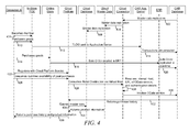
- FIG. 4 is a process flow diagram illustrating data flow operations, in accordance with some example embodiments.
- the data flow operations can be performed by processing logic that can comprise hardware (e.g., circuitry, dedicated logic, programmable logic, microcode, etc.), software (e.g., instructions run on a processing device), or a combination thereof.
- the data flow operations of FIG. 4 are performed by the omni-channel purchase history system 300 of FIG. 3 , or any combination of one or more of its components, as described above.
- Master data (e.g,, product information) can reside on a repository database.
- the repository database can reside on the cloud platform 310.
- the master data can reside on an enterprise cloud or on an on-premise domain, depending on different factors, including, but not limited to, data privacy, data volume, data type (e.g., master data, transactional data, configuration data), data update frequency, and the systems relying on the data.
- Mater data fits well on the cloud platform 310 because it does not contain private user information, its volume is rather low, the data is not updated frequently, and the cloud applications often rely heavily on this information.
- the master data can be replicated from the repository database on the back-end system 330 to a cloud database on the cloud platform 310.
- This replication can be asynchronous and permanent, meaning that the applications querying the master data no longer need to communicate with the repository database on the back-end system 330.
- consumer A can start registering.
- the first step can be completed in a physical store (e.g., brick-and-mortar store 306) using an in-store POS terminal, such as when a consumer becomes a loyalty member. This operation can be accomplished when the consumer is purchasing goods and reading information about the program.
- a physical store e.g., brick-and-mortar store 306
- an in-store POS terminal such as when a consumer becomes a loyalty member. This operation can be accomplished when the consumer is purchasing goods and reading information about the program.
- the consumer can purchase goods via an in-store POS terminal.
- the in-store POS terminal can update the transaction logs on a repository application server directly.
- the repository application server can reside on the back-end system 330.
- the repository application server can persist the data on the repository database (e.g., following a 3-tier architecture).
- ERP application server can reside on back-end system 330 and can comprise business management software (e.g., a suite of integrated applications) that a company can use to store and manage data from every stage of business.
- ERP can provide an integrated real-time view of core business processes, using common databases maintained by a database management system.
- ERP systems track business resources (e.g., cash, raw materials, production capacity) and the status of business commitments (e.g., orders, purchase orders, and payroll).
- business resources e.g., cash, raw materials, production capacity
- business commitments e.g., orders, purchase orders, and payroll
- the applications that make up the system can share data across the various departments (e.g., manufacturing, purchasing, sales, accounting, etc.) that entered the data.
- ERP can facilitate information flow between all business functions, and can manage connections to outside stakeholders.
- the ERP sale orders can be replicated in real-time, or near real-time, on the repository database. As a result, both in-store purchases and online purchases can become present on the repository database.
- the consumer can consult his purchase history.
- the consumer can register with a corresponding service on the cloud platform 310.
- the consumer can attempt to consume the real-time availability of his or her purchase information (e.g., information about past purchases).
- the consumer can log on to the cloud platform service, and query one or more past purchases in real-time (or near real-time). This data consumption can refer to both in-store (brick-and-mortar) purchases and online purchases, despite the fact that they are coming from different channels.
- the cloud platform 310 can translate the query into a retail destination, which can be used for the outbound communication of the cloud platform 310 to the back-end system 330.
- the retail destination can contain the connection details for the remote communication with the back-end system 330.
- the retail destination can be represented by a symbolic name and a virtual host, which can be used by the cloud platform 310 to securely and anonymously refer to remote connections.
- a data request, including the retail destination, can be sent to the cloud connector 320.
- the cloud connector can resolve the internal host at runtime based on the symbolic name and virtual host provided in the request, which can produce an object that contains customer-specific configuration details, such as an internal host, the URL of the remote system or service, the authentication type, and the relative credentials (e.g., username and password).
- customer-specific configuration details such as an internal host, the URL of the remote system or service, the authentication type, and the relative credentials (e.g., username and password).
- the cloud connector 430 can cause the service (e.g., an OData service) on the back-end system 330 to be invoked on the repository database in order to obtain the requested purchase information.
- the purchase information e.g., in the form of an OData signature containing the purchase history
- the cloud platform 310 can return to the cloud platform 310.
- the repository database only returns a subset of the information requested by or relevant to the consumer. For example, in some embodiments, the repository database returns a product ID, but not a complete description of the corresponding product.
- this missing information can be retrieved directly from the cloud database using the master data replicated via operations 402, 404, and 406.
- the retrieved purchase information and product information can be returned to each invoking software/protocol/server layer, where it can be displayed or otherwise presented to the consumer.
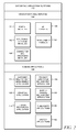
- FIG. 5 is a flowchart illustrating a method 500, in accordance with some example embodiments.
- Method 500 can be performed by processing logic that can comprise hardware (e.g., circuitry, dedicated logic, programmable logic, microcode, etc.), software (e.g., instructions run on a processing device), or a combination thereof.
- the method 500 is performed by the an omni-channel purchase history system 300 of FIG. 3 , or any combination of one or more of its components (e.g., cloud connector 320), as described above.
- purchase information of a consumer can be received.
- the purchase information can comprise information about purchases made by the consumer via a plurality of retail channels.
- the plurality of retail channels comprise a brick-and-mortar retail channel and an online retail channel.
- the purchase information can be stored in one or more databases.
- the consumer can be enabled to access the stored purchase information via a computing device.
- the purchase information is made accessible to the user in near real-time. It is contemplated that any of the other features described within the present disclosure can be incorporated into method 500.
- FIG. 6 is a flowchart illustrating a method of enabling a consumer to access the stored purchase information (e.g., as mentioned above with respect to operation 530 in FIG. 5 ), in accordance with some example embodiments.
- Method 600 can be performed by processing logic that can comprise hardware (e.g., circuitry, dedicated logic, programmable logic, microcode, etc.), software (e.g., instructions run on a processing device), or a combination thereof.
- the method 600 is performed by the omni-channel purchase history system 300 of FIG. 3 , or any combination of one or more of its modules (e.g., cloud connector 320), as described above.
- a request to access purchase information can be received.
- the purchase information can be retrieved based on the request.
- the retrieved purchase information can be caused to be displayed to the consumer on the computing device. It is contemplated that any of the other features described within the present disclosure can be incorporated into method 600.
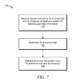
- FIG. 7 is a flowchart illustrating a method of retrieving the purchase information (e.g., as mentioned above with respect to operation 620 in FIG. 6 ), in accordance with some example embodiments.
- Method 700 can be performed by processing logic that can comprise hardware (e.g., circuitry, dedicated logic, programmable logic, microcode, etc.), software (e.g., instructions run on a processing device), or a combination thereof.
- the method 700 is performed by the omni-channel purchase history system 300 of FIG. 3 , or any combination of one or more of its modules (e.g., cloud connector 320), as described above.
- a request to access purchase information can be received.
- the request comprises an identification of a virtual host and an identification of a service to invoke on a back-end system in order to retrieve the purchase information stored on the back-end system.
- the back-end system can be associated with a service provider corresponding to the purchase information.
- an identification of an internal host can be determined. In some embodiments, the identification of the internal host is determined based on the identification of the virtual host.
- the purchase information can be retrieved using the identification of the internal host and the identification of the service.
- the identification of the service comprises an identification of an OData service on the back-end system.
- the identification of the service can comprise an OData URL path, and the purchase information can be retrieved using a concatenation of the OData URL with the identification of the internal host. It is contemplated that any of the other features described within the present disclosure can be incorporated into method 700.
- the techniques of the present disclosure enable a consumer to view his purchase history for one service provider from all available retail channels. There are many other use cases.
- a consumer can retrieve his sales history for multiple service providers on any device.
- a consumer can re-purchase items that were previously purchased.
- promotions can be targeted to the corresponding consumers based on predictive logic and previous purchases (e.g., displaying promotions to the consumer while the consumer is viewing purchase information).
- an ecosystem can be created to add new features and enhance the consumer experience when consumers interact with their sales history.
- the omni-channel purchase history system 300 can enable a consumer to find out the details of previous purchases (e.g., name of the product, make/model of purchased product, price of product, date/time of purchase, location of purchase), and then enable the consumer to perform further actions directed toward the products of the previous purchases, or their corresponding service providers, based on the details.
- a consumer can use the omni-channel purchase history system 300 to find out the details of a purchase of a pair of pants the consumer made.
- the consumer can use the omni-channel purchase history system 300 to find the original purchase transaction of the pair of pants, and then find the closest store that has the same pair of pants in inventory.
- the consumer can then use the omni-channel purchase history system 300 to reserve the pair of pants so that it can be picked up at the store by the consumer. This query and reserve use case can be applied to any products.
- the consumer can gain access to his or her purchase information (e.g., sales transactions) via the following actions.
- the consumer can register for a loyalty program with a service provider.
- the registration can be handled by the service provider.
- the consumer can be explained the features, which include access to a web site where the consumer can view his or her purchase information.
- the consumer can accept one or more loyalty licensing agreements and complete the registration for loyalty membership.
- the consumer can be sent a link to the cloud application of the cloud platform 310.
- the consumer can then log on to the cloud application using his loyalty membership credentials or e-mail credentials.
- the consumer can be prompted with a membership agreement, which authorizes the replication of the consumer's purchase information the cloud platform 310.
- a membership agreement which authorizes the replication of the consumer's purchase information the cloud platform 310.
- the purchase information for the consumer can be replicated to the cloud application from the back-end system 330 in real-time or near real-time.
- only registered loyalty members who have accepted the licensing agreement on the cloud application can have their purchase information replicated to the cloud application.
- An initial load of all purchase information can take place. Any changes to existing sales transactions by the back-end system 330 can also be replicated in real-time or near real-time.
- the replication can include all sales transactions for all channels for the consumer.
- sales are processed and replicated into back-end system 330, they can be saved in separate tables (e.g., sales transactions completed within the stores can be stored as TLOGS and sales completed in other channels can be stored as orders.
- the cloud application does not make the distinction between a TLOG and an order, but instead considers both as purchase history information.
- the extraction process from the back-end system can handle the mapping between TLOG and sales orders to purchase history information.
- the cloud application on the cloud platform 310 can be used for purchase transactions that take place within the store (e.g., brick-and-mortar) channel.
- the consumer makes a purchase within a physical store.
- the consumer is not known at this point in time, so the loyalty card can be scanned so that the consumer can accumulate points for the current transaction.
- the consumer's membership information can be determined, from which the consumer can now be identified.
- a TLOG transaction can be created and the loyalty information can be added to the TLOG file that will be sent to the back-end system 330 at the head office.
- the purchase information e.g., TLOG
- it can be replicated to cloud platform 310.
- the consumer makes a purchase at a kiosk or online. These purchases can create sales orders. At the point of order creation, the consumer can be known and identified on the order. The sales order can be created in the back-end system 330 directly. As soon as the sales order is saved or updated in an ERP, the order can be replicated to the repository database in realtime. In some embodiments, the replication can be handled by the system landscape transformation application. All sales orders can be replicated. Once the ERP sales order for the consumer is replicated to the repository database, a check can be done to confirm that this consumer has agreed to have his sales history replicated to the cloud platform 310.
- All validated orders, new or modified, can be replicated to the cloud platform 310 for members that have agreed to do so.
- the sales order details can now be available.
- the sales transactions in the repository database and ERP can be modified.
- the updated TLOG or sales orders can be reflected in the cloud platform 310.
- the repository database can automatically replicate updated sales transactions to the cloud platform 310 for registered members of the cloud application.
- the following description describes how consumers can query their sales history using the application on the cloud platform 310.
- the consumer can log onto the cloud application to view his or her transaction history.
- the consumer can use his or her loyalty membership ID or e-mail address to log on.
- the consumer can view his sales history on any computing device.
- the cloud application can allow the consumer to query his or her sales history by different characteristics (e.g., date, date range, product, category, location, price, price range).
- the cloud portal member can log on to the portal application. The consumer can then request that his membership be deactivated. A member can deactivate his or her cloud portal membership but still retain his loyalty membership. Once deactivation has been requested, all data for the cloud application can be deleted on the cloud platform 310. In some embodiments, the only data that is retained is the original document from the member, authorizing the replication of the sales history from the SAP Customer Activity Repository to the cloud platform 310, which can be retained for a corresponding legal term. Once all of the data has been deleted, an e-mail can be sent to the member. A copy of the email can be stored in the back-end system 330. The e-mail can be deleted once an appropriate legal timeframe has elapsed.
- FIG. 8 is a block diagram illustrating a mobile device 800, according to an example embodiment.
- the mobile device 800 can include a processor 802.
- the processor 802 can be any of a variety of different types of commercially available processors suitable for mobile devices 800 (for example, an XScale architecture microprocessor, a Microprocessor without Interlocked Pipeline Stages (MIPS) architecture processor, or another type of processor).
- the memory 804 can be adapted to store an operating system (OS) 806, as well as application programs 808, such as a mobile location enabled application that can provide LBSs to a user.
- OS operating system
- application programs 808 such as a mobile location enabled application that can provide LBSs to a user.
- the processor 802 can be coupled, either directly or via appropriate intermediary hardware, to a display 810 and to one or more input/output (I/O) devices 812, such as a keypad, a touch panel sensor, a microphone, and the like.
- the processor 802 can be coupled to a transceiver 814 that interfaces with an antenna 816.
- the transceiver 814 can be configured to both transmit and receive cellular network signals, wireless data signals, or other types of signals via the antenna 816, depending on the nature of the mobile device 800.
- a GPS receiver 818 can also make use of the antenna 816 to receive GPS signals.
- Modules can constitute either software modules (e.g., code embodied on a machine-readable medium or in a transmission signal) or hardware modules.
- a hardware module is a tangible unit capable of performing certain operations and can be configured or arranged in a certain manner.
- one or more computer systems e.g., a standalone, client, or server computer system
- one or more hardware modules of a computer system e.g., a processor or a group of processors
- software e.g., an application or application portion
- a hardware module can be implemented mechanically or electronically.
- a hardware module can comprise dedicated circuitry or logic that is permanently configured (e.g., as a special-purpose processor, such as a field programmable gate array (FPGA) or an application-specific integrated circuit (ASIC)) to perform certain operations.
- a hardware module can also comprise programmable logic or circuitry (e.g., as encompassed within a general-purpose processor or other programmable processor) that is temporarily configured by software to perform certain operations. It will be appreciated that the decision to implement a hardware module mechanically, in dedicated and permanently configured circuitry, or in temporarily configured circuitry (e.g., configured by software) can be driven by cost and time considerations.
- the term "hardware module” should be understood to encompass a tangible entity, be that an entity that is physically constructed, permanently configured (e.g., hardwired) or temporarily configured (e.g., programmed) to operate in a certain manner and/or to perform certain operations described herein.
- hardware modules are temporarily configured (e.g., programmed)
- each of the hardware modules need not be configured or instantiated at any one instance in time.
- the hardware modules comprise a general-purpose processor configured using software
- the general-purpose processor can be configured as respective different hardware modules at different times.
- Software can accordingly configure a processor, for example, to constitute a particular hardware module at one instance of time and to constitute a different hardware module at a different instance of time.
- Hardware modules can provide information to, and receive information from, other hardware modules. Accordingly, the described hardware modules can be regarded as being communicatively coupled. Where multiple of such hardware modules exist contemporaneously, communications can be achieved through signal transmission (e.g., over appropriate circuits and buses) that connect the hardware modules. In embodiments in which multiple hardware modules are configured or instantiated at different times, communications between such hardware modules can be achieved, for example, through the storage and retrieval of information in memory structures to which the multiple hardware modules have access. For example, one hardware module can perform an operation and store the output of that operation in a memory device to which it is communicatively coupled. A further hardware module can then, at a later time, access the memory device to retrieve and process the stored output. Hardware modules can also initiate communications with input or output devices and can operate on a resource (e.g., a collection of information).
- a resource e.g., a collection of information
- processors that are temporarily configured (e.g., by software) or permanently configured to perform the relevant operations.
- processors can constitute processor-implemented modules that operate to perform one or more operations or functions.
- the modules referred to herein can, in some example embodiments, comprise processor-implemented modules.
- the methods described herein can be at least partially processor-implemented. For example, at least some of the operations of a method can be performed by one or more processors or processor-implemented modules. The performance of certain of the operations can be distributed among the one or more processors, not only residing within a single machine, but deployed across a number of machines. In some example embodiments, the processor or processors can be located in a single location (e.g., within a home environment, an office environment or as a server farm), while in other embodiments the processors can be distributed across a number of locations.
- the one or more processors can also operate to support performance of the relevant operations in a "cloud computing" environment or as a “software as a service” (SaaS). For example, at least some of the operations can be performed by a group of computers (as examples of machines including processors), these operations being accessible via a network (e.g., the network 114 of FIG. 1 ) and via one or more appropriate interfaces (e.g., APIs).
- SaaS software as a service
- Example embodiments can be implemented in digital electronic circuitry, or in computer hardware, firmware, software, or in combinations of them.
- Example embodiments can be implemented using a computer program product, e.g., a computer program tangibly embodied in an information carrier, e.g., in a machine-readable medium for execution by, or to control the operation of, data processing apparatus, e.g., a programmable processor, a computer, or multiple computers.
- a computer program can be written in any form of programming language, including compiled or interpreted languages, and it can be deployed in any form, including as a stand-alone program or as a module, subroutine, or other unit suitable for use in a computing environment.
- a computer program can be deployed to be executed on one computer or on multiple computers at one site or distributed across multiple sites and interconnected by a communication network.
- operations can be performed by one or more programmable processors executing a computer program to perform functions by operating on input data and generating output.
- Method operations can also be performed by, and apparatus of example embodiments can be implemented as, special purpose logic circuitry (e.g., a FPGA or an ASIC).
- a computing system can include clients and servers.
- a client and server are generally remote from each other and typically interact through a communication network. The relationship of client and server arises by virtue of computer programs running on the respective computers and having a client-server relationship to each other.
- both hardware and software architectures merit consideration. Specifically, it will be appreciated that the choice of whether to implement certain functionality in permanently configured hardware (e.g., an ASIC), in temporarily configured hardware (e.g., a combination of software and a programmable processor), or a combination of permanently and temporarily configured hardware can be a design choice.
- hardware e.g., machine
- software architectures that can be deployed, in various example embodiments.
- FIG. 9 is a block diagram of a machine in the example form of a computer system 900 within which instructions 924 for causing the machine to perform any one or more of the methodologies discussed herein can be executed, in accordance with an example embodiment.
- the machine operates as a standalone device or can be connected (e.g., networked) to other machines.
- the machine can operate in the capacity of a server or a client machine in a server-client network environment, or as a peer machine in a peer-to-peer (or distributed) network environment.
- the machine can be a personal computer (PC), a tablet PC, a set-top box (STB), a Personal Digital Assistant (PDA), a cellular telephone, a web appliance, a network router, switch or bridge, or any machine capable of executing instructions (sequential or otherwise) that specify actions to be taken by that machine.
- PC personal computer
- PDA Personal Digital Assistant
- STB set-top box
- WPA Personal Digital Assistant
- a cellular telephone a web appliance
- network router switch or bridge
- machine any machine capable of executing instructions (sequential or otherwise) that specify actions to be taken by that machine.
- machine shall also be taken to include any collection of machines that individually or jointly execute a set (or multiple sets) of instructions to perform any one or more of the methodologies discussed herein.
- the example computer system 900 includes a processor 902 (e.g., a central processing unit (CPU), a graphics processing unit (GPU) or both), a main memory 904 and a static memory 906, which communicate with each other via a bus 908.
- the computer system 900 can further include a video display unit 910 (e.g., a liquid crystal display (LCD) or a cathode ray tube (CRT)).
- the computer system 900 also includes an alphanumeric input device 912 (e.g., a keyboard), a user interface (UI) navigation (or cursor control) device 914 (e.g., a mouse), a disk drive unit 916, a signal generation device 918 (e.g., a speaker) and a network interface device 920.
- an alphanumeric input device 912 e.g., a keyboard
- UI user interface
- cursor control device 914 e.g., a mouse
- disk drive unit 916 e.g., a disk drive unit 916
- signal generation device 918 e.g., a speaker
- network interface device 920 e.g., a network interface device 920.
- the disk drive unit 916 includes a machine-readable medium 922 on which is stored one or more sets of data structures and instructions 924 (e.g., software) embodying or utilized by any one or more of the methodologies or functions described herein.
- the instructions 924 can also reside, completely or at least partially, within the main memory 904 and/or within the processor 902 during execution thereof by the computer system 900, the main memory 904 and the processor 902 also constituting machine-readable media.
- the instructions 924 can also reside, completely or at least partially, within the static memory 906.
- machine-readable medium 922 is shown in an example embodiment to be a single medium, the term “machine-readable medium” can include a single medium or multiple media (e.g., a centralized or distributed database, and/or associated caches and servers) that store the one or more instructions 924 or data structures.
- the term “machine-readable medium” shall also be taken to include any tangible medium that is capable of storing, encoding or carrying instructions for execution by the machine and that cause the machine to perform any one or more of the methodologies of the present embodiments, or that is capable of storing, encoding or carrying data structures utilized by or associated with such instructions.
- the term “machine-readable medium” shall accordingly be taken to include, but not be limited to, solid-state memories, and optical and magnetic media.
- machine-readable media include non-volatile memory, including by way of example semiconductor memory devices (e.g., Erasable Programmable Read-Only Memory (EPROM), Electrically Erasable Programmable Read-Only Memory (EEPROM), and flash memory devices); magnetic disks such as internal hard disks and removable disks; magneto-optical disks; and compact disc-read-only memory (CD-ROM) and digital versatile disc (or digital video disc) read-only memory (DVD-ROM) disks.
- semiconductor memory devices e.g., Erasable Programmable Read-Only Memory (EPROM), Electrically Erasable Programmable Read-Only Memory (EEPROM), and flash memory devices
- EPROM Erasable Programmable Read-Only Memory
- EEPROM Electrically Erasable Programmable Read-Only Memory
- flash memory devices e.g., Electrically Erasable Programmable Read-Only Memory (EEPROM), and flash memory devices
- magnetic disks such as internal hard disks and removable disks
- the instructions 924 can further be transmitted or received over a communications network 926 using a transmission medium.
- the instructions 924 can be transmitted using the network interface device 920 and any one of a number of well-known transfer protocols (e.g., HTTP).
- Examples of communication networks include a LAN, a WAN, the Internet, mobile telephone networks, POTS networks, and wireless data networks (e.g., WiFi and WiMax networks).
- the term "transmission medium” shall be taken to include any intangible medium capable of storing, encoding, or carrying instructions for execution by the machine, and includes digital or analog communications signals or other intangible media to facilitate communication of such software.
- FIG. 10 is a representative view of a telecommunication system 1000 in accordance with an example of the present disclosure.
- the telecommunication system 1000 comprises a mobile telecommunication device 1001 (such as device 800 of FIG. 8 ).
- the telecommunication system 1000 further comprises electronic devices 1003A-N.
- An electronic device of the electronic devices 1003A-N may comprise a terminal, a server an automated (or automatic) vending machine, an electronic loyalty system, or an automated payment machine such as a parking meter.
- the telecommunication system 1000 further comprises a backend server 1005.
- the mobile telecommunication device 1001 stores a plurality of mobile applications 1015A-N e.g. in a memory (not shown) of the mobile telecommunication device 1001 (such as memory 804 of FIG.8 ).
- Each of the plurality of mobile applications 1015A-N comprises instructions that when executed cause a processor (e.g. 802) of the mobile telecommunication device 1001 to connect to a respective electronic device for requesting a service to the electronic device 1003A-N.
- a processor e.g. 802
- each mobile application of the plurality of mobile application 1015A-N may enable access to services provided by one or more electronic devices of the electronic devices 1003A-N.
- mobile application 1015A may comprise a web application that may be used by a user of the mobile telecommunication device 1001 (or of the mobile application 1015A) to connect via a communication channel 1013A to the electronic device 1003A being a web server in order to register with the web server.
- the electronic device 1003A-N may be adapted (when the instructions are executed) to send a response to the service request (e.g. a registration confirmation message) using at least a first user identification address assigned to the user of the mobile application. For example, for each mobile application of the plurality of mobile applications a respective first user identification address may be used to send the response to the service request performed using that mobile application.
- the first user identification address may for example be an email address or an IP address of the mobile telecommunication device 1001 of the user etc.
- the web server 1003A may send a confirmation message or an acknowledgement message indicating the subscription of the user via the communication channel 1013A.
- the confirmation message may comprise account details of the user as well as (pdf) documents e.g. guides comprising instructions on how to access and/or use services provided by the web server.
- the confirmation message may be sent for example as an email to the user of the mobile telecommunication device 1001 that may be received at the mobile telecommunication device 1001.
- the mobile application may comprise a mobile application allowing the user to purchase items from an automated vending machine 1003C e.g. via a near field communication between the mobile telecommunication device 1001 and the automated vending machine 1003C.
- Each of the electronic devices 1003A-N is connected to the backend server 1005 via at least one network 1009.
- network 1009 may comprise a local area network (LAN), a general wide area network (WAN), and/or a public network (e.g., the Internet).
- LAN local area network
- WAN wide area network
- Internet public network
- the mobile telecommunication system 1000 further comprises a DMZ interface 1007 (e.g. DMZ of FIG. 3 ) between the back-end server 1005 and the network 1011 that connects the mobile telecommunication device 1001 to the back-end server 1005.
- a DMZ interface is a computer or small subnetwork that sits or is inserted between a network e.g. a private network such as a corporate private LAN (that comprises the backend server 1005), and an untrusted external network, such as the public Internet.
- the DMZ interface 1007 may prevent outside users such as the mobile telecommunication device 1001 from getting direct access to the back-end server 1005.
- the DMZ interface 1007 may include a web server or service and (optionally) one or more firewalls.
- Firewalls provide security for DMZ.
- Web server of the DMZ interface 1007 may receive users' requests and process these requests by forwarding them (e.g. via a firewall of the one or more firewalls or directly) to the back-end server 1005.
- the DMZ interface 1007 may act as a proxy server.
- the mobile telecommunication device 1001 can access only the DMZ interface 1007.
- At least part of the telecommunication system 1000 may be provided as part of a cloud computing environment that enables users to use compute resources such as the backend server 1005 including the DMZ interface 1007 and the electronic devices 1003A-N as a utility (the DMZ interface 1007 may be part of the cloud connector 320 as described above).
- the cloud computing environment may provide the backend server 1005 as part of the cloud computing and the present method as a utility service e.g. allowing for example to send data by the electronic devices 1003A-N and to store them at the backend server etc.
- the at least part of the telecommunication system 1000 may be provided as in-memory Platform-as- ⁇ -Service.
- the provider's computing resources are pooled to serve multiple users using a multi-tenant model, with different physical and virtual resources dynamically assigned and reassigned according to consumer demand.
- FIG. 11 is a flowchart of a method for securing data access to the telecommunication system 1000.
- a second identification address may be assigned to the backend server 1005.
- the second identification address defines a network connection of the second network 1009 to the backend server 1005 (e.g. the second identification address may be a destination address that may be used by an electronic device 1003A in order to send data to the backend server 1005 via the network connection which refers to a connection between the electronic device 1003A and the backend server 1005 that is initiated or established over the second network).
- the network connection may be a trusted network connection such as a secure HTTP connection.
- the second identification address may comprise an IP address of the backend server 1005 or an FTP address.
- the communication between the backend server 1005 and each of the electronic devices 1003A-N may use a cryptographic protocol such as Transport Layer Security (TLS) and Secure Sockets Layer (SSL).
- TLS Transport Layer Security
- SSL Secure Sockets Layer
- the mobile telecommunication device 1001 may receive from the user a service request.
- the service request may comprise for example a query for an operational status of the electronic device 1003A-N e.g. the number of services satisfied or the number of times the electronic device 1003A-N has been used to provide a given service at a given time interval for the user.
- the service request may comprise a request to upload an electronic document such as a picture to the electronic device 1003A, wherein the electronic device may comprise a web server that hosts that electronic document.
- the service request may comprise a request to purchase items from an automated vending machine of the electronic devices 1003A-N.
- the user may launch the mobile application by clicking on an icon that represents the mobile application and that is displayed on a display of the mobile telecommunication device 1001.
- the instructions of the mobile application may be executed by for example displaying on the display of the mobile telecommunication device 1001 a graphical user interface that may indicate using user interface elements services provided by an electronic device of the electronic devices 1003A-N.
- a mobile application 1015B may comprise a payment application for paying using the mobile telecommunication device 1001 at a payment machine e.g. 1003B.
- user interface element may be understood as a user interface object, or a set of user interface objects, displayed on a display screen of a device.
- a user interface element comprises a button, a text box, a tab, an icon, a text field, a pane, a check-box item, a menu bar, a title bar, an action bar or item group or the like.
- a user interface element may likewise be an image, a displayed alphanumeric character or any combination thereof.
- graphical user interface or "user interface” as used herein refers to an interface generated by a program for display on a display screen of a device with selectable user interface elements.
- server refers to a computer hardware and/or software that communicates with other electronic devices through a network.
- the server may comprise a computer server such as a web server.
- terminal encompasses a device that is capable of establishing a communication link with a second device for transmitting, receiving or exchanging information with that second device.
- the terminal may comprise a payment device.
- the terminal may comprise an access control terminal that controls access to a given area.
- the terminal may receive a service request from the user of the mobile telecommunication device for accessing the area and may send an unlock signal to an automatic door opening and closing system for enabling (e.g. an automatic door opens) the user of the mobile telecommunication device to access or enter the area e.g. building that can only be accessed via the automatic door.
- the service request may be automatically sent to the terminal by for example "swiping,” “tapping,” “bumping” or otherwise moving the mobile telecommunication device in close proximity to the terminal being an NFC enabled device.
- the mobile telecommunication device may use a built-in NFC reader or writer of the mobile telecommunication device to transmit the service request to (a NFC tag of) the terminal as soon as the terminal (e.g. the NFC tag) is detected within e.g. the 10-centimeter read or access range.
- the mobile telecommunication device 1001 may establish in step 1103 a communication channel to the electronic device 1003A-N (that corresponds to the mobile application i.e. that provides requested service) for forwarding the service request by the mobile telecommunication device 1001.
- the communication channel established may be performed using a short-range wireless technology such as near field communication (NFC).
- NFC near field communication
- the mobile telecommunication device 1001 and at least part of the electronic devices 1003A-N are NFC-enabled devices.
- the distance of the mobile telecommunication device 1001 and the electronic device 1003A-N is 10 cm or less.
- the communication channel may comprise an NFC peer-to-peer communication channel.
- the mobile telecommunication device 1001 and the electronic devices 1003A-N may communicate via a network that may comprise a LAN, a general WAN, and/or a public network (e.g., the Internet).
- the mobile telecommunication device 1001 and the electronic devices 1003A-N may communicate via Bluetooth, Zigbee in order to communicate the service request and other data.
- the electronic device 1003A-N may process the service request.
- the electronic device 1003A-N may store the electronic document received from the user (the mobile telecommunication device 1001).
- the electronic device 1003A-N being the automated vending machine may provide the purchased item.
- the electronic device redirects (sends) to the backend server 1005 the response to the service request by using the second identification address instead of the first user identification address.
- the electronic device 1003A-N (being the automated vending machine) may send the response indicating details of the purchase such as the time at which the purchase has been made, an electronic document describing the purchased item etc.
- the electronic device 1003A-N may generate a cryptographic key pair comprising a public encrypting key and a private encrypting key.
- the response may be encrypted by the electronic device 1003A-N using the public encrypting key in order to generate encrypted data.
- the encrypted data may then be sent together with both keys to the backend server 1005 by the electronic device 1003A-N.
- the electronic device 1003A-N may in addition send the private decryption key to the mobile telecommunication device 1001.
- only one of the electronic devices 1003A-N may send a private decryption key to the mobile telecommunication device 1001. This may save storage resources in the mobile telecommunication device 1001 in particular when the submitted private decryption key is used for authenticating the mobile telecommunication device 1001 at the backend server 1005 as described below.
- the backend server 1005 may store response data comprising the received responses in association with a user ID of the user.
- the backend server 1005 may receive a plurality of responses that corresponds to the respective plurality of service requests that have been performed or received at the respective plurality of mobile applications 1015A-N.
- a common storage place is provided for data of the user. This may facilitate access to data, and save processing resources such as data traffic may be reduced in the telecommunication system, because otherwise the user has to connect to each electronic device that has provided a service in order to get his or her data. For example, this may also avoid storing response data in the mobile telecommunication device as the mobile telecommunication device 1001 may not have enough storage space and enough processing resources to save and to process the response data locally.
- the backend server 1005 may generate a web service 1017 for providing the response data via an URL.
- a Web service may provide a method of communication between two electronic devices over a network.
- the web service may comprise a software system (e.g. a code implementing an XML interface for accessing a given set of data at the backend server 1005) designed to support interoperable machine-to-machine interaction over a network.
- the web service may be generated at once (for the user of the mobile telecommunication device) and thereafter the web service may receive one or more data access requests from the user of the mobile telecommunication device to access at least the given data set.
- the web service may be dynamically generated as soon as new responses or data is received from an electronic device at the backend server such that the web service may enable the access to the newly received data via the DMZ interface in addition to the given data set.
- the response data that are accessible via the URL may only comprise data related to or of the user of the mobile telecommunication device 1001.
- the web service 1017 is placed in the DMZ interface 1007 in step 1113.
- a server may provide storage or a web service to another computing device.
- the DMZ interface 1007 may have web pages (and the response data of the user of the mobile telecommunication device 1001) provided by the web service 1017 so these (web pages and the response data) could be served to the outside e.g. to the mobile telecommunication device 1001.
- the DMZ interface 1007 does not provide the user of the mobile telecommunication device 1001 access to other data on the backend server 1005 such as the response data of other users. With this limited data access method, other users data may be protected.
- the web service becomes inoperative after a predetermined duration. This may enhance the secure aspect of the present method.
- the mobile telecommunication device 1001 may be able to retrieve or access the response data only for the predetermined duration. After this, the URL becomes inoperative and the mobile telecommunication device 1001 may no longer retrieve or access the response data. This may provide more security that the response data will not be stolen.
- the backend server 1005 may receive from the mobile telecommunication device 1001 a data access request to access at least part of the stored response data.
- the data access request is indicative of the user ID.
- the mobile telecommunication device 1001 may generate a signature using the private decryption key and the data access request may further indicate that signature.
- the data access request may comprise an identification of a virtual host (e.g. backend server) and an identification of a service (e.g. web service) to invoke on a back-end system to retrieve the response data.
- the backend server 1005 may authenticate the mobile telecommunication device 1001 using the user ID. For example, the backend server 1005 may check if the user ID is comprised in a list of authorized users that is stored in the backend server 1005. In another example, the backend server 1005 may additionally or alternatively authenticate the mobile telecommunication device 1001 using the signature. The backend server 100 may verify that signature (using the corresponding public encrypting key) in order to authenticate the mobile telecommunication device 1001. This may increase the secure aspect of the present method in that an authentication based on two input values is more secure than an authentication based on a single input value.
- the backend server 1005 may send in step 1119 the URL to the mobile telecommunication device 1001.
- the URL may be inactive after a predetermined duration or time period such that the user cannot access the response data after that duration using the URL.
- the mobile telecommunication device may access the web service 1017 at the URL for requesting the at least part of the response data from the backend server 1005 (or the mobile telecommunication de 1001 may request the at least part of the response data using the URL of the web service).
- the URL may allow access to only the at least part of the response data but not the whole response data.
- the backend server 1005 may receive the data access request of the at least part of the response data via the DMZ interface 1007.
- a Firewall of the DMZ interface 1007 may particularly be relevant in DMZ implementation, since it is responsible for ensuring that proper policies are in place to protect local networks from the DMZ interface 1007, while maintaining accessibility to the DMZ interface 1007.
- the backend server 1005 may send result data indicative of the at least part of the response data to the mobile telecommunication device 1001.
- the result data may comprise the at least part of the response data.
- the result data may result from the processing of the at least part of the response data by the backend server 1005.
- the processing may, for example, be performed using the data access request for generating the result data.
- the at least part of the result data may be filtered such that the result data comprises at least one of: data received from electronic devices having a geographical location that matches the position of the mobile telecommunication device; data being received within a predefined time interval; data received from electronic devices being trusted systems.
- a trusted system is a system that supports Trusted Computer Group (TCG) security specifications.
- the backend server 1005 may comprise or receive an indication of the electronic devices indicating that the electronic device is a trusted system or not.
- the backend server 1005 may process the at least part of the result data to select data that is received from the electronic devices that are in a distance to the mobile telecommunication device 1001 smaller than a predetermined maximum distance threshold (e.g. 1 km).
- a predetermined maximum distance threshold e.g. 1 km.
- the backend server 1005 may process the at least part of the result data to select data that is received within a given time period e.g. from 2014 to 2015.
- the method to process or analyze the response data may be based on a service level agreement, SLA, wherein a SLA planning and fulfillment provides pre-arrangement for, and procurement of, cloud computing resources for which a future requirement is anticipated in accordance with an SLA.
- SLA may comprise, for example, conditions on the data to be presented to the user such as the conditions on the time period or the geographical location of the electronic devices as described above.
Landscapes
- Business, Economics & Management (AREA)
- Engineering & Computer Science (AREA)
- Accounting & Taxation (AREA)
- Finance (AREA)
- Physics & Mathematics (AREA)
- Theoretical Computer Science (AREA)
- General Physics & Mathematics (AREA)
- Strategic Management (AREA)
- General Business, Economics & Management (AREA)
- Development Economics (AREA)
- Technology Law (AREA)
- Marketing (AREA)
- Economics (AREA)
- Computer Networks & Wireless Communication (AREA)
- Cash Registers Or Receiving Machines (AREA)
- Information Transfer Between Computers (AREA)
- Management, Administration, Business Operations System, And Electronic Commerce (AREA)
- Control Of Vending Devices And Auxiliary Devices For Vending Devices (AREA)
Applications Claiming Priority (1)
| Application Number | Priority Date | Filing Date | Title |
|---|---|---|---|
| US14/218,268 US9672572B2 (en) | 2014-03-18 | 2014-03-18 | Real-time availability of omni-channel sales data |
Publications (3)
| Publication Number | Publication Date |
|---|---|
| EP2922013A2 true EP2922013A2 (de) | 2015-09-23 |
| EP2922013A3 EP2922013A3 (de) | 2015-09-30 |
| EP2922013B1 EP2922013B1 (de) | 2016-07-06 |
Family
ID=52987865
Family Applications (1)
| Application Number | Title | Priority Date | Filing Date |
|---|---|---|---|
| EP15159470.2A Active EP2922013B1 (de) | 2014-03-18 | 2015-03-17 | Kommunikationsverfahren für sicheren zugriff auf benutzerdaten |
Country Status (2)
| Country | Link |
|---|---|
| US (1) | US9672572B2 (de) |
| EP (1) | EP2922013B1 (de) |
Cited By (1)
| Publication number | Priority date | Publication date | Assignee | Title |
|---|---|---|---|---|
| US20170237722A1 (en) * | 2016-02-15 | 2017-08-17 | Sap Se | Networked score communications system |
Families Citing this family (6)
| Publication number | Priority date | Publication date | Assignee | Title |
|---|---|---|---|---|
| US10592476B2 (en) * | 2015-10-19 | 2020-03-17 | HomeAway.com, Inc. | Enabling clients to expose secured files via virtual hosts |
| US20170346770A1 (en) * | 2016-05-25 | 2017-11-30 | Teledini LLC | Link-invoked omni-channel chat, voice and video |
| EP3491512A4 (de) * | 2016-07-29 | 2019-06-26 | Hammel, Benjamin | Verwaltungstechniken integrierter berechtigungsnachweisdaten |
| US11055972B2 (en) * | 2017-01-16 | 2021-07-06 | Ncr Corporation | Self-service terminal (SST) network real-time cloud management |
| KR20180119854A (ko) * | 2017-04-26 | 2018-11-05 | 한국전자통신연구원 | 옴니채널 관리 장치 및 방법 |
| ES2965673T3 (es) * | 2017-04-28 | 2024-04-16 | Aptos Llc | Sistemas y procedimientos de sincronización de datos de punto de venta |
Family Cites Families (11)
| Publication number | Priority date | Publication date | Assignee | Title |
|---|---|---|---|---|
| US8117298B1 (en) * | 1996-02-26 | 2012-02-14 | Graphon Corporation | Multi-homed web server |
| US20040078371A1 (en) * | 2002-05-22 | 2004-04-22 | Joel Worrall | Method and system for providing multiple virtual portals on a computer network |
| US8566239B2 (en) | 2007-02-22 | 2013-10-22 | First Data Corporation | Mobile commerce systems and methods |
| US8886714B2 (en) * | 2011-08-08 | 2014-11-11 | Ctera Networks Ltd. | Remote access service for cloud-enabled network devices |
| US20130332319A1 (en) * | 2010-09-17 | 2013-12-12 | Thomas Zuber | System and method for purchased enabled profiles |
| US20120179779A1 (en) * | 2011-01-12 | 2012-07-12 | Dolphin Enterprise Solutions Corporation d/b/a Dolphin | System and method for data storage and retrieval |
| US20120215584A1 (en) * | 2011-02-18 | 2012-08-23 | Leapset, Inc. | Tracking off-line commerce and online activity |
| US20130325612A1 (en) * | 2012-06-04 | 2013-12-05 | WebLinc LLC | Methods and systems for interfacing e-commerce platforms with brick and mortar presences |
| US9524147B2 (en) * | 2013-05-10 | 2016-12-20 | Sap Se | Entity-based cross-application navigation |
| US9165031B2 (en) * | 2013-06-13 | 2015-10-20 | Microsoft Technology Licensing, Llc | Retrieving stored data using a web service |
| US20150006732A1 (en) * | 2013-06-28 | 2015-01-01 | Sap Ag | Generic exposure of enterprise resource planning data using a cloud-based, on-demand service |
-
2014
- 2014-03-18 US US14/218,268 patent/US9672572B2/en active Active
-
2015
- 2015-03-17 EP EP15159470.2A patent/EP2922013B1/de active Active
Non-Patent Citations (1)
| Title |
|---|
| None |
Cited By (2)
| Publication number | Priority date | Publication date | Assignee | Title |
|---|---|---|---|---|
| US20170237722A1 (en) * | 2016-02-15 | 2017-08-17 | Sap Se | Networked score communications system |
| US9807076B2 (en) * | 2016-02-15 | 2017-10-31 | Sap Se | Networked score communications system |
Also Published As
| Publication number | Publication date |
|---|---|
| US20150269683A1 (en) | 2015-09-24 |
| US9672572B2 (en) | 2017-06-06 |
| EP2922013A3 (de) | 2015-09-30 |
| EP2922013B1 (de) | 2016-07-06 |
Similar Documents
| Publication | Publication Date | Title |
|---|---|---|
| US12423696B2 (en) | Transaction authorization process using blockchain | |
| US11810167B2 (en) | Item level data aggregation | |
| US11599848B2 (en) | System and method for remote management of sale transaction data | |
| US11403684B2 (en) | System, manufacture, and method for performing transactions similar to previous transactions | |
| EP2922013B1 (de) | Kommunikationsverfahren für sicheren zugriff auf benutzerdaten | |
| US11902272B1 (en) | Online security center | |
| US10679206B2 (en) | Localized identifier broadcasts to alert users of available processes and retrieve online server data | |
| JP7104184B2 (ja) | リモートemv支払いアプリケーション | |
| US20110307381A1 (en) | Methods and systems for third party authentication and fraud detection for a payment transaction | |
| US20150081534A1 (en) | Completion of online payment forms and recurring payments by a payment provider systems and methods | |
| US12236446B2 (en) | Automated transactional offers using a browser extension | |
| US20220351156A1 (en) | Systems and methods for authentication using existing credential | |
| US11829900B2 (en) | System and method for remote management of sale transaction data | |
| US20160225065A1 (en) | Universal business procurement | |
| US11941623B2 (en) | Device manager to control data tracking on computing devices | |
| US20140006261A1 (en) | Systems and methods for conducting a quick transaction | |
| US20250371515A1 (en) | Anonymity-enabled transmission of notifications without exchanging contact identifiers | |
| NEELAKANTAM et al. | METHOD, SYSTEM, AND COMPUTER PROGRAM PRODUCT FOR DISPUTE RESOLUTION USING CUSTOMIZED BATCH FILES | |
| HK40030452B (zh) | 用於忠诚度积分分配的系统和方法 |
Legal Events
| Date | Code | Title | Description |
|---|---|---|---|
| PUAL | Search report despatched |
Free format text: ORIGINAL CODE: 0009013 |
|
| PUAI | Public reference made under article 153(3) epc to a published international application that has entered the european phase |
Free format text: ORIGINAL CODE: 0009012 |
|
| AK | Designated contracting states |
Kind code of ref document: A2 Designated state(s): AL AT BE BG CH CY CZ DE DK EE ES FI FR GB GR HR HU IE IS IT LI LT LU LV MC MK MT NL NO PL PT RO RS SE SI SK SM TR |
|
| AX | Request for extension of the european patent |
Extension state: BA ME |
|
| AK | Designated contracting states |
Kind code of ref document: A3 Designated state(s): AL AT BE BG CH CY CZ DE DK EE ES FI FR GB GR HR HU IE IS IT LI LT LU LV MC MK MT NL NO PL PT RO RS SE SI SK SM TR |
|
| AX | Request for extension of the european patent |
Extension state: BA ME |
|
| RIC1 | Information provided on ipc code assigned before grant |
Ipc: G06Q 20/32 20120101ALI20150827BHEP Ipc: H04L 29/06 20060101ALI20150827BHEP Ipc: G06Q 40/00 20120101AFI20150827BHEP |
|
| 17P | Request for examination filed |
Effective date: 20160121 |
|
| RBV | Designated contracting states (corrected) |
Designated state(s): AL AT BE BG CH CY CZ DE DK EE ES FI FR GB GR HR HU IE IS IT LI LT LU LV MC MK MT NL NO PL PT RO RS SE SI SK SM TR |
|
| GRAP | Despatch of communication of intention to grant a patent |
Free format text: ORIGINAL CODE: EPIDOSNIGR1 |
|
| RIC1 | Information provided on ipc code assigned before grant |
Ipc: G06Q 40/00 20120101AFI20160224BHEP Ipc: H04L 29/06 20060101ALI20160224BHEP Ipc: G06Q 20/32 20120101ALI20160224BHEP |
|
| INTG | Intention to grant announced |
Effective date: 20160329 |
|
| GRAS | Grant fee paid |
Free format text: ORIGINAL CODE: EPIDOSNIGR3 |
|
| GRAA | (expected) grant |
Free format text: ORIGINAL CODE: 0009210 |
|
| AK | Designated contracting states |
Kind code of ref document: B1 Designated state(s): AL AT BE BG CH CY CZ DE DK EE ES FI FR GB GR HR HU IE IS IT LI LT LU LV MC MK MT NL NO PL PT RO RS SE SI SK SM TR |
|
| REG | Reference to a national code |
Ref country code: GB Ref legal event code: FG4D |
|
| REG | Reference to a national code |
Ref country code: AT Ref legal event code: REF Ref document number: 811185 Country of ref document: AT Kind code of ref document: T Effective date: 20160715 Ref country code: CH Ref legal event code: EP |
|
| REG | Reference to a national code |
Ref country code: IE Ref legal event code: FG4D |
|
| REG | Reference to a national code |
Ref country code: DE Ref legal event code: R096 Ref document number: 602015000106 Country of ref document: DE |
|
| REG | Reference to a national code |
Ref country code: NL Ref legal event code: MP Effective date: 20160706 |
|
| REG | Reference to a national code |
Ref country code: LT Ref legal event code: MG4D |
|
| REG | Reference to a national code |
Ref country code: AT Ref legal event code: MK05 Ref document number: 811185 Country of ref document: AT Kind code of ref document: T Effective date: 20160706 |
|
| PG25 | Lapsed in a contracting state [announced via postgrant information from national office to epo] |
Ref country code: FI Free format text: LAPSE BECAUSE OF FAILURE TO SUBMIT A TRANSLATION OF THE DESCRIPTION OR TO PAY THE FEE WITHIN THE PRESCRIBED TIME-LIMIT Effective date: 20160706 Ref country code: LT Free format text: LAPSE BECAUSE OF FAILURE TO SUBMIT A TRANSLATION OF THE DESCRIPTION OR TO PAY THE FEE WITHIN THE PRESCRIBED TIME-LIMIT Effective date: 20160706 Ref country code: RS Free format text: LAPSE BECAUSE OF FAILURE TO SUBMIT A TRANSLATION OF THE DESCRIPTION OR TO PAY THE FEE WITHIN THE PRESCRIBED TIME-LIMIT Effective date: 20160706 Ref country code: IT Free format text: LAPSE BECAUSE OF FAILURE TO SUBMIT A TRANSLATION OF THE DESCRIPTION OR TO PAY THE FEE WITHIN THE PRESCRIBED TIME-LIMIT Effective date: 20160706 Ref country code: IS Free format text: LAPSE BECAUSE OF FAILURE TO SUBMIT A TRANSLATION OF THE DESCRIPTION OR TO PAY THE FEE WITHIN THE PRESCRIBED TIME-LIMIT Effective date: 20161106 Ref country code: NL Free format text: LAPSE BECAUSE OF FAILURE TO SUBMIT A TRANSLATION OF THE DESCRIPTION OR TO PAY THE FEE WITHIN THE PRESCRIBED TIME-LIMIT Effective date: 20160706 Ref country code: NO Free format text: LAPSE BECAUSE OF FAILURE TO SUBMIT A TRANSLATION OF THE DESCRIPTION OR TO PAY THE FEE WITHIN THE PRESCRIBED TIME-LIMIT Effective date: 20161006 Ref country code: HR Free format text: LAPSE BECAUSE OF FAILURE TO SUBMIT A TRANSLATION OF THE DESCRIPTION OR TO PAY THE FEE WITHIN THE PRESCRIBED TIME-LIMIT Effective date: 20160706 |
|
| PG25 | Lapsed in a contracting state [announced via postgrant information from national office to epo] |
Ref country code: LV Free format text: LAPSE BECAUSE OF FAILURE TO SUBMIT A TRANSLATION OF THE DESCRIPTION OR TO PAY THE FEE WITHIN THE PRESCRIBED TIME-LIMIT Effective date: 20160706 Ref country code: ES Free format text: LAPSE BECAUSE OF FAILURE TO SUBMIT A TRANSLATION OF THE DESCRIPTION OR TO PAY THE FEE WITHIN THE PRESCRIBED TIME-LIMIT Effective date: 20160706 Ref country code: PT Free format text: LAPSE BECAUSE OF FAILURE TO SUBMIT A TRANSLATION OF THE DESCRIPTION OR TO PAY THE FEE WITHIN THE PRESCRIBED TIME-LIMIT Effective date: 20161107 Ref country code: AT Free format text: LAPSE BECAUSE OF FAILURE TO SUBMIT A TRANSLATION OF THE DESCRIPTION OR TO PAY THE FEE WITHIN THE PRESCRIBED TIME-LIMIT Effective date: 20160706 Ref country code: GR Free format text: LAPSE BECAUSE OF FAILURE TO SUBMIT A TRANSLATION OF THE DESCRIPTION OR TO PAY THE FEE WITHIN THE PRESCRIBED TIME-LIMIT Effective date: 20161007 Ref country code: PL Free format text: LAPSE BECAUSE OF FAILURE TO SUBMIT A TRANSLATION OF THE DESCRIPTION OR TO PAY THE FEE WITHIN THE PRESCRIBED TIME-LIMIT Effective date: 20160706 Ref country code: BE Free format text: LAPSE BECAUSE OF FAILURE TO SUBMIT A TRANSLATION OF THE DESCRIPTION OR TO PAY THE FEE WITHIN THE PRESCRIBED TIME-LIMIT Effective date: 20160706 Ref country code: SE Free format text: LAPSE BECAUSE OF FAILURE TO SUBMIT A TRANSLATION OF THE DESCRIPTION OR TO PAY THE FEE WITHIN THE PRESCRIBED TIME-LIMIT Effective date: 20160706 |
|
| REG | Reference to a national code |
Ref country code: FR Ref legal event code: PLFP Year of fee payment: 3 |
|
| REG | Reference to a national code |
Ref country code: DE Ref legal event code: R097 Ref document number: 602015000106 Country of ref document: DE |
|
| PG25 | Lapsed in a contracting state [announced via postgrant information from national office to epo] |
Ref country code: RO Free format text: LAPSE BECAUSE OF FAILURE TO SUBMIT A TRANSLATION OF THE DESCRIPTION OR TO PAY THE FEE WITHIN THE PRESCRIBED TIME-LIMIT Effective date: 20160706 Ref country code: EE Free format text: LAPSE BECAUSE OF FAILURE TO SUBMIT A TRANSLATION OF THE DESCRIPTION OR TO PAY THE FEE WITHIN THE PRESCRIBED TIME-LIMIT Effective date: 20160706 |
|
| PLBE | No opposition filed within time limit |
Free format text: ORIGINAL CODE: 0009261 |
|
| STAA | Information on the status of an ep patent application or granted ep patent |
Free format text: STATUS: NO OPPOSITION FILED WITHIN TIME LIMIT |
|
| PG25 | Lapsed in a contracting state [announced via postgrant information from national office to epo] |
Ref country code: SM Free format text: LAPSE BECAUSE OF FAILURE TO SUBMIT A TRANSLATION OF THE DESCRIPTION OR TO PAY THE FEE WITHIN THE PRESCRIBED TIME-LIMIT Effective date: 20160706 Ref country code: CZ Free format text: LAPSE BECAUSE OF FAILURE TO SUBMIT A TRANSLATION OF THE DESCRIPTION OR TO PAY THE FEE WITHIN THE PRESCRIBED TIME-LIMIT Effective date: 20160706 Ref country code: DK Free format text: LAPSE BECAUSE OF FAILURE TO SUBMIT A TRANSLATION OF THE DESCRIPTION OR TO PAY THE FEE WITHIN THE PRESCRIBED TIME-LIMIT Effective date: 20160706 Ref country code: SK Free format text: LAPSE BECAUSE OF FAILURE TO SUBMIT A TRANSLATION OF THE DESCRIPTION OR TO PAY THE FEE WITHIN THE PRESCRIBED TIME-LIMIT Effective date: 20160706 Ref country code: BG Free format text: LAPSE BECAUSE OF FAILURE TO SUBMIT A TRANSLATION OF THE DESCRIPTION OR TO PAY THE FEE WITHIN THE PRESCRIBED TIME-LIMIT Effective date: 20161006 |
|
| 26N | No opposition filed |
Effective date: 20170407 |
|
| PG25 | Lapsed in a contracting state [announced via postgrant information from national office to epo] |
Ref country code: SI Free format text: LAPSE BECAUSE OF FAILURE TO SUBMIT A TRANSLATION OF THE DESCRIPTION OR TO PAY THE FEE WITHIN THE PRESCRIBED TIME-LIMIT Effective date: 20160706 |
|
| PG25 | Lapsed in a contracting state [announced via postgrant information from national office to epo] |
Ref country code: MC Free format text: LAPSE BECAUSE OF FAILURE TO SUBMIT A TRANSLATION OF THE DESCRIPTION OR TO PAY THE FEE WITHIN THE PRESCRIBED TIME-LIMIT Effective date: 20160706 |
|
| REG | Reference to a national code |
Ref country code: IE Ref legal event code: MM4A |
|
| PG25 | Lapsed in a contracting state [announced via postgrant information from national office to epo] |
Ref country code: LU Free format text: LAPSE BECAUSE OF NON-PAYMENT OF DUE FEES Effective date: 20170317 |
|
| PG25 | Lapsed in a contracting state [announced via postgrant information from national office to epo] |
Ref country code: IE Free format text: LAPSE BECAUSE OF NON-PAYMENT OF DUE FEES Effective date: 20170317 |
|
| REG | Reference to a national code |
Ref country code: FR Ref legal event code: PLFP Year of fee payment: 4 |
|
| PG25 | Lapsed in a contracting state [announced via postgrant information from national office to epo] |
Ref country code: MT Free format text: LAPSE BECAUSE OF NON-PAYMENT OF DUE FEES Effective date: 20170317 |
|
| PG25 | Lapsed in a contracting state [announced via postgrant information from national office to epo] |
Ref country code: AL Free format text: LAPSE BECAUSE OF FAILURE TO SUBMIT A TRANSLATION OF THE DESCRIPTION OR TO PAY THE FEE WITHIN THE PRESCRIBED TIME-LIMIT Effective date: 20160706 |
|
| REG | Reference to a national code |
Ref country code: CH Ref legal event code: PL |
|
| PG25 | Lapsed in a contracting state [announced via postgrant information from national office to epo] |
Ref country code: LI Free format text: LAPSE BECAUSE OF NON-PAYMENT OF DUE FEES Effective date: 20180331 Ref country code: CH Free format text: LAPSE BECAUSE OF NON-PAYMENT OF DUE FEES Effective date: 20180331 |
|
| PG25 | Lapsed in a contracting state [announced via postgrant information from national office to epo] |
Ref country code: HU Free format text: LAPSE BECAUSE OF FAILURE TO SUBMIT A TRANSLATION OF THE DESCRIPTION OR TO PAY THE FEE WITHIN THE PRESCRIBED TIME-LIMIT; INVALID AB INITIO Effective date: 20150317 |
|
| PG25 | Lapsed in a contracting state [announced via postgrant information from national office to epo] |
Ref country code: CY Free format text: LAPSE BECAUSE OF FAILURE TO SUBMIT A TRANSLATION OF THE DESCRIPTION OR TO PAY THE FEE WITHIN THE PRESCRIBED TIME-LIMIT Effective date: 20160706 |
|
| PG25 | Lapsed in a contracting state [announced via postgrant information from national office to epo] |
Ref country code: MK Free format text: LAPSE BECAUSE OF FAILURE TO SUBMIT A TRANSLATION OF THE DESCRIPTION OR TO PAY THE FEE WITHIN THE PRESCRIBED TIME-LIMIT Effective date: 20160706 |
|
| PG25 | Lapsed in a contracting state [announced via postgrant information from national office to epo] |
Ref country code: TR Free format text: LAPSE BECAUSE OF FAILURE TO SUBMIT A TRANSLATION OF THE DESCRIPTION OR TO PAY THE FEE WITHIN THE PRESCRIBED TIME-LIMIT Effective date: 20160706 |
|
| PGFP | Annual fee paid to national office [announced via postgrant information from national office to epo] |
Ref country code: GB Payment date: 20260324 Year of fee payment: 12 |
|
| PGFP | Annual fee paid to national office [announced via postgrant information from national office to epo] |
Ref country code: DE Payment date: 20260319 Year of fee payment: 12 |
|
| PGFP | Annual fee paid to national office [announced via postgrant information from national office to epo] |
Ref country code: FR Payment date: 20260320 Year of fee payment: 12 |