EP2922039A2 - Système lumineux de secours et procédé correspondant - Google Patents
Système lumineux de secours et procédé correspondant Download PDFInfo
- Publication number
- EP2922039A2 EP2922039A2 EP15000735.9A EP15000735A EP2922039A2 EP 2922039 A2 EP2922039 A2 EP 2922039A2 EP 15000735 A EP15000735 A EP 15000735A EP 2922039 A2 EP2922039 A2 EP 2922039A2
- Authority
- EP
- European Patent Office
- Prior art keywords
- receiving device
- transmitting station
- lighting system
- building
- emergency lighting
- Prior art date
- Legal status (The legal status is an assumption and is not a legal conclusion. Google has not performed a legal analysis and makes no representation as to the accuracy of the status listed.)
- Granted
Links
Images

Classifications
-
- G—PHYSICS
- G08—SIGNALLING
- G08B—SIGNALLING SYSTEMS, e.g. PERSONAL CALLING SYSTEMS; ORDER TELEGRAPHS; ALARM SYSTEMS
- G08B7/00—Signalling systems according to two or more of groups G08B3/00 - G08B6/00
- G08B7/06—Signalling systems according to two or more of groups G08B3/00 - G08B6/00 using electric transmission, e.g. involving audible and visible signalling through the use of sound and light sources
- G08B7/066—Signalling systems according to two or more of groups G08B3/00 - G08B6/00 using electric transmission, e.g. involving audible and visible signalling through the use of sound and light sources guiding along a path, e.g. evacuation path lighting strip
Definitions
- the invention relates to an emergency lighting system in a building with a plurality of lights, in particular safety or escape sign lights, a monitoring device and / or a battery system or the like.
- the corresponding safety or escape sign lights have a pictogram, which specifies an escape route direction for an emergency.
- the corresponding pictogram is, for example, poorly visible or readable, for example when smoke or the like occurs, so that a suitable person within the building may not be able to recognize the escape route direction.
- many of the known safety or escape sign lights are not changeable, d. H. they can only indicate a specific escape route direction and can not be used for other escape route directions.
- safety or escape sign lights are known, which can be varied by additional equipment, for example in their escape route.
- variable security or escape sign lights that they are poorly visible, for example, when smoke or the like.
- the corresponding lights are usually located in the upper areas of the corresponding rooms on walls or ceilings, so that they are not visible directly at eye level of a corresponding person or even in lower areas of the rooms.
- corresponding safety or escape sign luminaires it should also be noted that they must comply with corresponding product and lighting standards, such as IEC / EN 60598-2-22, EN 1838, ISO 3864, ISO 7010 or ISO 30061. There are other standards for safety-related installations, such as EN 50172, IEC / EN 60364-5-56 or IEC / EN 60364-718. These are also to be considered when constructing a corresponding emergency lighting system.
- the present invention has for its object to be able to adapt the existing emergency lighting system and in particular safety or escape sign lights in a simple manner to different escape routes, without the corresponding lights when they appear smoke or the like for an escape route guidance fails and the corresponding safety-relevant information or variations of the escape route continue to be transmitted to the person, at least within the building.
- the emergency lighting system additionally has a plurality of points, so-called beacons, for wireless communication with a receiving device of a person within the building, in particular for escape route or escape route change.
- the corresponding transmitting stations can also be used independently of other parts of the emergency lighting system and transmit information directly to a corresponding receiving device of a person. This information can also be transmitted to the receiving device, if poor visibility of the safety or escape sign lights or no visibility of such lights is given.
- the receiver is always located in the vicinity of the person and is usually carried by the person.
- the wireless communication is used in particular to inform the corresponding person in an alternative way security-relevant information.
- each transmitting station is preferably designed as a so-called Bluetooth low energy (BLE) unit.
- BLE Bluetooth low energy
- a corresponding communication option can be realized in a variety of receivers.
- Another way of wireless communication is the use of light waves.
- the light sources present in the emergency lighting system such as, in particular, LEDs
- LEDs are controlled in such a way that they emit light pulses in a specific manner, which are interpreted as data by the corresponding receiving device.
- an LED controller is usually always used, which controls the power supply of the LEDs. This is done in particular because the current regulates the brightness of the LEDs. Rapid changes in the current result in rapid changes in the light signal, the corresponding information being coded in these changes.
- Such a use of the light is known, for example, from the so-called "visible light communication".
- the modulated Light signals are transfer rates of 1 Gbit / s or more possible.
- the use of the modulated light signal does not affect other radio standards and is unidirectional and / or bidirectional possible.
- corresponding devices can be used that are already present in a mobile device, such as a camera.
- the realization of this optical communication can be done on the part of the receiving device without additional hardware and, for example, by updating the operating software or an app.
- the corresponding bulbs are, for example, the already existing in a lamp, especially safety or escape sign light LEDs.
- the control of these LEDs for optical communication can be done by additional software, since the corresponding hardware is already present in the lights. Of course, there is also the possibility that additional LEDs are used in the area of the emergency lighting system for this optical communication.
- optical communication An appropriate distance to use this optical communication is usually 6 to 10 m, although a shield usually can usually be done relatively easily. In particular, in the case of poor visibility within the building due to smoke or the like, the optical communication may no longer be possible or no longer secure. It is also conceivable to set up both communication by means of light and additionally by means of BLE units.
- safety-relevant information is to be transmitted by the corresponding transmitting station to the corresponding person, who is connected, for example, to the escape route, it also proves to be an advantage if the transmitting station is assigned to one or more safety or escape route luminaires or is arranged in such a luminaire.
- the corresponding station is very small especially with BLE units and can be easily retrofitted. It is of course also possible that corresponding transmitting stations are assigned to other units of the emergency lighting system or arranged in these.
- a corresponding wireless communication is established in each case between a transmitting station and a receiving device.
- the wireless communication is established from a transmitting station to a plurality of receiving devices or also from a plurality of transmitting stations to a receiving device.
- the corresponding transmitting station transmits information to the receiving device, which information can serve, for example, to graphically represent an escape route or escape symbol on the receiving device, to reproduce a corresponding voice or text message by the receiving device, to emit an acoustic signal or an optical signal through the receiving device , or to transmit to the receiving device an emergency number. Further information is also possible.
- corresponding text messages are displayed not only in a fixed language, but in several languages.
- voice messages are possible by the receiving device due to the information received from the transmitting station, which are also reproduced in different languages. Further possibilities for signaling with regard to the information obtained can be seen in that, for example, the receiving device vibrates, a flashing of a display device of the receiving device takes place or the like.
- receivers are, for example, a mobile device, a tablet, a pager, a mobile display device, a smart watch, or the like.
- a mobile device for example, a mobile phone, a tablet, a pager, a mobile display device, a smart watch, or the like.
- the receiving device is a corresponding representation of the information received from the radio station.
- the transmitting station performs an identification and / or localization of the receiving device.
- This corresponding information can be used by the radio station, for example, to determine the number of existing persons within the building, to transmit corresponding information to rescue personnel and the like.
- a localization can also take place, for example, if two, three or more transmitting points are in communication with the receiving device. That is, by triangulation, for example, the position of the receiving device can be determined. It is also possible to determine to which transmitting station the receiving device is located closest to, in the vicinity of which escape route the receiving device is located and the like.
- the transmitting station or the monitoring device transmits information about at least the number and / or position of the receiving devices to a central or external monitoring device and / or an emergency call device.
- the transmission of such information can be done directly by the sending office. It is also conceivable that the transmitting station transmits this information only to the monitoring device and then this information is passed on by this.
- this may furthermore comprise smoke detection devices, fire detection devices, gas detection devices, sensors and the like.
- Corresponding signals from these devices can be used to change a given by the security or escape signs lights primary rescue route and to transmit the corresponding information about the escape route change from the transmitting stations directly to the receiving devices.
- the density of the transmitters within the building may be too low to provide all receivers with appropriate information.
- the receiving device can be used as a transmitting station. This means that the information received by a transmitting station of the emergency lighting system is forwarded by the corresponding receiving device to other receiving devices, so that this one receiving device is used quasi as an additional transmitting station. It is conceivable that the receiving device uses other communication means than, for example, the BLE communication unit or optical communication described above.
- the emergency lighting system can have an app retrieval device for installing an emergency lighting system app on the receiving device, which emergency lighting system app realizes the corresponding communication with the transmitting station.
- an "app” is a small program that works on the mobile Receiving devices, such as tablet, mobile device or the like, is easy to install.
- the use of such an app retrieval device ensures that a person has on their receiving device such an app, which then communicates in the building via the corresponding transmitting points with the emergency lighting system.
- Corresponding app retrieval devices may preferably be installed in the area of entrances of the building and, for example, automatically cause the installation of the corresponding emergency lighting system app. Furthermore, there is the possibility that a message is transmitted to the user of the receiving device to download and install the app when entering the building.
- the emergency lighting system for example, have removal devices for removal of such receivers.
- removal devices are arranged directly in the entrance of the corresponding building.
- Such a removal device may be constructed as a first aid point, an information point or the like, which are present in such buildings and in particular public buildings.
- Such a receiving device of a removal device can be relatively simple, and should only enable communication with the transmitting points of the emergency light system.
- the removal device can also be designed as an emergency removal device, in which, for example, as in an emergency call or a fire detection device a cover, such as a glass or the like, must be destroyed to remove the receiving device.
- the removal device described above it can furthermore be advantageous if it is designed at least for receiving and monitoring the corresponding receiving device. Also in this context, it is conceivable that, for example, a receiving device from the removal device can be removed only by depositing a corresponding deposit. This can be refunded upon return of the receiving device.
- corresponding information about possible escape routes or the like can be stored in each or every transmitting station during installation and / or configuration of the emergency lighting system or can be transmitted to each transmitting station by the monitoring device. That is, it can be deposited for each station corresponding F.wegrouten, escape symbols, text and voice messages, floor plans of the corresponding part of the building or the like. It is also possible that different F.wegrouten be deposited during the manufacturing process of the transmitting stations and then with appropriate installation of the transmitting station in the building to be used in each case Frollwegrouten effectively.
- the transmitting stations are usually connected to the corresponding monitoring device and can also be switched on or off depending on the danger. It is also possible that, for example, each transmitting station can be controlled by the monitoring device in order to transmit corresponding escape routes to the receivers.
- communication bus systems or the like between the monitoring device and the transmitting points or also the other devices of the emergency lighting system can be present in a manner known per se.
- This communication bus system is a communication of all connected units with each other. Also conceivable is the use of specific control inputs of each luminaire or any other unit of the emergency lighting system, so that depending on the connection of the control inputs other Frollwegrouten can be retrieved and forwarded.
- control inputs are for example in the EP 1 361 206 A1 described.
- the transmitting stations consume little energy, in particular when they are embodied as BLE communication units, so that in this case an energy supply of the radio stations can be carried out, for example by means of button cell batteries or the like.
- an appropriate supply of the transmitting station directly from the emergency lighting system is possible.
- stationary receivers are also possible according to the invention, which are permanently installed, for example, in the building. These can be transmitted by means of one or more senders a corresponding F.wegroute or other security-related information.
- the receiving device has a specific screen display, on the system by means of appropriate choices system or security-relevant information from the receiving device to the transmitting station can be transmitted. This can be, for example, information on the state of the breathing air, the number of persons accompanying the person with the receiving device or the like. Corresponding information is transmitted by simple selection on the screen of the receiving device to the radio and further evaluated by this or transmitted to the monitoring device.
- the receiving device can also be used to query parameters, lighting status or other data of the emergency lighting system in particular by maintenance personnel.
- a transmitting station as a master and the other stations are used as slaves at different stations, so that the other stations are controlled by the master station accordingly.
- a receiving device registers a person entering the building at an entry registration or the person is registered with this. That is, the registration can be done automatically upon entering the building or requires an additional input from the appropriate person.
- the communication between the emergency lighting system and the corresponding receiver of a person within the building by a number of steps such as monitoring of the building in terms of smoke, fire or other escape route aggravated by security or escape signs lighting influences, connection between at least one transmitting station of the emergency lighting system and the Receiving device, transmission of data for escape route guidance or change to the receiving device, and display or playback of the data on the receiving device as an escape route, escape symbol, voice or text message, acoustic and / or optical signal or the like.
- such transmission of the data can take place by means of Bluetooth low-energy communication or else optical communication.
- the steps of connection recording, the transmission of data and the representation or reproduction of the data between receiving devices can be performed be one of these receiving devices works as a transmitting station with respect to the other receivers.
- a corresponding determination of a position or an identification of the receiving device by one or more transmitting points can be done, for example, directly when connecting between transmitting stations and receiving device.
- the position determination can also be made only after connection with two, three or more stations.
- this representation is based on the two or more sense principle. That is, various senses of the corresponding person are addressed, such as sense of touch and sense of hearing, for example by the receiving device vibrating and emitting a voice message or another acoustic signal. There is also the possibility that at the same time an optical and acoustic signal is emitted. This multi-sensory principle provides greater security in the transmission of the corresponding data.
- the corresponding BLE communication it should further be noted that in the current standard it operates in a specific band with a number of channels, some of which are also reserved as signaling channels.
- the corresponding channel width can be, for example, 1 MHz.
- GFSK Gausian Frequency Shifting
- FHSS frequency hopping method
- an appropriate encryption can be used when transmitting the data.
- the average current consumption of a corresponding transmitting station is in the micro-ampere range.
- BLE communication Simple use of BLE communication nowadays occurs in almost every mobile device, such as smartphones or other mobile devices, see tablets and the like.
- the range of the BLE communication is relatively large and especially within buildings perfectly adequate.
- the additional information by the transmitting stations is also helpful in otherwise usable security or escape sign lights for escape route guidance. That said, the broadcasters can not in this context can be used only with impairment of the escape route by the usual safety or escape sign lights, but are generally applicable.
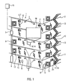
- Fig. 1 shows a perspective side view of a building 2 with partially illustrated interior view.
- an emergency lighting system 1 is arranged.
- This has a plurality of lights 3, which are arranged in rooms or corridors of the building 2.
- the lights include, for example, a number of security or escape sign lights 4. These have in part a pictogram for representing an escape route.
- the emergency light system 1 comprises a monitoring device 5 and a central, group or single battery system 6. This replaces in case of failure of an external power supply, the externally supplied AC voltage by a DC voltage.
- the monitoring device 5 within the building 2 is connected to a central or external monitoring device 16. This can be connected to the monitoring device 5 several buildings 2 or with multiple monitoring devices 5 in a building 2.
- Such an emergency lighting system is known from practice and meets the requirements according to predetermined standards such as IEC / EN 60598-2-22, EN 1838, ISO 3864, ISO 7010, ISO 30061 or EN 50172, IEC / EN 60364-5-56 and IEC / EN 60364-718.
- a number of transmitting stations 7 are arranged at least within the building as part of the emergency lighting system 1.
- An arrangement outside the building is also conceivable, especially in the area of escape routes with security and escape sign lights that lead to a collection point outside the building.
- Such transmitters 7 are, for example, the lights 3 or in particular in safety or escape sign lights 4 assigned. It is also possible that such transmitters 7 are arranged elsewhere and without direct assignment to a luminaire within the building 2.
- the various transmitters 7 form so-called beacons and form in particular Bluetooth low-energy beacons also called BLE beacons.
- the corresponding radio unit of such a transmitting station is relatively small and is supplied, for example, by a coin-cell battery or the like.
- the radio unit is essentially no larger than the button cell battery. It is also possible to supply directly from the emergency lighting system or from a luminaire.
- a corresponding transmitting station as a radio unit or BLE unit can be arranged on the outside of a corresponding lamp or even within this.
- the corresponding radio range of such a unit is usually 10 m or more and may be up to 50 m or more meters.
- the arrangement of the corresponding radio stations takes place in such a way that corresponding receivers are at any point within the building at least always in the reception area of a transmitting station.
- Such a receiving device 8 is in the lowest floor value Fig. 1 shown. This is a mobile receiver that is carried by a person within the building 2.
- An example of such a receiving device is a mobile device, such as a smartphone or the like, a tablet, a pager or the like.
- a smoke alarm device 9 for example, a smoke alarm device 9 or also different sensors 11.
- the receiving device 8 can communicate with the transmitting stations 7 within the building, it must have installed corresponding software in the form of, for example, an app.
- an app may be provided by the manufacturer on the receiving device 8.
- an app retrieval device 12 to the receiving device and then installed on this.
- the corresponding retrieval of the app can be done automatically or by manual input of the user of the receiving device.
- the corresponding app retrieval device can not only transmit the app to the receiving device, but can also make a registration of the receiving device. Such registration can in turn be automatic or by additional input of the user.
- a number of removal device 13 of the emergency lighting system 1 in Fig. 1 shown.
- Such a removal device 13 is to be opened by a person within the building 2 and contains a removable receiving device 8.
- This can be relatively simple to represent the corresponding, received from the respective transmitting station 7 data. This can be done graphically, acoustically, optically, or otherwise, for example by vibration of the receiving device.
- the representation on the receiver is used in this context, for.
- escape route display for example, if the existing security or escape sign lights 4 by fire, smoke or the like, are poor or not visible.
- the illustration may be for persons who have certain impairments, such as poor eyesight, blindness, deafness, walking difficulties or the like.
- the usual safety or escape sign lights 4 are generally arranged in an upper area of corresponding rooms or corridors of the building 2. As a result, they may be poor or invisible to persons with disabilities, and this also applies to non-impaired persons, for example if there is smoke in the corresponding rooms or corridors.
- the transmitting station 7 transmits information to the receiving device 8, which correspond, for example, to a floor plan of the corresponding floor, which represent a representation of an escape route, which represent an escape symbol, or correspond to an optical, acoustic or other sensory signal.
- this can supplement the escape route direction specified by the safety or escape route luminaires 4 or replace them if necessary, for example to specify a different escape route.
- a stationary receiving device 14 is shown in addition to the mobile receiving devices 8.
- This has the form of a computer with a screen, for example. On the screen, a corresponding representation of the information received from the transmitting station 7 takes place. In this case, a floor plan of the corresponding floor is enlarged.
- the corresponding senders are designed as Bluetooth low-energy communication units 15.
- This special type of communication has a sufficient range, is easy and inexpensive to install and is installed on almost any mobile receiving device, such as a smartphone or tablet.
- an optical communication in which, for example, as "visible light communication" the light output of LEDs is modulated to transmit information.
- a corresponding LED controller can be used.
- the optical communication needs, for example, the receiving device only a camera or the like.
- the optical communication does not disturb another radio standard and can be used instead of a Bluetooth low-energy communication or together with it. In both cases, unidirectional and / or bidirectional communication is always possible.
- FIG. 2 is a section of FIG. 1 shown, which shows a part of an interior of the building 2 as well as two receiving devices 8 in communication with corresponding transmitting points 7 inside the interior.
- the corresponding senders 7 are designed as BLE communication units 15, which are integrated, for example, in corresponding escape sign luminaires 4. Via a corresponding app on the receiving device 8, the connection to these BLE communication units 15 can be established. From these communication units corresponding information is then transmitted to the mobile receiving device 8.
- These show, for example, on a corresponding screen 18, a floor plan of the corresponding building part, in which the person with the mobile receiving device is straight.
- Other information may also be represented by the mobile receiving device 8, such as text signals, voice signals, acoustic or optical signals, vibrations, and the like. All of these different representations of the information received from the communication unit 15 serve to alert the appropriate person to a particular hazard situation or the like, either in addition to the safety or escape sign lights, or alternatively. For example. can be displayed on the screen 18 of the mobile receiving device a specific escape route, if, for example, the security and escape sign lights 4 are not clearly visible by smoke or fire.
- information can be transmitted via the mobile receiving device, in addition to these lights, which, for example, transmit additional information to physically impaired persons. This applies, for example, for persons with poor eyesight, hearing loss, physical disability or the like. That is, in this case, it is possible to address two or more senses of the corresponding person, and this can also be done in addition to already transmitted information through the safety or escape sign lights.
- the BLE communication unit is formed relatively small and usually powered by a corresponding battery, which may be, for example, a button cell battery.
- a corresponding battery which may be, for example, a button cell battery.
- the size of the communication unit is comparable to the size of the button cell or even lower.
- the communication unit can establish a connection to the receiver within a range of at least 10 m and up to 50 m or more meters. That is, it is usually sufficient if transmitters are, for example, spaced apart from each other in the building in accordance with their respective ranges.
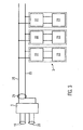
- FIG. 3 This has, for example, a monitoring device 5, which via corresponding lines and inputs with both a general power supply 19 and a safety power supply 20 in the form of, for example.
- a central or group battery system 6, s. FIG. 1 , connected is.
- the supply of the mains voltage of 220 V takes place via the general power supply 19. If this external and general mains voltage fails, the system switches over to the safety power supply 20. That means that the corresponding emergency lighting system is always ready for use and not dependent on an external power supply.
- the external power supply can be used to supply the corresponding safety power supply 20 with appropriate batteries or the like with sufficient charging voltage.
- a single battery system could also be used.
- the monitoring device 5 can be provided for an entire building or, depending on the size of the building, several of these monitoring devices 5 can be present. In addition, each of the monitoring devices 5 with a central or external monitoring device 16, s. FIG. 1 be connected.
- a voltage / data supply device 21 which supplies via corresponding connecting lines 25 a plurality of, for example, parallel connected lights and other facilities of the emergency lighting system.
- Such other facilities are, for example, in FIG. 1 shown, s. Smoke detector device 9, fire alarm device 10, sensors 11, app retrieval device 12 and the like.
- FIG. 3 a series of lights 3 are shown, which in the illustrated embodiment, depending on the lamp used, for example.
- Reference numeral 23. These serve for the corresponding supply of the light source, such as LED, fluorescent tube, or the like.
- each of the lights 3 may have a light monitoring device 22.
- This is also used, for example, to integrate a corresponding BLE communication unit 15, s. again FIG. 1 , which may be arranged in the luminaire 3 or at least this is assigned.
- a corresponding communication unit is arranged or assigned to this luminaire.
- the various communication units in the form of a master-slave arrangement enable hierarchical management of the communication.
- one of the transmitting stations or communication units acts as a master, while neighboring transmitters / communication units are slaves. That is, the master can communicate with each slave to, for example, relay information or track a receiving device using the slaves within the building.
- the master can also initiate positioning of the receiving device via its slaves, for example via triangulation or the like.
- the master can also monitor and control the data transmission of the slaves with regard to the corresponding receiving devices.
- each receiving device not only the possibility of communication with a transmitting station or communication unit 7, 15 is given, but also a receiving device 8 as sending station 7 with a corresponding BLE communication unit 15 is provided. That is, in this case, a receiving device 8 could transmit to other receiving devices, the corresponding information that receives this specific receiving device, for example. From a transmitting station 7 within the building. As a result, a sufficient coverage could be achieved by corresponding receivers 8 over the entire building even with a smaller number of transmitters 7 within the building. This also applies to stationary receivers, which may be located within the building, s. 14 in FIG. 1 , This can also be used as a further transmitting station.
- corresponding transmitting stations can not only be arranged, for example, in security or escape sign luminaires or assigned to them.
- Corresponding transmitting stations can also be arranged independently of other facilities of the emergency lighting system within the building and, for example, be integrated into switches, sockets or the like due to their small size.
- Corresponding stations are simple and relatively inexpensive, so that they can be arranged in large numbers within a building. They increase the effectiveness of the emergency lighting system by, for example, in addition to information that can already be transmitted by security or escape sign lights, more information in particular with regard to two, three, or more meaning information can be transmitted.
- the corresponding stations in case of failure or inapplicability of escape sign lights or the like can replace them by, for example, allow a Wegtechnisch.
- corresponding information is transmitted to receiving devices. On this then this information is displayed graphically or otherwise or reproduced by them also visually, acoustically or by vibration.
Landscapes
- Physics & Mathematics (AREA)
- General Physics & Mathematics (AREA)
- Alarm Systems (AREA)
- Audible And Visible Signals (AREA)
Applications Claiming Priority (1)
| Application Number | Priority Date | Filing Date | Title |
|---|---|---|---|
| DE102014004170.0A DE102014004170A1 (de) | 2014-03-21 | 2014-03-21 | Notlichtsystem und entsprechendes Verfahren |
Publications (3)
| Publication Number | Publication Date |
|---|---|
| EP2922039A2 true EP2922039A2 (fr) | 2015-09-23 |
| EP2922039A3 EP2922039A3 (fr) | 2015-10-07 |
| EP2922039B1 EP2922039B1 (fr) | 2021-02-24 |
Family
ID=52686048
Family Applications (1)
| Application Number | Title | Priority Date | Filing Date |
|---|---|---|---|
| EP15000735.9A Revoked EP2922039B1 (fr) | 2014-03-21 | 2015-03-12 | Système lumineux de secours et procédé correspondant |
Country Status (2)
| Country | Link |
|---|---|
| EP (1) | EP2922039B1 (fr) |
| DE (1) | DE102014004170A1 (fr) |
Cited By (6)
| Publication number | Priority date | Publication date | Assignee | Title |
|---|---|---|---|---|
| CN107666756A (zh) * | 2017-10-20 | 2018-02-06 | 北京易络特科技有限公司 | 无线集中式应急照明控制系统 |
| CN109660974A (zh) * | 2019-01-25 | 2019-04-19 | 华能西藏雅鲁藏布江水电开发投资有限公司 | 用于水电站的智能逃生疏散系统 |
| EP2922039B1 (fr) | 2014-03-21 | 2021-02-24 | Eaton Safety IP GmbH & Co. KG | Système lumineux de secours et procédé correspondant |
| CN114556453A (zh) * | 2019-11-14 | 2022-05-27 | 宗拓贝尔照明器材有限公司 | 动态和/或自适应路径指引系统 |
| EP3502731B1 (fr) | 2017-12-20 | 2023-08-02 | INOTEC Sicherheitstechnik GmbH | Dispositif de détection des personnes et d'identification d'un trajet dans un bâtiment |
| CN121462081A (zh) * | 2026-01-05 | 2026-02-03 | 深圳星网信通科技股份有限公司 | 基于可见光通信的安防信息发布方法、设备和存储介质 |
Families Citing this family (1)
| Publication number | Priority date | Publication date | Assignee | Title |
|---|---|---|---|---|
| DE102015215649A1 (de) * | 2015-08-17 | 2017-02-23 | Siemens Aktiengesellschaft | Verfahren und Vorrichtung |
Citations (3)
| Publication number | Priority date | Publication date | Assignee | Title |
|---|---|---|---|---|
| EP1361206A1 (fr) | 1995-07-18 | 2003-11-12 | Asahi Kasei Kabushiki Kaisha | Procédé pour la préparation d'esters carboxyliques |
| US7605695B2 (en) | 2006-11-14 | 2009-10-20 | Harris Corporation | Automatic discovery and classification of detectors used in unattended ground sensor systems |
| US20130218931A1 (en) | 2007-04-04 | 2013-08-22 | Pathfinders International, Llc | Virtual badge, device and method |
Family Cites Families (22)
| Publication number | Priority date | Publication date | Assignee | Title |
|---|---|---|---|---|
| WO2004038962A1 (fr) | 2002-10-24 | 2004-05-06 | Nakagawa Laboratories, Inc. | Dispositif de communication pour systeme de diffusion |
| KR20060081555A (ko) | 2005-01-10 | 2006-07-13 | 엘지전자 주식회사 | 비상구 안내 시스템과 비상구 안내 출력 시스템 및 그를이용한 비상구 안내 방법 |
| JP4634207B2 (ja) | 2005-04-12 | 2011-02-16 | 富士通株式会社 | 防災情報管理システム |
| US8836580B2 (en) * | 2005-05-09 | 2014-09-16 | Ehud Mendelson | RF proximity tags providing indoor and outdoor navigation and method of use |
| US7605696B2 (en) | 2005-12-21 | 2009-10-20 | Cary Quatro | System and method for real time location tracking and communications |
| DE102006014012A1 (de) | 2006-03-27 | 2007-10-11 | Ethan Ho | Sicherheitseinrichtung zum Abgrenzen einer Notfallzone |
| US8491159B2 (en) | 2006-03-28 | 2013-07-23 | Wireless Environment, Llc | Wireless emergency lighting system |
| JP2008225630A (ja) | 2007-03-09 | 2008-09-25 | Nec Corp | 避難者誘導システム、避難者誘導方法及び避難者誘導プログラム |
| JP2009238135A (ja) | 2008-03-28 | 2009-10-15 | Kyocera Corp | 無線電子機器 |
| CN101556158A (zh) | 2008-04-11 | 2009-10-14 | 英华达(上海)科技有限公司 | 导航方法及其手持导航装置和导航系统 |
| KR101174542B1 (ko) | 2009-09-22 | 2012-08-16 | 한양대학교 산학협력단 | 이동 단말, 이동 단말의 위치 측정 시스템 및 그 방법 |
| CN102688566B (zh) | 2011-03-24 | 2014-06-18 | 鸿富锦精密工业(深圳)有限公司 | 火灾指引逃生系统及其逃生指引方法 |
| US20130116922A1 (en) | 2011-11-08 | 2013-05-09 | Hon Hai Precision Industry Co., Ltd. | Emergency guiding system, server and portable device using augmented reality |
| US8547036B2 (en) * | 2011-11-20 | 2013-10-01 | Available For Licensing | Solid state light system with broadband optical communication capability |
| DE102012201180A1 (de) | 2012-01-27 | 2013-08-01 | Zumtobel Lighting Gmbh | System und Verfahren zur Anzeige einer fluchtwegrelevanten Information |
| JP2013164695A (ja) | 2012-02-09 | 2013-08-22 | Osamu Mogi | 避難誘導システム |
| KR101324849B1 (ko) | 2012-02-17 | 2013-11-01 | 이진석 | 휴대 단말기를 이용한 인명구조 시스템 및 방법 |
| DE202012104642U1 (de) | 2012-03-28 | 2013-01-16 | Insta Elektro Gmbh | Vorrichtung zur Personenüberwachung in einem Gebäude sowie Gebäudeinstallationssystem |
| CN102970413B (zh) | 2012-10-26 | 2014-11-12 | 广东欧珀移动通信有限公司 | 一种智能手机运行方法 |
| DE102013200815A1 (de) | 2013-01-18 | 2014-07-24 | Siemens Aktiengesellschaft | Dynamische Fluchtwegkennzeichnung |
| DE102013201873B4 (de) | 2013-02-05 | 2017-09-21 | Siemens Schweiz Ag | Dynamische Notfallhilfe |
| DE102014004170A1 (de) | 2014-03-21 | 2015-09-24 | Ceag Notlichtsysteme Gmbh | Notlichtsystem und entsprechendes Verfahren |
-
2014
- 2014-03-21 DE DE102014004170.0A patent/DE102014004170A1/de not_active Withdrawn
-
2015
- 2015-03-12 EP EP15000735.9A patent/EP2922039B1/fr not_active Revoked
Patent Citations (3)
| Publication number | Priority date | Publication date | Assignee | Title |
|---|---|---|---|---|
| EP1361206A1 (fr) | 1995-07-18 | 2003-11-12 | Asahi Kasei Kabushiki Kaisha | Procédé pour la préparation d'esters carboxyliques |
| US7605695B2 (en) | 2006-11-14 | 2009-10-20 | Harris Corporation | Automatic discovery and classification of detectors used in unattended ground sensor systems |
| US20130218931A1 (en) | 2007-04-04 | 2013-08-22 | Pathfinders International, Llc | Virtual badge, device and method |
Cited By (7)
| Publication number | Priority date | Publication date | Assignee | Title |
|---|---|---|---|---|
| EP2922039B1 (fr) | 2014-03-21 | 2021-02-24 | Eaton Safety IP GmbH & Co. KG | Système lumineux de secours et procédé correspondant |
| CN107666756A (zh) * | 2017-10-20 | 2018-02-06 | 北京易络特科技有限公司 | 无线集中式应急照明控制系统 |
| EP3502731B1 (fr) | 2017-12-20 | 2023-08-02 | INOTEC Sicherheitstechnik GmbH | Dispositif de détection des personnes et d'identification d'un trajet dans un bâtiment |
| EP3502731B2 (fr) † | 2017-12-20 | 2026-03-11 | INOTEC Sicherheitstechnik GmbH | Dispositif de détection des personnes et d'identification d'un trajet dans un bâtiment |
| CN109660974A (zh) * | 2019-01-25 | 2019-04-19 | 华能西藏雅鲁藏布江水电开发投资有限公司 | 用于水电站的智能逃生疏散系统 |
| CN114556453A (zh) * | 2019-11-14 | 2022-05-27 | 宗拓贝尔照明器材有限公司 | 动态和/或自适应路径指引系统 |
| CN121462081A (zh) * | 2026-01-05 | 2026-02-03 | 深圳星网信通科技股份有限公司 | 基于可见光通信的安防信息发布方法、设备和存储介质 |
Also Published As
| Publication number | Publication date |
|---|---|
| EP2922039A3 (fr) | 2015-10-07 |
| EP2922039B1 (fr) | 2021-02-24 |
| DE102014004170A1 (de) | 2015-09-24 |
Similar Documents
| Publication | Publication Date | Title |
|---|---|---|
| EP2922039B1 (fr) | Système lumineux de secours et procédé correspondant | |
| WO2006086812A2 (fr) | Systeme d'evacuation equipe de dispositifs lumineux de reperage | |
| EP2936467A1 (fr) | Surveillance d'une zone de dangers | |
| DE4241862C2 (de) | Sicherheitssystem sowie Verfahren, mit dem das Sicherheitssystem betrieben wird | |
| EP3937158A1 (fr) | Dispositif d'affichage de chemins d'évacuation intelligent pour une installation d'évacuation optique et acoustique, ainsi que système de guidage | |
| EP3247166A1 (fr) | Procédé et dispositif destinés à délivrer des messages d'avertissement | |
| DE102005021736B4 (de) | Einrichtung zur Steuerung von Rettungsmaßnahmen | |
| DE102015211149B4 (de) | Intelligente Zusatzmodule für Leuchten | |
| WO2022043371A1 (fr) | Système d'ascenseur ayant des dispositifs de commande d'ascenseur pour passagers à mobilité limitée | |
| DE102021106154A1 (de) | Wohnanlagen- und gebäudeinfrastruktursteuerung für notfalleinsätze | |
| DE102005014345A1 (de) | Signalvorrichtung, insbesondere Signalsäule | |
| EP4270347B1 (fr) | Système de sécurité | |
| DE102016124700A1 (de) | Alarmeinheit und Alarmsystem | |
| EP3557548A1 (fr) | Module combiné destiné au montage mural ou au plafond | |
| EP3453191A1 (fr) | Système radio d'appel de détresse | |
| EP2660790A1 (fr) | Système de lumière de secours et dispositif de lumière de secours ainsi que procédé de détermination d'un signal d'appel d'urgence de position précise | |
| DE102017218944A1 (de) | Vorrichtung und Verfahren zur Ausgabe einer Information über den Betriebsstatus von einer in einem Fahrzeug angeordneten Batterie | |
| DE102018006831A1 (de) | Vorrichtung und Verfahren zur Ermittlung und Anzeige von Gefahrenzuständen | |
| DE102016104486A1 (de) | Beleuchtungssystem mit Signalisierung einer Kommunikationsverbindung | |
| WO2018086780A1 (fr) | Système d'éclairage avec évaluation de signal d'analyse | |
| DE102023207855A1 (de) | Verfahren zum Betreiben eines elektronischen Geräts, elektronisches Gerät, Mobilfunkgerät und Server | |
| DE102006014012A1 (de) | Sicherheitseinrichtung zum Abgrenzen einer Notfallzone | |
| DE102020002182A1 (de) | Mobile Warnvorrichtung mit Steuerungs-, Übertragungs- und Anzeigenvorrichtung | |
| WO2021043900A1 (fr) | Dispositif d'exploitation, ensemble réseau équipé de ce dispositif d'exploitation et procédé de sécurisation d'une liaison radio pour ce dispositif d'exploitation | |
| DE10238891A1 (de) | Verfahren zur Leitung von Einsatzkräften zu einem Einsatzort in einem Gebäude und Gebäudemanagementsystem |
Legal Events
| Date | Code | Title | Description |
|---|---|---|---|
| PUAL | Search report despatched |
Free format text: ORIGINAL CODE: 0009013 |
|
| PUAI | Public reference made under article 153(3) epc to a published international application that has entered the european phase |
Free format text: ORIGINAL CODE: 0009012 |
|
| AK | Designated contracting states |
Kind code of ref document: A2 Designated state(s): AL AT BE BG CH CY CZ DE DK EE ES FI FR GB GR HR HU IE IS IT LI LT LU LV MC MK MT NL NO PL PT RO RS SE SI SK SM TR |
|
| AX | Request for extension of the european patent |
Extension state: BA ME |
|
| RIC1 | Information provided on ipc code assigned before grant |
Ipc: G08B 7/06 20060101AFI20150827BHEP |
|
| AK | Designated contracting states |
Kind code of ref document: A3 Designated state(s): AL AT BE BG CH CY CZ DE DK EE ES FI FR GB GR HR HU IE IS IT LI LT LU LV MC MK MT NL NO PL PT RO RS SE SI SK SM TR |
|
| AX | Request for extension of the european patent |
Extension state: BA ME |
|
| 17P | Request for examination filed |
Effective date: 20151208 |
|
| RBV | Designated contracting states (corrected) |
Designated state(s): AL AT BE BG CH CY CZ DE DK EE ES FI FR GB GR HR HU IE IS IT LI LT LU LV MC MK MT NL NO PL PT RO RS SE SI SK SM TR |
|
| RAP1 | Party data changed (applicant data changed or rights of an application transferred) |
Owner name: EATON SAFETY IP GMBH & CO. KG |
|
| STAA | Information on the status of an ep patent application or granted ep patent |
Free format text: STATUS: EXAMINATION IS IN PROGRESS |
|
| 17Q | First examination report despatched |
Effective date: 20171128 |
|
| TPAC | Observations filed by third parties |
Free format text: ORIGINAL CODE: EPIDOSNTIPA |
|
| GRAP | Despatch of communication of intention to grant a patent |
Free format text: ORIGINAL CODE: EPIDOSNIGR1 |
|
| STAA | Information on the status of an ep patent application or granted ep patent |
Free format text: STATUS: GRANT OF PATENT IS INTENDED |
|
| INTG | Intention to grant announced |
Effective date: 20200904 |
|
| GRAS | Grant fee paid |
Free format text: ORIGINAL CODE: EPIDOSNIGR3 |
|
| GRAA | (expected) grant |
Free format text: ORIGINAL CODE: 0009210 |
|
| STAA | Information on the status of an ep patent application or granted ep patent |
Free format text: STATUS: THE PATENT HAS BEEN GRANTED |
|
| AK | Designated contracting states |
Kind code of ref document: B1 Designated state(s): AL AT BE BG CH CY CZ DE DK EE ES FI FR GB GR HR HU IE IS IT LI LT LU LV MC MK MT NL NO PL PT RO RS SE SI SK SM TR |
|
| REG | Reference to a national code |
Ref country code: GB Ref legal event code: FG4D Free format text: NOT ENGLISH |
|
| REG | Reference to a national code |
Ref country code: CH Ref legal event code: EP |
|
| REG | Reference to a national code |
Ref country code: AT Ref legal event code: REF Ref document number: 1365468 Country of ref document: AT Kind code of ref document: T Effective date: 20210315 |
|
| REG | Reference to a national code |
Ref country code: IE Ref legal event code: FG4D Free format text: LANGUAGE OF EP DOCUMENT: GERMAN |
|
| REG | Reference to a national code |
Ref country code: DE Ref legal event code: R096 Ref document number: 502015014273 Country of ref document: DE |
|
| REG | Reference to a national code |
Ref country code: FI Ref legal event code: FGE |
|
| REG | Reference to a national code |
Ref country code: NL Ref legal event code: FP |
|
| REG | Reference to a national code |
Ref country code: SE Ref legal event code: TRGR |
|
| REG | Reference to a national code |
Ref country code: NO Ref legal event code: T2 Effective date: 20210224 Ref country code: LT Ref legal event code: MG9D |
|
| PG25 | Lapsed in a contracting state [announced via postgrant information from national office to epo] |
Ref country code: LT Free format text: LAPSE BECAUSE OF FAILURE TO SUBMIT A TRANSLATION OF THE DESCRIPTION OR TO PAY THE FEE WITHIN THE PRESCRIBED TIME-LIMIT Effective date: 20210224 Ref country code: PT Free format text: LAPSE BECAUSE OF FAILURE TO SUBMIT A TRANSLATION OF THE DESCRIPTION OR TO PAY THE FEE WITHIN THE PRESCRIBED TIME-LIMIT Effective date: 20210624 Ref country code: GR Free format text: LAPSE BECAUSE OF FAILURE TO SUBMIT A TRANSLATION OF THE DESCRIPTION OR TO PAY THE FEE WITHIN THE PRESCRIBED TIME-LIMIT Effective date: 20210525 Ref country code: HR Free format text: LAPSE BECAUSE OF FAILURE TO SUBMIT A TRANSLATION OF THE DESCRIPTION OR TO PAY THE FEE WITHIN THE PRESCRIBED TIME-LIMIT Effective date: 20210224 Ref country code: BG Free format text: LAPSE BECAUSE OF FAILURE TO SUBMIT A TRANSLATION OF THE DESCRIPTION OR TO PAY THE FEE WITHIN THE PRESCRIBED TIME-LIMIT Effective date: 20210524 |
|
| PG25 | Lapsed in a contracting state [announced via postgrant information from national office to epo] |
Ref country code: PL Free format text: LAPSE BECAUSE OF FAILURE TO SUBMIT A TRANSLATION OF THE DESCRIPTION OR TO PAY THE FEE WITHIN THE PRESCRIBED TIME-LIMIT Effective date: 20210224 Ref country code: LV Free format text: LAPSE BECAUSE OF FAILURE TO SUBMIT A TRANSLATION OF THE DESCRIPTION OR TO PAY THE FEE WITHIN THE PRESCRIBED TIME-LIMIT Effective date: 20210224 Ref country code: RS Free format text: LAPSE BECAUSE OF FAILURE TO SUBMIT A TRANSLATION OF THE DESCRIPTION OR TO PAY THE FEE WITHIN THE PRESCRIBED TIME-LIMIT Effective date: 20210224 |
|
| PG25 | Lapsed in a contracting state [announced via postgrant information from national office to epo] |
Ref country code: IS Free format text: LAPSE BECAUSE OF FAILURE TO SUBMIT A TRANSLATION OF THE DESCRIPTION OR TO PAY THE FEE WITHIN THE PRESCRIBED TIME-LIMIT Effective date: 20210624 |
|
| PG25 | Lapsed in a contracting state [announced via postgrant information from national office to epo] |
Ref country code: EE Free format text: LAPSE BECAUSE OF FAILURE TO SUBMIT A TRANSLATION OF THE DESCRIPTION OR TO PAY THE FEE WITHIN THE PRESCRIBED TIME-LIMIT Effective date: 20210224 Ref country code: CZ Free format text: LAPSE BECAUSE OF FAILURE TO SUBMIT A TRANSLATION OF THE DESCRIPTION OR TO PAY THE FEE WITHIN THE PRESCRIBED TIME-LIMIT Effective date: 20210224 Ref country code: SM Free format text: LAPSE BECAUSE OF FAILURE TO SUBMIT A TRANSLATION OF THE DESCRIPTION OR TO PAY THE FEE WITHIN THE PRESCRIBED TIME-LIMIT Effective date: 20210224 |
|
| REG | Reference to a national code |
Ref country code: CH Ref legal event code: PL |
|
| REG | Reference to a national code |
Ref country code: DE Ref legal event code: R026 Ref document number: 502015014273 Country of ref document: DE |
|
| PLBI | Opposition filed |
Free format text: ORIGINAL CODE: 0009260 |
|
| PG25 | Lapsed in a contracting state [announced via postgrant information from national office to epo] |
Ref country code: SK Free format text: LAPSE BECAUSE OF FAILURE TO SUBMIT A TRANSLATION OF THE DESCRIPTION OR TO PAY THE FEE WITHIN THE PRESCRIBED TIME-LIMIT Effective date: 20210224 Ref country code: RO Free format text: LAPSE BECAUSE OF FAILURE TO SUBMIT A TRANSLATION OF THE DESCRIPTION OR TO PAY THE FEE WITHIN THE PRESCRIBED TIME-LIMIT Effective date: 20210224 Ref country code: MC Free format text: LAPSE BECAUSE OF FAILURE TO SUBMIT A TRANSLATION OF THE DESCRIPTION OR TO PAY THE FEE WITHIN THE PRESCRIBED TIME-LIMIT Effective date: 20210224 Ref country code: ES Free format text: LAPSE BECAUSE OF FAILURE TO SUBMIT A TRANSLATION OF THE DESCRIPTION OR TO PAY THE FEE WITHIN THE PRESCRIBED TIME-LIMIT Effective date: 20210224 Ref country code: DK Free format text: LAPSE BECAUSE OF FAILURE TO SUBMIT A TRANSLATION OF THE DESCRIPTION OR TO PAY THE FEE WITHIN THE PRESCRIBED TIME-LIMIT Effective date: 20210224 |
|
| PLAX | Notice of opposition and request to file observation + time limit sent |
Free format text: ORIGINAL CODE: EPIDOSNOBS2 |
|
| REG | Reference to a national code |
Ref country code: BE Ref legal event code: MM Effective date: 20210331 |
|
| REG | Reference to a national code |
Ref country code: FI Ref legal event code: MDE Opponent name: RP-TECHNIK GMBH |
|
| 26 | Opposition filed |
Opponent name: RP-TECHNIK GMBH Effective date: 20211123 |
|
| PG25 | Lapsed in a contracting state [announced via postgrant information from national office to epo] |
Ref country code: CH Free format text: LAPSE BECAUSE OF NON-PAYMENT OF DUE FEES Effective date: 20210331 Ref country code: AL Free format text: LAPSE BECAUSE OF FAILURE TO SUBMIT A TRANSLATION OF THE DESCRIPTION OR TO PAY THE FEE WITHIN THE PRESCRIBED TIME-LIMIT Effective date: 20210224 Ref country code: LI Free format text: LAPSE BECAUSE OF NON-PAYMENT OF DUE FEES Effective date: 20210331 Ref country code: LU Free format text: LAPSE BECAUSE OF NON-PAYMENT OF DUE FEES Effective date: 20210312 Ref country code: IE Free format text: LAPSE BECAUSE OF NON-PAYMENT OF DUE FEES Effective date: 20210312 |
|
| PG25 | Lapsed in a contracting state [announced via postgrant information from national office to epo] |
Ref country code: SI Free format text: LAPSE BECAUSE OF FAILURE TO SUBMIT A TRANSLATION OF THE DESCRIPTION OR TO PAY THE FEE WITHIN THE PRESCRIBED TIME-LIMIT Effective date: 20210224 |
|
| PLBB | Reply of patent proprietor to notice(s) of opposition received |
Free format text: ORIGINAL CODE: EPIDOSNOBS3 |
|
| PG25 | Lapsed in a contracting state [announced via postgrant information from national office to epo] |
Ref country code: IT Free format text: LAPSE BECAUSE OF FAILURE TO SUBMIT A TRANSLATION OF THE DESCRIPTION OR TO PAY THE FEE WITHIN THE PRESCRIBED TIME-LIMIT Effective date: 20210224 |
|
| REG | Reference to a national code |
Ref country code: AT Ref legal event code: MM01 Ref document number: 1365468 Country of ref document: AT Kind code of ref document: T Effective date: 20210312 |
|
| PG25 | Lapsed in a contracting state [announced via postgrant information from national office to epo] |
Ref country code: IS Free format text: LAPSE BECAUSE OF FAILURE TO SUBMIT A TRANSLATION OF THE DESCRIPTION OR TO PAY THE FEE WITHIN THE PRESCRIBED TIME-LIMIT Effective date: 20210624 |
|
| RAP2 | Party data changed (patent owner data changed or rights of a patent transferred) |
Owner name: EATON INTELLIGENT POWER LIMITED |
|
| REG | Reference to a national code |
Ref country code: DE Ref legal event code: R081 Ref document number: 502015014273 Country of ref document: DE Owner name: EATON INTELLIGENT POWER LIMITED, IE Free format text: FORMER OWNER: EATON SAFETY IP GMBH & CO. KG, 12529 SCHOENEFELD, DE |
|
| REG | Reference to a national code |
Ref country code: NL Ref legal event code: PD Owner name: EATON INTELLIGENT POWER LIMITED; IE Free format text: DETAILS ASSIGNMENT: CHANGE OF OWNER(S), ASSIGNMENT; FORMER OWNER NAME: EATON SAFETY IP GMBH & CO. KG Effective date: 20220704 |
|
| PG25 | Lapsed in a contracting state [announced via postgrant information from national office to epo] |
Ref country code: BE Free format text: LAPSE BECAUSE OF NON-PAYMENT OF DUE FEES Effective date: 20210331 |
|
| PLAY | Examination report in opposition despatched + time limit |
Free format text: ORIGINAL CODE: EPIDOSNORE2 |
|
| PG25 | Lapsed in a contracting state [announced via postgrant information from national office to epo] |
Ref country code: AT Free format text: LAPSE BECAUSE OF NON-PAYMENT OF DUE FEES Effective date: 20210312 |
|
| REG | Reference to a national code |
Ref country code: NO Ref legal event code: CREP Representative=s name: BRYN AARFLOT AS, STORTINGSGATA 8, 0161 OSLO, NORGE |
|
| PLBC | Reply to examination report in opposition received |
Free format text: ORIGINAL CODE: EPIDOSNORE3 |
|
| REG | Reference to a national code |
Ref country code: GB Ref legal event code: 732E Free format text: REGISTERED BETWEEN 20221103 AND 20221109 |
|
| PGFP | Annual fee paid to national office [announced via postgrant information from national office to epo] |
Ref country code: NL Payment date: 20230221 Year of fee payment: 9 |
|
| PGFP | Annual fee paid to national office [announced via postgrant information from national office to epo] |
Ref country code: NO Payment date: 20230223 Year of fee payment: 9 Ref country code: FR Payment date: 20230222 Year of fee payment: 9 Ref country code: FI Payment date: 20230223 Year of fee payment: 9 |
|
| PG25 | Lapsed in a contracting state [announced via postgrant information from national office to epo] |
Ref country code: HU Free format text: LAPSE BECAUSE OF FAILURE TO SUBMIT A TRANSLATION OF THE DESCRIPTION OR TO PAY THE FEE WITHIN THE PRESCRIBED TIME-LIMIT; INVALID AB INITIO Effective date: 20150312 |
|
| PGFP | Annual fee paid to national office [announced via postgrant information from national office to epo] |
Ref country code: SE Payment date: 20230222 Year of fee payment: 9 Ref country code: GB Payment date: 20230222 Year of fee payment: 9 Ref country code: DE Payment date: 20230221 Year of fee payment: 9 |
|
| P01 | Opt-out of the competence of the unified patent court (upc) registered |
Effective date: 20230521 |
|
| PG25 | Lapsed in a contracting state [announced via postgrant information from national office to epo] |
Ref country code: CY Free format text: LAPSE BECAUSE OF FAILURE TO SUBMIT A TRANSLATION OF THE DESCRIPTION OR TO PAY THE FEE WITHIN THE PRESCRIBED TIME-LIMIT Effective date: 20210224 |
|
| PG25 | Lapsed in a contracting state [announced via postgrant information from national office to epo] |
Ref country code: MK Free format text: LAPSE BECAUSE OF FAILURE TO SUBMIT A TRANSLATION OF THE DESCRIPTION OR TO PAY THE FEE WITHIN THE PRESCRIBED TIME-LIMIT Effective date: 20210224 |
|
| RDAF | Communication despatched that patent is revoked |
Free format text: ORIGINAL CODE: EPIDOSNREV1 |
|
| REG | Reference to a national code |
Ref country code: DE Ref legal event code: R103 Ref document number: 502015014273 Country of ref document: DE Ref country code: DE Ref legal event code: R064 Ref document number: 502015014273 Country of ref document: DE |
|
| RDAG | Patent revoked |
Free format text: ORIGINAL CODE: 0009271 |
|
| STAA | Information on the status of an ep patent application or granted ep patent |
Free format text: STATUS: PATENT REVOKED |
|
| PG25 | Lapsed in a contracting state [announced via postgrant information from national office to epo] |
Ref country code: MT Free format text: LAPSE BECAUSE OF FAILURE TO SUBMIT A TRANSLATION OF THE DESCRIPTION OR TO PAY THE FEE WITHIN THE PRESCRIBED TIME-LIMIT Effective date: 20210224 |
|
| REG | Reference to a national code |
Ref country code: CH Ref legal event code: PL |
|
| PG25 | Lapsed in a contracting state [announced via postgrant information from national office to epo] |
Ref country code: FI Free format text: LAPSE BECAUSE OF NON-PAYMENT OF DUE FEES Effective date: 20240312 |
|
| 27W | Patent revoked |
Effective date: 20240613 |
|
| GBPR | Gb: patent revoked under art. 102 of the ep convention designating the uk as contracting state |
Effective date: 20240613 |
|
| PG25 | Lapsed in a contracting state [announced via postgrant information from national office to epo] |
Ref country code: FI Free format text: LAPSE BECAUSE OF NON-PAYMENT OF DUE FEES Effective date: 20240312 |
|
| REG | Reference to a national code |
Ref country code: AT Ref legal event code: MA03 Ref document number: 1365468 Country of ref document: AT Kind code of ref document: T Effective date: 20240613 |
|
| PG25 | Lapsed in a contracting state [announced via postgrant information from national office to epo] |
Ref country code: NO Free format text: LAPSE BECAUSE OF NON-PAYMENT OF DUE FEES Effective date: 20240331 |
|
| PG25 | Lapsed in a contracting state [announced via postgrant information from national office to epo] |
Ref country code: NO Free format text: LAPSE BECAUSE OF NON-PAYMENT OF DUE FEES Effective date: 20240331 |
|
| REG | Reference to a national code |
Ref country code: SE Ref legal event code: ECNC |
|
| PG25 | Lapsed in a contracting state [announced via postgrant information from national office to epo] |
Ref country code: FR Free format text: LAPSE BECAUSE OF NON-PAYMENT OF DUE FEES Effective date: 20240312 |
|
| PG25 | Lapsed in a contracting state [announced via postgrant information from national office to epo] |
Ref country code: NL Free format text: THE PATENT HAS BEEN ANNULLED BY A DECISION OF A NATIONAL AUTHORITY Effective date: 20240613 |
|
| PG25 | Lapsed in a contracting state [announced via postgrant information from national office to epo] |
Ref country code: GB Free format text: LAPSE BECAUSE OF NON-PAYMENT OF DUE FEES Effective date: 20241203 |
|
| PG25 | Lapsed in a contracting state [announced via postgrant information from national office to epo] |
Ref country code: TR Free format text: LAPSE BECAUSE OF FAILURE TO SUBMIT A TRANSLATION OF THE DESCRIPTION OR TO PAY THE FEE WITHIN THE PRESCRIBED TIME-LIMIT Effective date: 20210224 |
|
| PG25 | Lapsed in a contracting state [announced via postgrant information from national office to epo] |
Ref country code: SE Free format text: LAPSE BECAUSE OF NON-PAYMENT OF DUE FEES Effective date: 20240313 |